© 2002 SafeCode Inc. All rights reserved.
A SafeCode Inc. Publication
INSTALLING AIR CONDITIONING IN 64.5—
66 CLASSIC MUSTANGS
THIRD EDITON
WWW.MUSTANG PROJECT.COM
With this Manual
you will:
•
Save hours in installation time
•
Order a system properly
•
Prepare your mustang for AC
•
Install all components
•
Test and maintain
•Enjoy the cool!
Fig. 2 Ford Pump Fig. 1 Eaton Pump
All of the equipment pro-vided in this manual was purchased from Classic Auto Air Manufacturing Company, 2020 W. Ken-nedy Blvd., Tampa, Flor-ida 33606
Phone: 813-251-4994,813-251-2356
Inside you will find detailed instructions on how to in-stall air conditioning in your classic 1965 or 1966 mustang. These instruc-tions were formulated through an actual installa-tion in an early 1965 Mus-tang fastback.
We will provide step-by-step instructions diagram and over 100 photos! Less than 10 % of all early Mustangs were originally equipped with factory air. Therefore almost all of the
cars you see today with air were converted at some time in the car’s life. In many cases those conver-sions were improperly done.
Using a system provided by Classic Auto Air of Tampa Florida we will provide instructions on how to do a correct installation that looks just like the original did in 65/66!
The approach for this instlation was to make an al-most show correct
installa-tion yet provide a high level of cooling perform-ance and drivability. We will identify and steer you around all of the pitfalls of the AC installation so that you can get your system installed and running in the shortest possible time. This manual will literally save you hours of work and provide you with the best chance of a working instal-lation the first time!
What’s inside this Manual
3. Do you want a more efficient Saden com-pressor or and original rebuilt compressor? 4. What size radiator do
you have — 2,3 or 4 row?
5. Which refrigerant will you be using? Choices are R134A and R12. 6. Do you want an
origi-nal restored under dash evaporator or a lower cost non original unit?
7. What is the build date
of your car?
Now we will examine each item in detail.
Figures 1and 2. Early Mus-tangs came with two power steering pumps known as Eaton and Ford.
The “Ford” pumps inte-grated the fluid reservoir and the pump into one as-sembly see the figures be-low. While the Eaton pumps had a separate fluid reservoir which rested on top of a die cast pump unit. Be sure and specify which
Ordering your AC system
Though you can assembly all of the parts required for an AC system yourself for the purposes of this installa-tion manual we will be as-suming you will be order-ing a complete system from Classic Auto Air (CAA). Before you make that call to CAA you should have sev-eral pieces of information at hand.
1. Does your car have power steering? 2. If yes to 1 is it Eaton or Ford?
“Less than
10% of all
early Mustangs
were
originally
equipped with
factory air.”
Fig. 6 CAAs “Daily Driver” Fig. 4 High Efficiency Sanden Compressor
Fig. 3 Original Ford Compressor
Fig. 8 1965 Mustang Chrome and brushed Aluminum Evaporator
Fig. 7 1965 Evaporator Pictured here are
the original 65/66 units and the CAA aftermarket re-placement called “Daily Driver”. The 66 Evapora-tor was just a bit smaller than the 65 unit and fea-tured a camera case finish with chrome trim.
Parts from these evapora-tors are not interchange-able.
In addition the 66 evapora-tor was a satin finish alumi-num and chrome. Both evaporators work in the same way with a control for fan speed and another for temperature regulation. Below in Figure 8 you will see the 65 evaporator we will install in our example.
It has been expertly reconditioned by CAA including new chrome and a very nicely finished ford logo. On top of the evaporator rests the so called “coin tray”. Finally its very helpful to know the exact manufacturing date of your car. To determine this simply use a VIN calculator. Many of these are available on the internet for example:
http://
www.classicponycars.com/ data.html
if any you have as this ef-fects the type of compres-sor mounting bracket CAA will furnish.
The original Ford compres-sors were as pictured in Figure 3. They are quite large and heavy. They cause significantly more vibrations and are less effi-cient than modern com-pressors like the Sanden shown in Figure. 4. Refrigerant choice is im-portant. R12 is thought to provide better cooling but is extremely expensive. Virtually all new installa-tions use the much cheaper R134A with no significant loss in cooling capability. Figures 5, 6, and 7 show various evaporators. An original restored evapora-tor will make your car look authentic though the cost is higher.
“Refrigerant
choice is
important…
Virtually all
new
installations
use the much
cheaper
R134A…”
Fig. 5 1966 EvaporatorYou should have a com-plete set of socket and open ended wrenches before starting the pro-ject. Few special tools are needed.
To complete your air con-ditioning installation stan-dard mechanic’s tools are needed. These include socket wrenches, open ended wrenches screw drivers etc.
However, your most impor-tant tool may be a full can of rust penetrating spray oil like that pictured here. Remember you are work-ing on a car that in most cases had its nuts tightened over 38 years ago! Any fasteners exposed to the elements are well rusted and may be seized. Breaking bolts and round-ing off nuts creates more work as part of the installa-tion process which is in large part unnecessary. BEFORE you loosen any rusted nuts give them a good spray with rust pene-trating oil. We recommend you locate all of the rusted fasteners you will need to remove now and soak with the rust penetrator now. Allow 24 hours for the product to work and then spray again at least 30 min-utes before you will
ally apply pressure. When removing rusted nuts be sure and use a socket with 5 sides as pic-tured in the picture on the previous page. Sockets or open ended wrenches with multiple edges are easier to use but more easily round off nuts as the grip-ping surfaces are so much smaller.
Some special tools are also required.
You will need a hole saw to drill three large holes into your mustang. Two in the radiator support frame and
one in the interior floor board.
Hole saws are relatively in expensive. Two general purpose types are avail-able. The more expensive type shown in the case be-low are rigid and there-fore longer lasting. For our test car we actu-ally utilized the cheaper flex blade type as shown below. Since we are drilling in metal the blades dull very quickly. We considered the hole saw disposable so we purchased the thin flex blade type as we only had three holes to drill. Greenlee punches can also be used if they are available. Purchasing punches just for a single project may not be eco-nomical
Be sure and use a good punch before you start drilling any hole. Also be sure and drill a pilot hole.
Mustang project sug-gests that you only use
new bits when drilling pilot holes. New drill bits are in-expensive and provide the best possible hole.
Tools and Techniques
“When
removing
rusted nuts be
sure and use a
socket with 5
sides….”
Preparing your mustang is key to a good installa-tion.
Remember to check our web page:
www.mustangproject.com
for updates on this instal-lation manual and more time saving manuals!
Fig. 9 1965 Stock Restored Engine with AC installed
“It is critical
that your
cooling system
be working at
top efficiency
before you
add air
conditioning to
your
Mustang.”
It is critical to properly prepare you mustang be-fore installing any air con-ditioning system. So while you are waiting for your AC components to arrive take a look at the following ques-tions:1. Does your engine run smoothly at low rpm? 2. Do you have any
over-heating especially in slow moving traffic? 3. It starting easy under
all conditions? Smooth Idle and Easy Starting
In our installation we found that a rough idle was cause by a poorly perform-ing carburetor.
Previous owners had re-placed the original Autolite carburetor with an rebuilt Holley. We found a good condition Autolite 2100 and rebuilt it to original factory specifications.
This smoothed the idle and resulted in better overall performance. If you don’t feel comfortable rebuilding your own carburetor check out
www.ponycarburetors.com . They do an excellent job and can rebuild your carb or sell you an completely new carburetor. In addition we installed a electronic ignition from Pertronix. This is a well designed product that re-places your existing points with an electronics module right in your distributor cap.
We installed the Ignitor II .
Compared to a point type system the Pertronix Ignitor II develops an average of 4 times more available en-ergy between 3000 and 4000 RPM and 2 times more available plug voltage ac-cording to Pertronix. In our installation the addi-tion of the Ignitor II module made a very noticeable difference in idle smooth-ness by reducing missing and smoothing the idle. Visit www.pertronix.com for more detailed informa-tion.
We also installed a “Flamethrower” high volt-age coil from Pertronix. We painted the coil top yellow to match the original Ford coil. These modifica-tions still maintain the origi-nal stock look with modern performance.
We decided to really mod-ernize the ignition system and added a multi-spark ignition system from MSD. This is a add-on box that
creates multiple sparks each combustion cycle in-stead of the single spark normally available. We installed the MSD6A unit which you can see de-scribed at
www.msdignition.com. We noticed immediately better starting perform-ance. Multiple sparks en-sure that even with cold cylinders the fuel will be ignited.
We installed the MSD unit under the battery stand and painted it the same color black as the rest of the en-gine compartment. Our engine compartment looks completely stock but the engine runs stronger and smoother which will be critical with the additional compressor loading. Running Cool
It is critical that your cool-ing system be workcool-ing at top efficiency before you add air conditioning to your mustang.
Fig. 10 Aluminum water pump removed. Fig. 11 New pump installed.
STOP! Before you do anything on your car make sure you are do-ing it safely!
This manual is not a safety instruction man-ual and some of the op-erations required to install air conditioning in your car can hurt you! If you don’t know how to work safely on your car don’t do it!
“By row we mean
the number of
tube openings
you see across the
radiators shortest
dimension.”
The addition of the con-denser in front of the radia-tor restricts air flow. In ad-dition the compressor gen-erates a large amount of heat raising under-hood temperatures.
Our Mustang originally came with a stock 4 blade fan and a 2 row radiator. You can identify the num-ber of “rows” in your tor by removing the radia-tor cap. By row we mean the number of tube open-ings you will see across the radiator’s shortest dimen-sion.
We recommend that you install at least a 3 row radia-tor. CAA will provide you with a high pitch 6 blade fan and a fan shroud as part of the AC installation kit. You will install the new fan and shroud in the final as-sembly stage of the project. Since we did not want to take any chances with over heating in our project car we also upgraded the water pump to a high- flow type. High flow water pumps move more water at low
RPMs helping your car run substantially cooler. We found an appropriate pump at
www.flowkooler.com. There were three early wa-ter pumps made for small block Fords:
1. Cast iron (most commonly used on early 289/302 engines - this pump has a steel plate enclosing the impeller cavity on the back side).
2. Original aluminum (289 Hi-Po engines and some earlier engines, this pump requires special a timing cover - and has no steel plate as it is an open im-peller type). Our project car utilizes this pump.
3. Aftermarket aluminum replacement for cast iron. (This pump replaces origi-nal cast iron pumps and has a steel impeller cover on the back side - this pump will not fit on timing covers designed for origi-nal aluminum pumps).
We won’t cover the details of water pump replacement in this manual but since removal of the radiator and fan is required for this
pro-ject as well as for installing the air conditioning com-pressor you should con-sider replacing your pump now.
If you notice any leakage or unusual noises emanating from your water pump now is the time to replace it. Replacing the water pump after the air conditioner compressor and bracket are in place is more diffi-cult.
Figure 10. shows our pro-ject engine with the water pump removed. Note how we carefully plug the water inlet holes to make sure that while cleaning the gasket area we don't let any debris fall in and potentially clog some of the water channels in the engine.
Figure 11. shows the new high-flow water pump in-stalled. It is the “original” aluminum type. Note that we have used a sealant along with the water pump gasket. The blue sealant is Permatex HYLOMAR HPF gasket dressing.
You can skip this section if you don’t care about the theory or come back when you have a chance. Here we will discuss all of the key components used in an AC system and their basic functions.
Receiver/Dryer
Refrigerant is stored in the receiver/dryer labeled receiver below. This is either R12 or R134A. Re-member R12 is VERY ex-pensive so avoids its use in new installations.
The pressure in the re-ceiver/dryer is somewhere between 80– 300 psi de-pending on compressor speed and temperature. The receiver/dryer also functions as a dehydrator to remove any small amounts of moister which can ruin the system.
A special fusible plug is built into the receiver which acts as a pressure release valve in case the refrigerant gets too hot. This is a safety measure to avoid explosions!
Evaporator
The evaporator is housed in the assembly mounted un-der the dash. Along with the evaporator this assem-bly houses the fan, tem-perature/fan speed con-trols and the expansion valve.
When the system is operat-ing the liquid refrigerant
flows into the evaporator from the receiver/dryer. It then evaporates at a much reduced pressure. This evaporation requires heat energy which comes from the air blown across the evaporator coils thus the air exiting the evaporator into the cockpit is cooler than the air entering it. Expansion Valve
The rate at which the refrig-erant evaporates deter-mines how cold the air gets. This rate is controlled by the so called expansion valve. The idea here is to allow only enough
refriger-ant
The evaporator is a long tube, or coil, that goes back and forth through a multitude of cooling fins. It is quite similar to the con-denser in structure. Cold liquid refrigerant circulates through this coil which is inside the car in the under-dash assembly. The blower fan forces warm inside air over this coil to cool the passenger com-partment.
Discharge/Suction Service Valves Discharge and suction service valves allow the air conditioning system to be emptied and filled. These valves also provide places where the system can be checked with pres-sure gauges.
Note: Some systems use a Schrader valve in place of the discharge and suction valves. This is a spring-loaded valve which looks rather like the valve in a tire.
Compressor Belt The compressor is en-gine driven by a belt on the front of the crankshaft. to flow into the evaporator
to keep the evaporator op-erating well enough to cool the car interior.
The expansion valve con-sists of the valve and a tem-perature sensing tube and bulb.
This bulb is clamped to the outlet pipe of the evapora-tor. So the valve is con-trolled by the evaporator outlet temperature. In our system the expansion valve bulb sensor and asso-ciated plumbing is con-cealed in a layer of insula-tion. So during our installa-tion all you will have access to is the connectors going to the receiver/dryer and to the compressor.
Compressor
This is the critical moving component that takes power from the engine via the compressor belt. The evaporated refrigerant leaves the evaporator as a gas at a pressure of 12-50 psi and is pumped by the compressor into the con-denser located in front of the radiator.
The compressor maintains a pressure on its high pres-sure side from 80 to 300 psi depending again on com-pressor speed and ambient temperature.
The now heated and com-pressed refrigerant gas flows down through the condenser, it is cooled by air passing between its fin-ned tubing. The cooler compressed gas condenses to liquid again when then goes back in to the
re-ceiver/dryer.
Below we have provide some key term definitions that will be used throughout the manual.
Relays
A relay is an electromag-netic device in which con-tacts are made and subse-quently broken to switch current on and off. An ex-ample of this would be your car's horn which is acti-vated when a small button on your steering wheel turns on a relay that intern provides current to the horn.
AC Blower Motor
The so called blower motor is the motor that turns the electric fan in an air condi-tioning or heating system. Low Pressure Line The low pressure line is a hose, or tube containing refrigerant that connects the evaporator to the air conditioning system's com-pressor. The compressor draws the low pressure refrigerant from the evapo-rator in through the low pressure line in order to compress it.
High Pressure Line The high pressure line is a hose, or tube containing refrigerant that connects the air conditioning sys-tem's compressor to the condenser. The compressor forces the compressed re-frigerant into the condenser through the high pressure line.
Compressor Clutch
The air conditioning com-pressor has an electromag-netic clutch that can engage or disengage the compres-sor pulley. The comprescompres-sor pulley always turns when the engine is running, but the compressor only actu-ally rotates when the pulley is engaged to the compres-sor driving shaft.
When this system is acti-vated, current runs through the electromagnetic coil in the compressor clutch. The strong magnetic pull draws the armature plate against the side of the turn-ing pulley. This locks the pulley and the armature plate together; the arma-ture plate drives the com-pressor.
The Condenser The condenser is a long tube that goes back and forth through a multitude of cooling fins, quite similar to the evaporator in structure. The condenser is mounted in front of the radiator to take advantage of the forced air provided by the fan and the motion of the car.
As the highly pressurized refrigerant (vapor) flows into the condenser, it gives off heat and warms the con-denser. This causes the condenser to be hotter than the forced air coming through the condenser. The condenser hands its heat off to the forced air and turns the refrigerant back into cool liquid in the expansion valve, where it heads back to the evaporator.
The Evaporator
Basic Air Conditioning Operation—
Continued
“The rate at
which the
refrigerant
evaporates
determines
how cold the
air gets.”
A “rear” view of the compressor mounting bracket. This is the side that the engine “sees”.
1. Sanden Compressor Model # U4663, SD 7 Series
com-pressor ( www.sanden.com) 2. Compressor Mounting Bracket
Inventory your compo-nents carefully. If some-thing is missing or you don’t understand what it is give the supplier a call to clarify BEFORE you get started!
Here we have photos of all of the parts shipped in our CAA system. Your parts listing may be different depending what type of system you ordered. Below is the inventory of parts received with our CAA kit for a 65 Mustang with Eaton power steering utilizing a Sanden compres-sor and R134A refrigerant. 1. Sanden Compressor 2. Compressor Mounting
Bracket
3. Crankshaft Pulley 4. Compressor drive belt 5. 2-5/8” Eccentric Idler
Pulley Arm 6. 3 1/8” Idler Pulley 7. Standard Shoulder Bolt
for mounting Pulley 8. 3/16” Mount Spacers (3) 9. 3/4” Mount Spacers (2) 10. 3/8” X 1 1/4” NC Bolts (5) 11. 3/8” X 2” NC Bolts (2) 12. 3/8” X 1” NC Bolts (2) 13. 5/16” X 2 3/4” NC Bolts (3) 14. 5/15” X 4 3/4” NC Bolts (1) 15. 7/16” X 1 1/2” NC Bolt (1) 16. 3/8” Lockwasher (9) 17. 5/16” Lockwashers (4) 18. 7/16” Star Washer (1) 19. 3/8” NC Nut (4) 20. Condenser 21. Evaporator 65 restored 22. Receiver dryer 23. Compressor Belt 24. Condenser Mounting Brackets (4) 25. Dryer/Condenser Grommets (2) 26. Firewall Grommet Bracket 27. Firewall Grommet 28. Dryer Mounting Clamps (2)
29. Aluminum Liquid Line 30. High Pressure Line 31. Evaporator Drain Hose 32. Wiring Harness 33. Right Angle Dryer
Connector 34. 3 in 1 Oil
35. Evaporator Leveling Bolt and Nut
36. Low Pressure Line 37. Insulating Tape 38. 6 Blade Fan 39. Fan Cowl
40. Cowl Mounting Brack-ets and bolts (4)
The Components
“Your parts
listing may be
different
depending on
what you type
of system you
ordered.”
3. Crankshaft Pulley 4. Compressor Drive Belt
5. Eccentric Idler Pulley Arm
6. 3 1/8” Idler Pulley
8. 3/16” Mount Spacers 7. Standard Shoulder Bolt
The Components: Continued
Remember safety first! Make sure you take proper safety measures!
24. Condenser Mounting Brackets (4) 23. Compressor Belt
22. Receiver/Dryer 21. 1965 Evaporator Restored
20. Condenser
Items 10 thru 19 ( Compressor mounting ) 9. 3/4” Mounting Spacers (2)
Keep all components in their original packaging until just before you are ready to install. This way if you find you have the wrong component you can easily return it for the correct part.
The Components: Continued
“Keep the
receiver/dryer
sealed with its
dust covers in
place until you
are ready to
install it. The
same goes for
all other parts”
31. Evaporator Drain Hose
30. High Pressure Line ( Evap. To Aluminum Line) and hold down bracket ( plastic bag).
29. Aluminum Liquid Line
28. Dryer Mounting Clamps (2) 27. Firewall Grommet
26. Firewall Grommet Bracket 25. Dryer and Condenser Grommets
The Components: Continued
“To save
assembly time
place all loose
parts in
marked clear
plastic bags.”
37. Compressor to Condensor Line 38. Insulating Tape 36. Low Pressure Line (Evaporator to Compressor) 35. Evaporator Leveling Bolt and Nut
34. 3 in 1 Oil
33. Right Angle Dryer Connector 32. Wiring Harness
The 3 in 1 oil is used to sparingly lubricate all system connections. Use it to soak any o-rings before installation as well.
The Components: Continued
“The insulating
tape item 38 is
wrapped
around the
evaporator
connections
next to the
evaporator
housing after
installation is
complete.”
39 and 40. 6 Blade Fan and Cowl
Use rust penetrating oil 24hrs before removing old fasteners!
and if at all possible give your engine a good clean-ing before you start. Its far easier to work with a clean engine where every move-ment does not coat your hands and arms in old black grease!
Finally observe proper safety precautions. For example disconnect the battery before you begin. Make sure the car is in park and that the wheels are blocked so that the car won’t slide down the drive way while you are working on it!
Do not work around the engine with any open flames lest a leaky fuel line cause a serious fire. In the next section we will go
through a step-by-step pro-cedure describing how to install each component. We will also cover what NOT to do and how to test and main-tain your system.
As you inventoried your parts you will have noticed that virtually all of the hoses, compressor, evaporator, dryer etc. had their connec-tions covered with a plastic or metal seal cap.
Do not remove these caps until the last possible mo-ment. They keep dust and dirt out of your system. The receiver/dryer can actually be ruined if left with open connections in an unsealed condition.
Keep your work area clean
Another key tip we at Mus-tang Project live by is the liberal use of rust penetrat-ing oil like WD-40, Liquid Wrench, or PB Blaster. We suggest that you scan this manual and locate any bolt or nut you will have to loosen and give it a gener-ous blast of penetrating oil 24 hrs. before you begin any disassembly.
Then as you reach each bolt in the disassembly process re-apply the penetrator and allow at least 30 mins. for it to work before you apply pressure to the fasteners. This process will substan-tially reduce the chance of rounded nuts and broken bolt heads.
The Components: Continued
“The receiver/
dryer can actually
be ruined if the
connectors are
unsealed..” Keep
the connector
caps on until you
are ready to
install the unit...”
Review the entire instal-lation procedure care-fully before beginning. before
The installation procedure we describe utilizes a unique approach. It is the so called “most efficient” approach. Instead of com-pleting work in an single area and the moving on ( say engine are then inte-rior) we move from area to area sometimes not com-pleting part of the installa-tion in one area because that may interfere with in-stallation in another part. This approach is unique to Mustang Project Manuals. Many of our writers have extensive experience with industrial engineering and production techniques. This experience is brought to you in each Mustang Pro-ject Manual.
Installation will proceed in the following order: 1. Remove radiator. 2. Remove hood latch
supports and hood latch.
3. Remove fan. 4. Remove all belts. 5. Remove air cleaner
and cover carburetor opening.
6. Remove power steer-ing pump but leave lines connected. 7. Remove water-pump
mounting bolts re-quired for compressor bracket mount. 8. Remove power
steer-ing tensionsteer-ing adjust-ment bolt.
9. Remove lower front valance.
10. Remove driver side
seat.
11. Remove shifter handle and center console if equipped.
12. Cut 1 1/4” condenser and dryer hose holes in radiator support. 13. Locate and cut firewall
slot with a 1 1/4” di-ameter by 1 3/4” spac-ing. 14. Make compressor bracket modifications ( if needed ). 15. Mount compressor bracket.
16. Remount power steer-ing unit.
17. Route evaporator lines and mount firewall gas-ket and bracgas-ket. 18. Mount condenser
dryer and right angle connector.
19. Assemble evaporator. 20. Place evaporator
en-suring adjustment bolt is installed.
21. Make evaporator con-nections to high pres-sure line and compres-sor line.
22. Bolt in evaporator and adjust leveler bolt/nut. 23. Connect aluminum line to right angle connec-tor on dryer and high pressure line from evaporator. Install lower grommet. 24. Connect low pressure
evaporator line to com-pressor.
25. Connect condenser line to compressor.
26. Install upper con-denser grommet. 27. Connect wiring
har-ness from evaporator to compressor and to 12V point. DO NOT connect at compressor. 28. Install new 6 blade fan. 29. Install alternator belt. 30. Install power steering
belt.
31. Install compressor belt. 32. Reinstall radiator. 33. Install new cowl. 34. Replace battery. 35. Remove coil wire. 36. Uncover carburetor. 37. Test crank engine and
verify fan blade clear-ances.
38. Adjust belts check clearances. 39. Reinstall coil wire. 40. Start engine ensure
compressor wire is not attached.
41. Verify clearances and overall function. 42. Test evaporator fan. 43. Install console if
re-quired.
44. Install end cap if con-sole present. 45. Install shift handle. 46. Cut 1 ” hole for
evapo-rator drain tube. 47. Install drain tube
cover. 48. Proceed to charging!
Installation: Procedure
“The result is
installation in
substantially
less time and
with less
chance for
mistakes and
rework.”
Fig. 12 Transmission cooler lines
Fig. 13 Radiator hose and mounting bolts Fig. 14 Top radiator clamps
“Removing the
radiator is the
first step in the
entire
disassembly
process.”
Removing the radiator isthe first step in the entire disassembly process. First make sure that your engine is cool and that you have a place where the radiator and automatic transmission fluid can drain safely. The radiator contains the transmission cooler coil inside of it. Fluid from the transmission is pumped through it when the engine is running by a pump in the transmission.
This fluid circulates through the radiator via. two hoses
which are connected at the bottom of the radiator. Loosen the hose clamps closest to the radiator and remove both hoses. Have something handy to plug the fittings at the radiator. Use a scrap of 1/4” diame-ter steel fuel line or some copper tubing and connect both transmission cooler hoses together as shown in Figure 12.
This will allow you to later crank the engine without having transmission fluid spray everywhere. We will
reconnect these lines when the radiator is replaced after installation of the AC system.
Now drain the radiator. This is most quickly done by removing the lower diator hose. The lower ra-diator hose is usually rein-forced with a steel spring. Save this spring if you ever need to replace this hose as they are sometimes hard tom obtain.
Now that the radiator is drained you can remove the top radiator hose.
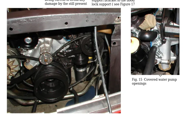
Fig. 15 Covered water pump openings
Fig. 16 Radiator, grill, hood latch, and fan removed
Proper disassembly is critical to the success of this project. Take time to carefully remove each component storing in a safe location.
shows two of the bolts). Now you can lift the entire grill out by tilting it slightly forward and lifting straight up. There is no need to remove any of the chrome pieces that decorate the from of the grille or sur-round. However, if you need to do any grille resto-ration do it now. You can now fully remove the chrome horse and corral if desired and repaint the grille if required.
Be sure and cover the water pump inlet and outlet with plastic tape to prevent a stray socket or nut from flying in and potentially ruining your water pump ( see Figure 15 ). move the clamp at the
ra-diator and at the thermostat housing as shown in Fig-ures 13 and 14. You will have seen similar clamps on the bottom radiator hose. Remove both hoses completely.
Now you are ready to re-move the radiator itself. If your radiator has a cowl you must remove its mount-ing screws and the 4 radia-tor mounting nuts position on each side of the radiator as shown in Figure 13. Carefully lift the cowl if present away from the ra-diator and rest it on the fan blade. Now you will be able to remove the radiator itself. Lift it straight out being careful to avoid any damage by the still present
fan blade.
Set the radiator aside. Once the radiator dries out a bit it will be a good time to give it a spray coat of high temperature gloss black paint. It is amazing how much better the radia-tor will look freshly painted when you re-install it. Now it is time to remove the front grill. The front grill can be removed easily by removing 8 hex head screws.
Start by removing the four screws from the lower inner flange of the grille. Next remove the four screws from the upper flange of the grille center support bracket to the hood lock support ( see Figure 17
Fig. 19 Fan retaining bolts Fig. 17 Grille retaining screws Fig. 21 Hood latch screws Fig. 20 Eaton power steering pump mounting bolts
Fig. 18 Alternator It is now necessary to
re-move the hood latch mechanism. Figure 21 shows 4 retaining screws you must remove. Once the latch is out you will see that a support bracket is secured by 2 retaining screws. One of these screws is removed from the front of the car. Once the hood latch sup-port bracket is removed you can restore these pieces with flat black paint so that they will look new when they are replaced at the end of our installation. Be sure and remove any rust if possible strip to bare metal before painting. Now you can more easily remove all of the belts. Remove the power steering belt first. You can com-pletely remove the adjust-ment retaining bolt ( Figure 20) as our next step will be to un-mount the power
steering pump.
Loosen the power steering pump mounting bracket bolts also in Figure 20. Remove the alternator belt by loosening the mounting and adjustment bolts as shown in Figure 18.
Store these belts as you will reuse them when reassem-bling the system.
Now remove the fan, spacer, and water pump pulley. These are held to-gether with 4 long bolts as shown in Figure 19. You will not reuse the fan but you must retain the spacer and water pump pulley.
Figure 16 gives you a good idea of what your car should look like now. You now have clear access to the area where you will install the condenser, dryer, and compressor.
Installation: Removing the Hood
Latch,Belts,and Fan
Fig. 23 Power steering pump removed with hoses intact Fig. 22 Air cleaner removed and carb. covered
Fig. 24 Repaint
Clean and paint your engine compartment as you proceed with the installation. You will be surprised how much bet-ter the overall installation will look.
Remove the air cleaner assembly and cover the carburetor. Opening. This is an important step as you don’t want any flying metal or loose nuts to fly down your carb. Remember to re-move the cover before you start the engine in any case.
Now remove the power steering pump by removing two retaining bolts and lock washers locates as shown in Fig-ure 23. The Eaton pump is quite heavy and you will want to keep the reser-voir as upright as possible to avoid spilling power steering
fluid.
After we have installed the compressor mounting bracket we will reinstall the power steering pump. In order to use the Eaton pump we will add stand-offs between the steering pump mounting bracket a the engine and also be-tween the pump itself and the mounting bracket. If you see old rust on the engine block repaint with a can of high heat Rust-0-Leam ( Figure 24 ). This is a good method to make your engine look freshly painted.
Installation: Removing the Power
Steering Pump
“Now remove
the power
steering pump
by removing
three retaining
bolts and lock
washers…”
Fig. 26 Power steering adjustment bolt
Fig. 27 Mounted compressor bracket Fig. 25 Water pump mounting bolts needing removal.
To prepare for mounting the compressor bracket you will need to remove 4 of the water pump mount-ing bolts as shown in Figure 25. and 26. below.
Since the power steering pump is now moved you can remove the power steering adjustment bolt shown in Figure 26. Remove this bolt com-pletely. This bolt is unusual in that it has a long
threaded end after the bolt
head so that the power steering adjustment bracket can be fixed with it and an additional nut. We will replace this adjustment bolt with a longer version later on since we have to relocate our Eaton power steering pump approxi-mately 2 inches forward ( towards the grill ) from where it is now.
A Ford power steering pump will most likely be able to use the existing ad-justment bolt.
Figure 27 shows the com-pressor mounting bracket installed.
We do not recommend you install the compressor mounting bracket at this point because other work needs to be done in the engine compartment and the bracket will just get in the way.
Your next step will move you into the interior of the car to prepare for the evaporator install.
Installation: Removing the Water Pump
Mounting Bolts
“We do not
recommend
you install the
compressor
mounting
bracket at this
point…”
Fig. 25 Seat mounting bolt holes Fig. 26 Original console mounting
Fig. 27 Seat removed
Proper disassembly is critical to the success of this project. Take time to carefully remove each component storing in a safe location.
Now we will take a break from the engine compart-ment and focus on prepar-ing the interior for installa-tion of the evaporator. Remove the driver seat by removing 4 retaining nuts from underneath the car. Figure 25 shows the most forward left hand location. These access holes may be covered by rubber grom-mets. Just peel off the grommet and back out each of the four nuts.
It is important to remove the front drivers side seat as it allows for much easier installation of the evapora-tor, cutting of the firewall hose slot, and installation of a shortened console if needed.
In addition you will need the room to install the evaporator hoses and add the evaporator fan and con-trol wiring.
Figure 27 shows the front seat completely removed
and the evaporator in place. Do not put the evaporator in place at this time as you will need to create the firewall slot and drill the evaporator drain hole first.
You can clearly see from the photographs how much more room is available for maneuvering once the from seat is removed. It is usu-ally not necessary to re-move the passenger side seat.
Installation: Removing the Front Seat
“It is important
to remove the
front drivers
side seat as it
allows for
much easier
installation of
the
evaporator.”
shown in Figure 29. These bolts are visible between the bumper and valence. Get under the car on each side near the parking lights to remove the 4 ( two each side ) retaining bolts that hold the valence to the from lower fender lip as shown in Figure 30.
Now the valence should come completely off as shown in Figures 31 and 32. Carefully store the valence to avoid denting or scratch-ing it. This metal is of course visible to the out-side world.
valence this is not a good idea for two reasons. First the dryer and condenser connections will not be easy to make and second it is important to have the valance removed during the R134A charging proc-ess so that leaks in this area can be easily identified. First remove the two chrome bumper guards as pictured in Figure 28. Each bumper guard is secured by two mounting bolts to the bumper supports. Now you can remove the 4 top retaining bolts from the front side of the valance as Removing the front valence
is the next important instal-lation step. Before remov-ing any body part or en-gine part that has been on the care since it was origi-nally built remember to soak with a good rust pene-tration fluid like WD40. It is best to spray on the fluid the day before you start disassembly and then again approximately 30 mins. before you actually start to loosen nuts and bolts.
While it may be possible to install the condenser and dryer without removing the
Fig. 31 valance retaining bolts on inside fender Fig. 30 inside fender bolts
Fig. 32 Valance removed Fig. 29. Valance retaining bolts
Fig. 28 Chrome bumper guard
“Carefully
store the
valence to
avoid denting
or scratching
it.”
Fig. 29 Automatic shifter removal Fig. 28 Original console mounting
Fig. 30 Original console mounting screws
Review the entire instal-lation procedure care-fully before beginning. before
If your car is equipped with a center console it must be removed in order to install the evaporator and lines to the compressor and dryer.
Remove the shifter handle with an allen wrench as shown in Figure 29. Remove the six console mounting screws ( 3 each side ) illustrated in Figure 30.
Open the console door and remove the two mounting screws which attach the console to its support bracket.
Now you will be able to carefully remove the entire console. Since the front seat is removed this is now much easier to accomplish. As you slide the console over the shifter move the shifter in to its most rear-ward pointing position. You will have to carefully
angle the console to re-move it completely. As you remove the console you will notice that a wiring harness is in place that pro-vides power for lighting the rear passenger courtesy lamps. Un plug the quick-disconnects as you remove the harness. You will then be able to freely move the console.
Handle the console care-fully it is usually somewhat
Installation: Remove Center Console
and Shifter Handle
“Handle the
console
carefully it is
usually
somewhat
brittle with
age.”
Fig. 33 Lower ra-diator support dim-ple location
Fig. 31 Upper radiator support dimple location
Fig. 32 Upper radiator support dimple loca-tion—close up
Review the entire instal-lation procedure care-fully before beginning. before
Disassembly of the car in preparation for installation of the major components is now complete.
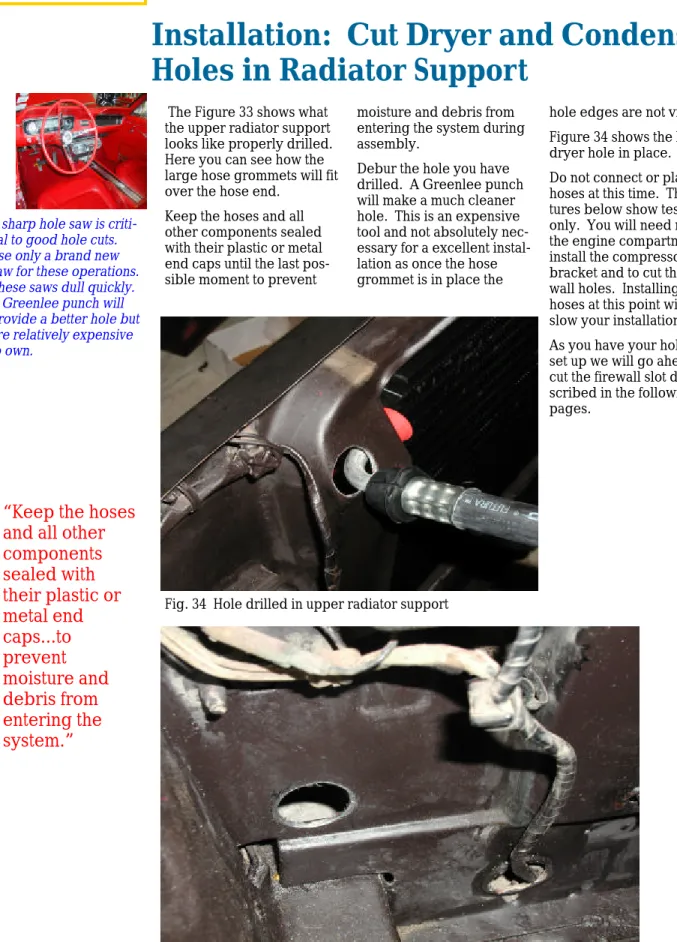
Now you will start on cut-ting the condenser/dryer line holes using a hole saw or a Greenlee punch. The dryer and condenser holes we describe here are cut at 1 1/4 inches diame-ter.
Use a brand new hole saw and drill a 1/8 inch pilot hole before you start cut-ting with the hole saw. You will make the upper radia-tor support hole by drilling
from inside the engine compartment.
The hole location is indi-cated by small dimples made at the Ford factory on the radiator support frame ( drivers side ). Figure 31 shows the approximate position of the upper hole which provides a opening to pass the compressor to the condenser line fittings. This dimple may be hard to locate but the Figures 31 and 32 should give you a start on locating and check-ing their position.
After the top hole is drilled
use the same procedure to drill the lower support hole. Again it is drilled at 1 1/4 inches diameter. The location of the lower hole is critical as the right angle dryer connector must connect to the bottom of the dryer and go through this hole to meet up with the aluminum line which makes its way to the evaporator. This is a great opportunity to clean and paint any of the radiator support assem-bly in order to get that fac-tory fresh look.
Installation: Cut Dryer and Condenser
Holes in Radiator Support
“Use a brand
new hole saw
and drill a 1/8
inch pilot hole
before you
start cutting
with the hole
saw.
Fig. 33 Hole drilled in lower radiator support Fig. 34 Hole drilled in upper radiator support
“Keep the hoses
and all other
components
sealed with
their plastic or
metal end
caps...to
prevent
moisture and
debris from
entering the
system.”
A sharp hole saw is criti-cal to good hole cuts. Use only a brand new saw for these operations. These saws dull quickly. A Greenlee punch will provide a better hole but are relatively expensive to own.
The Figure 33 shows what the upper radiator support looks like properly drilled. Here you can see how the large hose grommets will fit over the hose end.
Keep the hoses and all other components sealed with their plastic or metal end caps until the last pos-sible moment to prevent
moisture and debris from entering the system during assembly.
Debur the hole you have drilled. A Greenlee punch will make a much cleaner hole. This is an expensive tool and not absolutely nec-essary for a excellent instal-lation as once the hose grommet is in place the
hole edges are not visible. Figure 34 shows the lower dryer hole in place. Do not connect or place any hoses at this time. The pic-tures below show test fitting only. You will need room in the engine compartment to install the compressor bracket and to cut the fire-wall holes. Installing the hoses at this point will just slow your installation. As you have your hole saw set up we will go ahead and cut the firewall slot de-scribed in the following pages.
Installation: Cut Dryer and Condenser
Holes in Radiator Support
Fig. 37 How the bracket will look when mounted Fig. 35 Firewall slot
Fig. 36 Firewall grommet
Be sure and debur the slot completely. The slot should allow the stepped edge of the rubber grom-met ( see Figure 36) to fit closely. However you should be able to insert the grommet in the slot and it should stay in place without undue warping.
Fig. 36 Interior insulation
Hole spacing is 1 3/4 inches
In order to cut the firewall slot you must first remove the driver side brace. This is accomplished by remov-ing the retainremov-ing bolts at the firewall and at the shock tower.
Figure 37 shows the brace moved. This figure also shows the firewall grommet and bracket installed. To illustrate what your system will eventually look like. Do not attempt to route the evaporator lines or grom-met at this time however as doing so will cause you extra work.
From inside the car just above the gas pedal you will notice an oblong cutout in the firewall insulation material.
This plug is easily pulled out and looks like Figure 36. In newer cars a knock-out is present in the fire-wall. However, in very early cars you must manu-ally cut the slot opening. You will make the slot by cutting two 1 1/4 inch. Holes and using a hacksaw blade or a metal nibbler to cut the intervening metal. The holes must be spaced
approximately 1 3/4 inches apart and fit within the cut-out area designated by the insulation cutout location. Be carefully when cutting the lower hole as a brake line on many cars comes very close to the edge of this hole. In our sample installation we had to loosen the mounting bracket for this line to en-sure it would not be cut during drilling of the lower hole.
Test fit the grommet to make sure that it fits snugly in the slot you have made.
Fig. 42 New crankshaft pulley installed Fig. 41 New crankshaft pulley installed
Fig. 40 Old and new crankshaft pulleys
Fig. 44 Old crankshaft pulley installation
Fig. 43 Crankshaft pulley installation
Always soak old fasten-ers 24 hrs before at-tempting to loosen with penetrating oil . If the fastener is rusted it will be frozen in place and weakened by the rust. In this case you may easily break a bold head or round a nut off.
If you have followed our advice you have already sprayed liberal amounts of rust penetrator on the crankshaft pulley bolts 24hrs. in advance of actu-ally applying pressure to remove. Now give a sec-ond blast of the oil and after at least 30 mins. to allow the penetrator to work remove the three 3/8” crankshaft bolts.
After you remove the bolts you will most likely find that the pulley is still fastened to the crankshaft. This is usu-ally because of a tight fit-ting lip that fits into a groove on the harmonic balancer. Give this area a
good shot of penetrating oil as indicated in Figure 43. Now you can knock the crankshaft pulley off of its groove/lip mounting by tapping it around the radius of the part.
Once you have the part removed clean the har-monic balancer face care-fully.
Any debris between the crankshaft pulley and the harmonic balance will cause the crankshaft pulley to wobble when in motion. Coat the back of the new crankshaft pulley shown in Figure 40
with anti-seize compound or a thin coating of lithium grease to prevent binding in case you ever have to remove the pulley for any reason.
Now tighten the 3, 1-1/4” bolts provided in a cross wise pattern to ensure even clamping.
Your crankshaft pulley should appear as shown in Figures 41 and 42 when properly installed.
Your pulley may be either a die-cast component or stamped metal one.
Fig. 45 Compressor Mounting Bracket Installation
Installing the compressor bracket may require modification to the bracket itself. Carefully test fit the bracket before securing it to the engine.
You will now install the compressor mounting bracket. Start by removing the three top most mount-ing bolts in your water pump if you have not al-ready.
You should now have the power steering pump loose and off of the engine block. The bracket shape you have may vary depending on whether you have an Eaton or Ford power steer-ing pump.
Installing the compressor bracket is the most difficult part of the entire assembly process.
There are so many combi-nations of engine configu-rations that you may have to
modify the bracket you received from CAA to have it fit properly on your car. In our sample installation case we had to enlarge the holes in the bracket where the 3/8” nuts mount. The compressor bracket utilizes three bolts that hold the water pump together plus the two bolts that held the power steering pump in place.
Test fit the bracket carefully before first installing the three water pump bolts. Do not install the (2) 3/8 inch bolts that mount the power steering pump bracket ( not show ) at this time as you will need to leave the power steering
pump off until later in the assembly process. Note that we have already assembled the idler pulley and eccentric arm visible in Figure 45.
Use the 3/16 inch spacers provided by CAA to ensure that the bracket will mount squarely against the water pump and engine block. In the case of the Eaton power steering pump these spacers will go behind the compressor mounting bracket next to the engine block.
The power steering pump bracket will go on top of the compressor bracket with additional spacers to provide proper alignment
Installation: Adding the Compressor
Mounting Bracket
Fig. 46 Power Steering Pump Bracket Mounting Holes in Block
Fig. 47 Compressor Mounting Bracket Installed Top View
for the belts.
Make sure and use the pro-vided lock nuts on all of these bolts.
Do not fully tighten the idler pulley eccentric arm. Simply finger tighten its mounting bolt to hold it in place during assembly. Test fit the compressor and make sure that its pulley lines up with the outermost groove on the crankshaft pulley ( see arrow in Figure 47).
Be careful when you lift the compressor and keep its dust caps on until just be-fore you hook up the lines as described further on.
Installation: Adding the Compressor
Mounting Bracket
“Be careful
when you lift
the
compressor
and keep its
dust caps on
until just
before you
hook up the
lines…”
Mounting of eccentric arm and idler pulleymust be used between the pump adjustment bracket and the engine block. This is because the Eaton Power steering pump must be pushed out in order for the belt to align with the mid-dle groove of the crank-shaft pulley and the outer groove of the water pump
pulley.
Fig. 49 Power Steering Pump Bracket
Fig. 50 Power Steering Pump Bracket Fig. 48 Power Steering Pump Bracket
Carefully test fit the bracket before securing it to the engine.
Two standoffs go here between mounting bracket and pump Two standoffs go here
be-tween mounting bracket engine block
The Eaton power steering pump is mounted with two bolts to the adjustment bracket. This bracket is secured to the engine block with two additional bolts.
Figure 45 shows the loca-tion of the adjustment
bracket mounting bolt holes. In the figure the up-per hole locates the pivot point for the pump adjust-ment. The lower slotted hole allows movement of the bracket and pump for belt tensioning.
Two 1 1/8 inch standoffs
Installation: Remounting the Power
Steering Pump
tension later on in any case. Make sure that the bolts that hold the power steer-ing pump to the mountsteer-ing bracket are secured. Tight-ening later on in the assem-bly process will be more difficult.
ment bolt.
As you can see in Figure 51 we mounted a threaded 5/16 inch standoff on this bolt to strengthen it a bit. We then used two nuts and a lock washer to act as the retainers for the power steering pump adjustment arm.
Once the power steering pump is properly installed its pulley should line up with the middle groove of the crankshaft pulley. Carefully test alignment of these pulleys before clamp-ing down the adjustment bracket arm or the pivot point for the power steering pump bracket.
You will have to adjust the power steering pump belt Additionally the pump itself
must be mounted at the adjustment bracket on 1 inch standoffs. These standoffs are shown in Fig-ures 52 and 53. The 5/16 inch bolts that go in these positions must be longer than standard to accommo-date the added standoffs. The standoffs for the bracket and steering pump mounting may not be in-cluded as part of the CAA kit. We created our stand-offs by cutting steel tubing to length.
Please note that before you mount the pump you must install the power steering adjustment bolt. This bolt doubles as a fastener for the water pump.
Purchase a length of 5/16 inch threaded rod and cut to length approximately 3 inches longer than the bolt that originally mounted the water pump and acted as the power steering
adjust-Fig. 53 Power steering bracket and pump standoffs Fig. 51 Power steering water pump
adjustment bolt. View down from top of engine. Fig. 52 Power steering pump standoffs
Water pump pulley
“Please note
that before you
mount the
pump you
must install the
power steering
adjustment
bolt.”
Installation: Remounting the Power
Steering Pump
Now you will install the evaporator lines and fire-wall grommet/bracket. Do not secure the evapora-tor in place at this time. However you may wish to place it in the car in its gen-eral location to judge just how far into the car to place the evaporator lines. In the example installation two lines go to the evapora-tor. The larger diameter line goes from the lower evaporator connection to the compressor.
The smaller diameter line is connected to an aluminum line which goes to the bot-tom of the dryer receiver as shown in Figure 51. First position the grommet in place under the grommet bracket and mark hole lo-cations for the mounting ears.
Drill the mounting holes but do not mount the brackets around the grommet at this time..
Push the hose approxi-mately 2 feet through the grommet.
Now that the smaller ( evaporator to aluminum dryer line ) hose is fed through the grommet mount the grommet behind the bracket. Make sure that the smaller diameter hose Next you will feed the
smaller of the two hoses through the grommet. This takes some doing and it will help to coat the grommet with some “ArmorAll” or other similar rubber/vinyl preservation product. Don’t use any sort of oil since oil can destroy rub-ber products.
Fig. 56 Evaporator lines in place Fig. 54 System line connections
Fig. 55 Evaporator lines in firewall grommet
The firewall grommet is critical to prevent engine smells and sounds from entering the passenger compartment.
Installation: Route Evaporator Lines
and install Firewall Gasket and Bracket
“..it will help
to coat the
grommet with
some
“ArmorAll” or
other similar
rubber/vinyl
preservation
product.”
connections. It is best to use a set of flare wrenches for this task.
Note that we have moved the driver side firewall to shock tower brace moved out of the way for installa-tion of the grommet and lines ( see Figure 58). If your car is equipped with a an export brace you will have to remove it entirely. It may also be necessary to remove the brake vacuum hose shown in Figure 52 in order to gain access to the grommet area. This is the vacuum line from the mani-fold to the master cylinder.
It is best to remove this line at the master cylinder end only and move the line out of the way for installation.
rator control line which we will run later.
Now pull the hoses into position and loosely con-nect to the evaporator. Before connecting the hoses to the evaporator or any other component be sure and apply a single drop of 3 in 1 oil to the mat-ing surfaces. If an O rmat-ing is used on that connection soak it in the oil before in-stallation.
In the next section we will mount the evaporator. Af-ter mounting is complete tighten the evaporator line
Fig. 58 Evaporator lines in firewall grommet Fig. 57 Evaporator lines in firewall grommet
To Compressor
To Aluminum Line is mounted on the bottom.
This will keep the compres-sor and aluminum hose lines parallel in the engine compartment. Note that the lines “cross” inside the car as shown in Figure 56. This will result in an overall better appearance in the engine compartment of the installation.
Push the larger diameter hose through the mounted grommet after coating the hole with “ArmorAll”. Figure 57 shows the mount-ing screws and both lines inserted. The middle very small hole is for the
evapo-Installation: Route Evaporator Lines
and install Firewall Gasket and Bracket
“Note that we
have moved
the driver side
firewall to
shock tower
brace out of
the way for
installation of
the grommet
and lines…”
evaporator until it is straight with the face of the dash.
Now you can tighten the bolts that secure the evapo-rator mounting ears. Use a 1/4 inch open ended wrench to tighten the bolt so that the evaporator is lifted off of the transmission hump with at least 1/4” inch clearance.
Now tighten the securing nut as in Figure 57. You can now also connect the wiring harness pro-mately 1 inch loosely
atta-ché the securing nut pro-vided by CAA. See arrow in Figure 61.
Now you can position the evaporator and attach it to the two mounting holes that are under the dash already present in your car ( see Figure 56).
First though connect the compressor and dryer lines that you pulled in from the engine compartment and tighten.
Adjust the position of the Mounting the evaporator is
a simple task. Requiring only three bolts. Before you mount the evaporator insert the level-ing bolt as shown in Figures 59 and 61.
The leveling bolt is crucial to a good installation and proper evaporator fan life. Thread the bolt in from the top until it extends about 1 inch below the threaded nut shown in Figure 59. When this bolt in is place and extended
approxi-Fig. 61 Evaporator back view showing leveling g bolt Fig. 60 Evaporator front view showing mounting ears Figure 59
The firewall grommet is critical to prevent engine smells and sounds from entering the passenger compartment.
Remove this nut before threading bolt into evaporator leveling bracket.
Installation: Mount Evaporator and
Adjust Leveler Bolt
Fig. 62 Evaporator front view showing mounting vided by CAA to the evapo-rator.
This wiring harness has two connections. One which exits through the firewall grommet and the other which provides power to the evaporator controls and fan.
Looking at the harness the yellow wire should be con-nected to a fused positive power point on your fuse box. The black wire will travel through the firewall plug ( centered between the evaporator lines) di-rectly to the compressor clutch power connection.
Fig. 63 Evaporator rear view with leveling bolt in place.
Yellow wire to 12 V
source on fuse block Black wire to
compressor
Installation: Mount Evaporator and
Adjust Leveler Bolt
Figure 66 compressor rear mount Figure 67 compressor in place Figure 65 rear compressor mounting
Figure 64 compressor mounted
Now we an feel like real progress has been made. We are mounting the compressor!
Refer to Appendix B for instructions on mounting an original York type pressor. The Sanden com-pressor we received from CAA comes pre-charged with oil so there is not need to open the oil access plug. Keep the compressor sealed by leaving on the dust caps during the
mounting process. The compressor mounts with (4) 3/8 inch bolts pro-vided by CAA.
Figure 64 shows the instal-lation. The compressor is shifted slightly forward on the bracket by the two 3/4 inch spacers that are mounted behind the front ears.
Be sure and include lock washers as shown in Figure
68.
After you have the com-pressor secured connect and tighten the larger of the lines coming from the evaporator.
Be sure and use a drop of 3 in 1 oil on the mating joints for these connections. Soak any O-rings in this oil be-fore installation. Tighten this connection firmly. Handle the compressor with care as it is quite heavy.
Tighten all mounting bolts but do not however connect the wiring harness clutch control wire to the com-pressor at this time. Figure 38 gives a good idea of how the spacers lock-washers and nuts are util-ized in this assembly.
Figure 68 compressor mounting
Installation: Mounting the Compressor
“Handle the
compressor with
care it is quite
heavy. Tighten all
mounting bolts but
do not connect
the ...clutch control
wire…”
washers for reference. These will be applied from the engine side of the ra-diator when the rara-diator is installed.
Now mount the dryer as shown in Figures 72 and 73. You will connect the dryer to the condenser first ( Fig-ure 73) and then attach the mounting strap hardware shown in Figure 72. Once the dryer is in place test fit the condenser again to ensure that the brackets properly line up with the existing radiator mounting holes. You do not want to have to adjust the positions of these brackets once the radiator is in place. Once the dryer is installed leave the remaining dryer dust cap and the condenser dust cap in place until just before you attach the lines.
This will prevent debris and mois-ture from entering the dryer.
The dryer nection to the con-denser should be tightened firmly at this point. Make sure that the dryer exit tube and con-nector is parallel to the condenser as shown in Fig-ure 74. Tighten the mounting strap with the CAA fur-nished screw and you are ready to mount the con-denser. Figure 71 Condenser to dryer
assem-Figure69 and Figure 70. Condenser mounting brackets.
The dryer should be kept sealed until the last pos-sible moment. It contains a desiccant which can absorb waterl
Assemble the 4 condenser mounting bracket as shown in Figure 69,70, and 71. The brackets are somewhat adjustable so you should only loosely attach the brackets and test fit on the car.
Do not over tighten the bracket mounting screws. It is easy to strip out the
sheet metal holding the condenser coils together. Figure 71 shows the radia-tor side of the condenser. Note that the mounting bolts used to secure the radiator are now part of the condenser mounting brack-ets.
Figure 70 shows the mount-ing nuts with integral lock
Installation: Assembly of the
Condenser and Dryer/Receiver
Figure 72 and 73 condenser to dryer assembly
Figure 74 Condenser to dryer assembly
Installation: Assembly of the
Condenser and Dryer/Receiver
“The dryer
connection to
the condenser
should be
tightened
firmly at this
point. Make
sure that the
dryer exit tube
and connector
is parallel to the
condenser...
CAA.
Slide the condenser/dryer assembly into place, and insert the condenser bracket studs through the radiator mounting holes as shown in Figure 79. The condenser bracket studs also secure the cowl to be installed later.
Tighten the line at the com-pressor end ensuring that you have applied 3 in 1 oil to the joint and soaked any O-rings before assembly. Do not use an excessive amount of oil.
The discharge hose con-nector should also be pro-tected by a large rubber grommet provided by Before mounting the
con-denser dryer assembly connect the compressor to condenser line also known as the “discharge hose”. Figure 75 shows the posi-tion of this hose. Figure 76 shows routing through the hole you previously made in the radiator support frame.
Figure 76 condenser to dryer assembly Figure 77 condenser to dryer assembly
Figure 75 condenser to dryer assembly
Carefully handle the dis-charge hose and all other hoses as you are install-ing them to avoid nicks or cuts during handling.
Installation: Mounting the Condenser/
Dryer Assembly
Figure 79 condenser to dryer assembly Figure 78 condenser to dryer assembly
moved during charging of the system so leaks in the bottom of the receiver/ dryer area can be checked.
Always tighten these con-nections with two wrenches to ensure that the soft tubing to coupler-joints are not cracked.
Figure 80 condenser to dryer assembly After lowering the
con-denser in place be sure and attach the right angle con-nector to the bottom end of the receiver dryer.
You will have to access this connection from the front of the car as you have
re-moved the valance previ-ously.
Install the second large rubber grommet as shown in Figure 78 and 80. Note: in the pictures below that the dust caps are in
place during installation as long as possible to keep debris and water out of the system.
Make sure the right angle joint and the compressor connections are firmly tightened.
Do not reinstall the valance at this time. It is important to have the valance