SPACE SHUTTLE PROPULSION SYSTEMS PLUME MODELING AND SIMULATION FOR THE LIFT-OFF COMPUTATIONAL FLUID DYNAMICS MODEL
L.L. Strutzenberg ^, N.S. Dougherty*, P.A. Liever +, J.S. West ^A, and S.D. Smith _ Marshall Space Flight Center
Huntsville, Alabama ABSTRACT
This paper details advances being made in the development of Reynolds-Averaged Navier-Stokes numerical simulation tools, models, and methods for the integrated Space Shuttle Vehicle at launch. The conceptual model and modeling approach described includes the development of multiple computational models to appropriately analyze the potential debris transport for critical debris sources at Lift-Off. The conceptual model described herein involves the integration of propulsion analysis for the nozzle/plume flow with the overall 3D vehicle
flowfield at Lift-Off. Debris Transport Analyses are being performed using the Shuttle Lift-Off models to assess the risk to the vehicle from Lift-Off debris and appropriately prioritized mitigation of potential debris sources to continue to reduce vehicle risk. These integrated simulations are being used to evaluate plume-induced debris environments where the multi-plume interactions with the launch facility can potentially accelerate debris particles toward the vehicle.
INTRODUCTION
As a part of the Return-To-Flight (RTF) effort, the Space Shuttle Program undertook the effort of identification, control and residual risk assessment for every possible source of debris that could be liberated during Lift-Off and Ascent of the Space Shuttle Vehicle (SSV). At that time, the OVERFLOW Computational Fluid Dynamics (CFD) [1] program and Chimera grid approach had been at use at NASA/JSC to simulate the flow over the integrated SSV for over 16 years. These simulations were significantly refined in support of the RTF effort and were used as the basis for ascent debris analysis [2]. As a part of the RTF effort, NASA/MSFC was tasked to analyze the potential debris transport during the Lift-Off portion of the flight regime. The Lift-Off timeframe begins with the start of tanking and ends when the vehicle clears the tower and falling debris from the fixed service structure (FSS) can no longer have a transport path to the SSV.
To accomplish the Debris Transport Analysis (DTA) for identified Ascent and Lift-Off debris sources, potential debris particles were 'flown' through a steady-state CFD solution representing an instant of time in the launch and flight sequence. Numerical simulations included steady-state Reynolds-Averaged Navier-Stokes (RANS) analysis of the entire SSV and, for Lift-Off, of the SSV plus pertinent launch facility structures. Modeling and analysis for ascent and Lift-Off utilized NASA's OVERFLOW code and overset grid techniques in the Chimera Grid Tools [1] package. Using the same tools and methodologies provided the opportunity to streamline the process and provide results in as timely a manner as possible as well as the ability to
demonstrate consistency of analysis between the Lift-Off and Ascent teams. The set of Lift-Off Debris DTA solutions thus obtained are referred to as Cycle-1 and have been previously reported. [3]
* Senior Engineer, Jacobs ESTS Group, ERC/MSFC ^ Lead Engineer, NASA/MSFC/MP71
^^ Lead Engineer, NASA/MSFC/ER43 ÷ Senior Engineer, CFDRC/MSFC # Senior Principal, Plumetech/MSFC
TheCycle-1resultsprovidedaneffectivescreening
of thepotentialdebrissourcesand
providedinsightintothecriticalshortcomings
oftheCycle-1conceptual
andcomputational
modelstoaddresstheLift-Offdebrisrisk. ItwasclearthattheCycle-2modelhadtoinclude
significantreductions
inuncertainty
in boththeCFDandDTAaspectsofthesimulations
to
addresstheLift-Offdebrisriskfromplumedrivensourcesin
a meaningful way. In addition, the integrated model was expanded to address the inherent environmental uncertainty for wind driven debris explicitly by incorporation of the Shuttle ground winds model.TOOLS, MODELS, AND METHODS LIFT-OFF DEBRIS TRANSPORT ANALYSIS PROCESS
The Lift-Off DTA (LODTA) process consists of two steps: (1) producing steady-state CFD flowfield simulations of the SSV on the launch pad with and without exhaust plumes, and (2) post-processing of gravity, wind and plume-driven debris particle trajectories through the flowfield. It is necessary to have CFD simulations for times in the launch sequence prior to Lift-Off as well as during Lift-Off. This includes pre-launch during tanking operations when ice or other falling debris might impact the vehicle due to transport under the influence of gravity and ground winds. CFD simulations include possible variations in ground wind speed and direction approaching the launch pad. Other major events represented in the time slices chosen for the CFD solutions include Main Engine Start at the time when the three Space Shuttle Main Engines (SSMEs) have reached 100% power level, Solid Rocket Booster (SRB) Ignition at the moment of reaching full SRB thrust just as the vehicle lifts off, and a matrix of quasi steady-state simulations during 'climb out' as the SSV rises from the Pad until 'Tower Clear'. Plume aspiration and ground wind effects are implicitly captured in Engine Start, Lift-Off and Climb-Out CFD simulations. Plume aspiration may accelerate falling debris to impact on the vehicle.
Virtual simulations of debris particle trajectories in each CFD flowfield involve particle release inside a steady-state fiowfield and calculation of particle flight trajectories. Many potential debris trajectories can be run from given sources in a CFD simulation with variations in release conditions applied. The result of the process is a set of possible particle impact locations with corresponding kinetic energy and angle with respect to the impacted surface.
INITIAL CFD MODEL (CYCLE-I)
The Cycle-1 Lift-Off CFD model adopted both the computational grid and the finite-volume flow solver OVERFLOW that are being used in Ascent DTA (Figures 1-3). Directly adapting the existing Ascent CFD model by adding the launch facility grids was selected as the most reasonable approachto support RTF. This initial DTA model was used to screen all expected debris sources for impact potential.
A number of simplifications were required to complete the Cycle-1 CFD and DTA. These included: 1) quasi steady-state approximation; 2) use of a single fluid species (perfect gas air with _,=].4) to model air and the SSME and SRB plume effluents; 3) significant de-featuring of the launch facility structure surface details; 4) omission of sound and ignition overpressure
suppression water bags and sprays; 5) simple slug flow ground wind profile and omission of the Fixed Service Structure (FSS) wind blockage effects; and 6) debris code limitations including 3-DOF (drag only) aerodynamic characteristics used for the debris particle tracking and 7) use of a simple rebound model with a single Coefficient of Restitution (CoR).
Figure 1. Pressure Coefficient on the Space Shuttle Launch Vehicle and in the Near-Body Flowfield [4]
Liftoff and TO+1.9s
Figure 2. Cycle-1 Shuttle Lift-Off CFD Model
The Cycle-1 results indicated that the most dangerous class of debris during Lift-Off is plume-driven. It is therefore imperative to accurately model the plume structure and interaction with the launch facility. The Overflow CFD code could only model the SSME Mach disk at first order spatial accuracy instead of the desired second order. Additionally, an appropriate
thermodynamic model plume effluent proved to be non-robust. Therefore the decision was made to use air for both SRB and SSME plume effluents. This approximation introduced significant error and uncertainty into the plume definition [5] and the subsequent predicted debris trajectories. In addition, many of the potentially dangerous plume-driven trajectories include rebound of the debris particle, either from Mobile Launch Platform (MLP) structure, vehicle structure or both. Cycle-1 employed a single CoR for each debris source material, independent of target material or velocity at impact. Because inelastic collision effects were not considered, the CoR value of 0.5 that was employed for Cycle-1 DTA significantly over-predicted rebound at high velocities [6].
MODEL IMPROVEMENTS - CYCLE-2
MSFC PSE&I has sponsored multiple Cycle-2 Lift-Off CFD and DTA tool enhancements [7] to capture the physics of plume-dominated launch pad flowfield analysis and debris trajectory
prediction more accurately. The Cycle-2 model developed is the result of the convergence of multiple complementary efforts including:
Unstructured grid CFD code, Loci-CHEM [8, 9, 10] and grid generation tool,
SolidMesh/Advancing Front Local Reconnection (AFLR) [11, 12, 13], enhancements for massively parallel processing of large CFD models.
Rebuilding and refining LODTA CFD models with unstructured grids.
Demonstration of MLP-SRB plume interaction with detailed facility geometry and realistic plume gas.
Assembling the complete SSV/Launch Pad CFD model and establishing best practices for grid generation and CFD analysis.
Verification and Validation of the Loci-CHEM CFD code for plume flowfield simulations. • Adaptation of the DTA tools to process unstructured grids.
• Incorporation of an experimentally validated rebound model into the DTA tool.
• Incorporation of a "database-driven 6-DOF" capability for calculation of debris trajectories including lift forces in addition to drag forces.
The first five elements outlined above comprise the tasks necessary to develop and integrate the CFD model required for the Cycle-2 DTA, and constitute the focus of this paper. The last three elements were required for implementation of the DTA tool using the CFD model as a basis. These will be discussed in detail in a subsequent publication.
The primary objective for Cycle-2 LODTA is to remedy the shortcomings in the plume definitions. This entailed increasing the fidelity of the geometric model of the launch pad, providing a more accurate model of the SRB and SSME plume effluents, and resolving the gradients in the plume regions to a significantly better degree than that obtained previously. The Loci CHEM code is used in the Cycle-2 Lift-Off CFD model implementation. This tool allows unstructured computational grids to be used as well as more physically realistic gaseous properties. Unstructured grids require less time to create accurate models of detailed geometry than the block overset grids used by the Overflow CFD code. Also, unstructured grids allow the placement of grid cells in areas of high solution gradient, via existing solution adaptive refinement capability, making them more efficient in terms of computer resource allocation.
MODELING APPROACH AND DESIGN
To most efficiently and effectively apply the modeling resources available to the specific debris transport cases of highest concern, a three-level modeling approach was taken. This approach consisted of developing three complementary models with varying levels of fidelity and scope. Specifically:
(1) A full 3D model of the overall flowfield where potential particle trajectories may be tracked to impacts anywhere on the Orbiter, External Tank (ET), or SRBs.
(2) A more-detailed model of a single SRB exhaust plume through the SRB exhaust hole contains higher geometric feature details and a more faithful representation of the Approved for public release; distribution is unlimited.
SRB plume interactions with the holddown post/haunch structure. This model will primarily be used to determine effects of geometrical asymmetry in the SRB hole or asymmetry with respect to vehicle position on the development of the dominant flow features in the region.
(3) A symmetric-half SRB plume model with structural details including all of the surfaces on which the SRB plumes impinge in the exhaust hole and significant features of the MLP deck geometry, Structural details from both sides of the SRB hole have been included in the model.
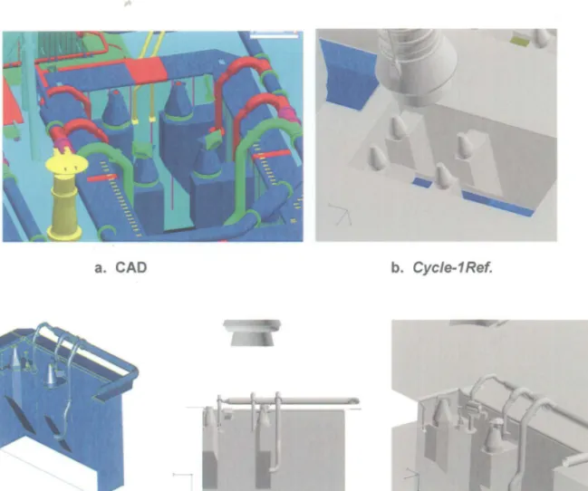
The higher resolution detail in the SRB exhaust holes comes at the cost of carrying a large number of grid cells in the CFD flowfield analysis. However, sufficient topological detail had to be included in each model so that potential debris items propelled by the SRB plume can be traced accurately through their trajectories, which may include multiple rebounds from structures in and around the SRB exhaust holes and on the MLP deck. The Cycle-1 definition of the MLP structure was kept to the essential minimum. SRB exhaust holes featured only the hold-down posts atop the hold down haunches, which were considered the essential flow blockage elements for a first-cut model. Refinements in the fidelity of features in the SRB exhaust holes became more important in light of the plume driven debris being identified as the most critical debris risks. Plume impingement, upwardly directed flow and rebound of debris items off the launch pad .
..
a. CAD
c. Cycle-2 (Detailed)
b. Cycle-1 Ref.
Figure 3. Facility SRB Exhaust Hole Geometry Modeling
structures had to be modeled accurately to fully assess the plume driven debris transport. In particular, the MLP blast deflectors, water pipes and hold-down post blast shield covers were significant details which were required to be included. On the left Figure 3a is the reference Computer Aided Design (CAD) MLP model. Figure 3b shows the Cycle-1 SRB exhaust hole geometry, and Figure 3c depicts the Cycle-2 symmetric-half model with grid detail enhancements
This approach allows a debris particle trajectory started in either the single-SRB or symmetric-half SRB model to be continued in the full-3D CFD solution. The full-3D CFD solution includes SSV geometric detail required to determine and characterize potential debris impacts. Another benefit of this three-tiered modeling strategy is the capability to efficiently investigate the effects of vehicle drift on potential debris transport.
MODEL DEVELOPMENT, IMPLEMENTATION AND INTEGRATION
Full 3D Lift-Off Model
Ground Plane and Structures Definition
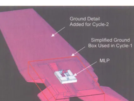
In addition to the enhancements to the detailed models of the SRB exhaust hole geometry, major upgrades and additions were made to the launch complex ground details including placement of the MLP on top of a detailed hill and farfield ground model. Figure 4 shows the differences between the Cycle-1 ground model, the "box-in-space" and the detailed launch complex topology included in the Cycle-2 integrated model.
Figure 4: Comparison of Cycle-1 and Cycle 2 Ground Modeling
The final Cycle-2 LODTA model outer boundaries extend outwards to one half mile in all four wind directions. Proper boundary layer wind profiles were imposed on these boundaries based on the Shuttle ground winds models [14]. Imposing the farfield atmospheric boundary layer flow Boundary Conditions (BC's) and directly computing the flow up and over the complex hill adds significant realism to the Cycle-2 simulations. The complex hill shape with various
vertical wall cutouts and ground operations buildings is likely to have an effect, particularly for pre-launch wind flow simulations.
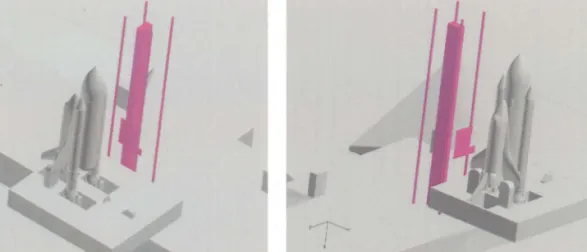
The most significant structure affecting the wind flow over the SSV is the Fixed Service Structure (FSS), which was not modeled in the Cycle-1 simulations. The structure is extremely complex in its details and cannot be easily or economically included in the CFD model. The approach taken for the Cycle-2 representation of the FSS provides for incremental inclusion of the major bulk structure components. At this time, the FSS elements included are the elevator shaft, the FSS corner posts and a plate representation of the retracted Orbiter Weather Protection (OWP) screen structure as shown in Figure 5.
,...-;- ...
I
.
Figure 5: Cycle-2 Full 3D Model FSS Representation
Five Plume Definition and Integration SSME Plume Definition
The sea-level SSME plume structure is dominated by the effects of its prominent Mach disk located just downstream of the nozzle exit plane. The post Mach disk conditions dominate the plume internal structure for the entire plume extent until impingement on the pad structure. The extreme shock jump conditions across the Mach disk present a severe computational challenge to the prediction of this shock structure and strength, and the subsequent large change in pressure, temperature and momentum downstream of this shock. In fact, the need to simulate the SSME Mach disk effects accurately is one of the drivers which prompted the change from the Overflow CFD program to the Loci-CHEM program. The crucial first task was therefore to
demonstrate that the Loci-CHEM code could reliably and robustly simulate the flow physics of both the SSME and SRB plumes.
First, the correct SSME outer mold line starting from the combustion chamber, throat, nozzle, aft manifold and external surface was ascertained. Previous simulations had used partially incorrect SSME geometry input. The SSME Outer Mold Line (OML) geometry utilized in this report has now been fully documented and is traceable to original SSME Block II design drawings [15].
An axisymmetric CFD model of the SSME plume at sea-level was created for the verified geometry. The model was applied in a series of parametric analyses to establish best practices for capturing the plume features. This screening included Loci-CHEM implementations of fluid physics modeling, chemical reactions modeling, turbulence modeling, grid structure, and case execution best practices.
Earlyin itsdevelopment
process,theLoci-CHEM
codehadbeenappliedsuccessfully
by
NASA/SSC
engineers
in attempts to model sea level SSME plumes. These simulations had been performed for inviscid flows, without turbulence modeling. Since the Loci-CHEM CFD program has changed significantly, revisiting the SSME Mach Disk simulation to verify its adequate performance was in order. Performing this verification step on a small scale provided the necessary confidence that the conceptual model could be realized with the Loci-CHEM code.As in the previous efforts, the well-known "carbuncle phenomenon" of the Roe numerical scheme implemented in the Loci-CHEM code was encountered in the region of the Mach Disk. The Roe algorithm is not robust when dealing with slow moving or stationary strong shocks such as reentry vehicle bow shocks or Mach disks in rocket exhausts. To resolve this numerical issue, a locally adaptive approach may be employed [16]: the Roe scheme is used in most regions, while a slightly more dissipative but more robust HLLE algorithm [17] is used in regions close to strong shocks. The switch is activated by local pressure jump numerical sensors. This option had previously been implemented in the Loci-CHEM code motivated by the need to simulate the SSME Mach Disk. The use of this adaptive approach resulted in extremely robust and fast converging process for all SSME plume flow simulations.
After resolution of the Mach disk numerical issues, a strategy was devised to reduce the model complexity and cost with minimal loss in flow physics accuracy. The initially employed fully reacting simulations covered the full range from the combustion chamber to the external plume. Employing such a model for production LODTA simulations would be too costly for the full three-SSME and two-SRB plumes in the SSV model. The following model development sequence was followed to reduce model complexity while maintaining the essential plume flow physics.
The initial step was to proceed from the axisymmetric fully reacting simulations to a single engine 3D chamber-to-plume flow simulation. The second step involved limiting the
computations to the external-only plume flowfield starting from a nozzle exit plane starting boundary condition (BC). The exit plane BC was saved from previous nozzle solutions. This approach excluded the computationally most complex and expensive reacting flow regions in the combustion chamber and nozzle. All essential combustion processes are complete at the exit
plane and only very localized chemical reaction effects occur near the Mach disk. Limiting the simulation domain to the nozzle external domain allowed a simplification to nOn-reacting, multiple exhaust species mixing. The third step modified the exit plane BC generation scheme to utilizing established, traceable nozzle flow solutions obtained with the axisymmetric RAMP code [18], a
proven nozzle flow prediction tool. The exit plane turbulence model boundary conditions, not available from the RAMP solution, are taken from a Loci-CHEM nozzle flow solution.
The final model simplification step further reduced the plume flowfield chemistry model from a multiple species mixing approach to the mixing of only two composite, pseudo-species: SSME exhaust gas and air. The pseudo-species properties: molecular weight, specific heat, enthalpy and entropy are calculated from the component gas property curve fits weighted by the average species distribution at the nozzle exit plane determined by the RAMP solution. The H2-O2
combustion processes are essentially completed at the nozzle exit plane. Localized chemical reactions occur across the Mach disk, limited to decomposition and recombination of plume gases, mostly H20. The plume farther downstream of the Mach disk region, where plume
impingement will occur, is not altered by this local effect. The most important effects on the plume structure are the molecular weight and ratio of specific heats (¥) of the plume gas mixture.
This approach was then implemented for both the three-SSME and two-SRB clusters installed in the LODTA SSV model. A three pseudo-species approach is used with SSME exhaust gas, SRB exhaust gas, and air as the standard for production LODTA simulations.
A few selected details from this model simplification sequence are presented here to demonstrate that the approach taken retains the essential plume flow physics. The 3D single-SSME simulations were run for the two single-SSME power settings relevant during the Lift-Off phase. These are the initial Lift-Off 100% power setting and the 104.5% power setting switched to after Approved for public release; distribution is unlimited.
approximately TO+3sec. Chamber conditions were obtained from standard SSME Power Balance Model results. A 7-species H2-air finite rate reaction model [19] was applied for these
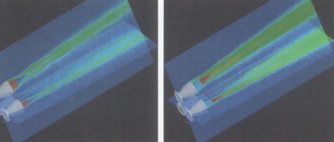
simulations. Figure 6 shows cross sections through the plume flowfield for both power settings. Overset on the Mach number contours in the figure are the locations of the SSME Mach disks visually observed and scaled from test stand imagery. The agreement between the CFD model and experimental Mach disk locations is very encouraging.
Figure 6: Comparison of SSME 3D Reacting Flowfield Simulations against Test Imagery Mach Number Contours Shown
(Symbols Depict Mach Disk Location Scaled from Test Imagery)
Figure 7 shows a side-by-side comparison of the single SSME 3D flowfields generated with the fully reacting internal/external model against the external-only model utilizing the
RAMP-Figure 7: Comparison of SSME 3-D Modeling Approaches (Top: Full Internal/External Reacting Flow Solution Bottom: External-Only Mixing Flow with RAMP-Based Exit Plane BC) Approved for public release; distribution is unlimited.
based exit plane BC together with the reduction of the chemistry modeling to simple mixing of the combustion products pseudo-species. There is very little loss in detail and accuracy resulting from this simplification.
The external-only mixing model with the RAMP-based BC was tested next for the three-SSME cluster in the SSV coordinate system with the engines gimbaled to 100% power Lift-Off settings as shown in Figure8.The computational model contained 17 million grid cells with axial resolution in the one to three inch range. This is the level of resolution we anticipate will be required to capture the plume interaction with the launch pad. The three-engine model was then attached to the full SSV model.
Figure8: Three-SSME Cluster Plume Simulationat 100% Power Lift-off Gimbal Settings;
Left: Mach Number; Right: Temperature
SRBPlume Definition
While the SRB plume does not have the high Mach numbers and complex shock structure as the SSME plume, it has the added complexity of solid particulates. At the time that the Cycle-2 model development began, no particulate models existed in the Loci-CHEM CFD program. Therefore, the decision was made to approximate the SRB plume by retaining only the gaseous components and eliminating the particulates completely. This approximation results in the volume flow rate of the SRB plume being approximated very well due to the small volume fraction of the particulates.
This approximation results in significant error in the mass and momentum content of the SRB plume. However, the purpose of this simulation is primarily to determine the plume
boundaries and entrained flow, and these quantities should be affected less by this approximation than other important quantities such as plume impact pressure and heating rates.
Recently, an Eulerian model has been added to Loci-CHEM which could be used represent the AI203condensed species particulate in the SRB exhaust plumes. Additionally, a
Lagrangian model is under development for eventual application with CHEM. The Eulerian approach for the alumina in the SRB exhaust flow can also be used in the future for adding the sound and ignition overpressure suppression water injection sprays [20,21]. These capabilities are not part of the planned Cycle-2 model, but can be used for specific critical cases as required.
As for the SSME plumes, significant economy was realized by starting the SRB plume calculation at the nozzle exit plane. The same nozzle code, RAMP, was used to simulate the Approved for public release; distribution is unlimited.
SRB nozzle flow. An axi-symmetric Loci-CHEM calculation, again ignoring particulates, was conducted to provide turbulence model boundary conditions at the nozzle exit plane. Pseudo-species plume effluent properties: molecular weight, specific heat, enthalpy, and entropy, as a function of temperature were calculated via the method described in the SSME discussion above.
Comparisons with the JANNAF standard reference plumes are shown in Figure 9. Present Cycle-2 plumes at sea level in still air are compared to the reference standard plumes [18] (SPF solution of the left).
Figure 9. SSME and SRB Plume Predictions: Cycle-2 CFD versus SPF-3 Reference Left: SSME Velocity Magnitude at 100% RPL; Right: SRB Mach Number
Unstructured Grid SSV Model
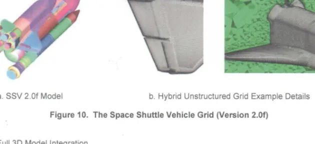
Migration of the Cycle-1 CFD model to the Loci-CHEM unstructured grid format Cycle-2 model required the reconstruction of the existing SSV surface models in unstructured format. The high detail and the traceability of the SSV surface definition to CAD drawings that exists in the existing overset grid model version 2.0f made it desirable to utilize the existing surface definition wherever possible. A procedure was developed to import this SSV surface definition into the Gridgen [22] software package. Figure 10a shows the original overset surface grid model. This surface definition was used as the database onto which the unstruCtured surface grid was constrained. The unstructured grid is comprised of portions of the original OVERFLOW surface grid connected by newly created sections. The surface grids were then applied to generate hybrid viscous volume grids with the AFLR3 grid generator. An example of an unstructured surface and volume grid generated for the Orbiter is shown in Figure 10b.
After assembling the individual models of SSV, MLP, ground and FSS and checking them out individually, the components were combined into the first full 3D LODTA model. The model contains approximately 80 million grid cells with viscous spacing on all surfaces including the ground and uses the Shuttle ground winds model for the atmospheric boundary layer definition.
a. SSV 2.0f Model b. Hybrid Unstructured Grid Example Details
Figure 10. The Space Shuttle Vehicle Grid (Version 2.0f)
Full 3D Model Integration
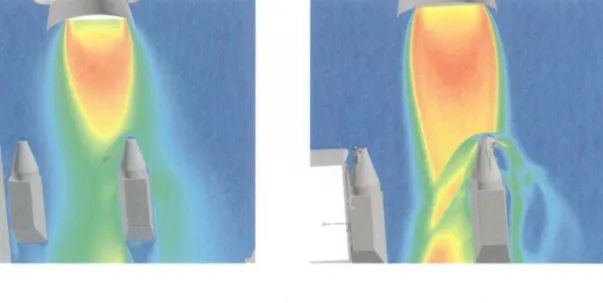
The simulation was run on the Columbia Supercomputer. This first case run was a pre-launch wind only with winds from the West. This case was selected to evaluate the FSS structure wake effects. Figure 30 shows a preliminary flow field calculation. This case is not fully converged and further grid refinements are being made for proper resolution. Nevertheless, the simulation shows the significant wake effects resulting from the presence of the FSS elevator shaft, corner posts, and in particular by the OWP. The solution also shows the considerable influence of the farfield boundary layer approaching from a half-mile away West wind inlet BC.
a. Velocity - in a Vertical Plane b. Velocity - in a Horizontal Plane
Figure 11: Preliminary Flowfield Calculation of Complete SSV on Launch Pad - Pre-Launch
Detailed Single SRB and Symmetric-Half SRB Model Development
As shown in Figure 3, the single and symmetric-half SRB models include all pertinent features within the exhaust hole. The focus of these simulations is on the SRB plume
interactions during the most critical times between approximately1.5 to 4 sec after SRB Ignition. Approved for public release; distribution is unlimited.
This timeframe includes the duration for which the SRBs are over the North holddown posts and haunches. The SRB plumes impinge on the North holddown posts as the vehicle rises and drifts to the North.
Shown in Figure 7 are views of the Left SRB plume impinging on the North outboard SRB holddown post and haunch. Three Cycle-2 views are shown together with the reference Cycle-1 flowfield view. There is a strong plume shock over the blast cover over the holddown post and there is flow turning toward the wall of the exhaust hole above the haunch. There is a blast deflector that overhangs the top of the exhaust hole and scoops away some of the upward plume flow at the wall. This flowfield is in striking contrast to the Cycle-1 flowfield.
a. Cycle-1 Reference b. Cycle-2
Figure 7. Left SRB Plume - MLP Interaction Flowfield
ONGOING WORK
The planned symmetric half-SRB CFD model simulations are completed. They are currently being applied to evaluate the transport potential of critical debris sources. The single SRB model is the next CFD model to be executed. This model will be used primarily to determine effects of geometrical asymmetry in the SRB hole or asymmetry with respect to vehicle position on the development of the dominant flow features in the region. Finally, the Full 3D model will be executed.
SUMMARY AND CONCLUSIONS
The Cycle-2 Shuttle Lift-Off CFD model has been developed. The conceptual model is realized in three constituent computational models ranging from an integrated 3D model which includes key aspects of the launch facility as well as the integrated vehicle to a half-SRB model which provides high resolution of key geometrical details of SRB plume/MLP structure interaction. These computation models involve the integration of propulsion analysis for the nozzle/plume flow with the overall 3D vehicle flowfield at Lift-Off. The Cycle-2 Shuttle Lift-Off models have been implemented in Loci-CHEM with an unstructured grid flow solver, grid refinements, and multi-phase plume flow modeling capability. In addition, a multi-disciplinary approach is being taken to address the rebound of plume driven debris sources from the launch facility and/or the SSV.
Usingthecomputational
modelsdescribedinthispaper,a seriesofsimulations
arebeing
performed
tocovertheparameter
spaceof debrissources,vehicletrajectories
andenvironmental
conditions
atlaunchthatdefinetherisktotheSSVforexpectedLift-Offdebris.Thesimulations
thusproduced
arebeingusedtoevaluatetheplume-induced
debrisenvironment
wherethemulti-plumeinteractions
withthe launchfacilitycanpotentially
accelerate
debrisparticlestowardthe
SSVas plume-driven
debrisor fallingdebrismaybeaccelerated
towardsthevehiclebyplume
aspiration.Thesesimulations
willfurtherbeusedtoquantifytheincremental
increaseinriskfrom
identified
unexpected
debrissourcesforwhichmitigationis incomplete.Inthisway,thedebris
transportanalysescanbeusedtoappropriately
prioritizethemitigation
of potentialdebris
sourcestocontinuetoreducetherisk.
ACKNOWLEDGEMENTS
The contributions of Suzanne Dorney, Alan Droege, Joe Ruf, Josh Wilson, and Jason Mishtawy, NASA/MSFC, Luke Henke, USA/MSFC, and Jerry Radke and Matt Slaby, CFDRC, to this work are gratefully acknowledged.
o 2. . . 5. . . . . REFERENCES
Buning, P. G., et al., OVERFLOW Users Manual, version 2.0s, (April 2003).
Gomez, R.Jo, Vicker, D., Rogers, S.E., Aftosmis, M.J., Chan, W.M., Meakin, R., and Murman, S., STS-107 Investigation Ascent CFD Support, AIAA 2004-2226, (July
2004).
Dougherty, N.S., West, J.S., Droege, A., Wilson, J., Liever, P.A., and Slaby, M., Space
Shuttle and Launch Pad Computational Fluid Dynamics Model for Lift-Off Debris
Transport Analysis, presented at the NASA 17t" Annual Thermal and Fluids Analysis Workshop, College Park, MD, (August 2006).
High-End Computing at NASA, NASA Technical Report NAS-07-001, (January 2007).
Ruf, J., McDaniels, D., Mishtawy, J., Ramachandran, N., and Hammad, K.J., Cold Flow
Nozzle Plume Entrainment Test and Data Overview, AIAA 2006-4413, (July 2006). Stellingwerf, R. F., Robinson, J., Stallworth, R., SPHCAnalysis of Launch PadDebris
Rebounds, Stellingwerf Consulting, Technical Memo 060930, Jacobs ESTS Group Task
Order: 32-030201-00, (October 2006).
Liever, P.A., Slaby, M., and Habchi, S., Development of Cycle-2 Lift-Off Debris Transport Analysis Tool Definition, CFDRC Final Report, Jacobs ESTS Group Task
Order: 23-040301-00, Huntsville, AL, (October 2006).
Luke, E.A., Loci: A Deductive Framework for Graph-Based Algorithms, Third International Symposium on Computing in Object-Oriented Parallel Environments, edited by S. Matsuoka, R. Oldehoeft, and M. Tholburn, No. 1732 in Lecture Notes in Computer Science, Springer-Verlag, pp. 142-153, (December 1999).
Luke, E.A., Tong, X-L., Wu, J., Lin, T., Cinella, P. A Chemically Reacting Flow Solver
for Generalized Grids, AIAA, (2003).
10. 11. 12. 13. 14. 15. 16. 17. 18. 19. 20. 21.
Luke, E.A., Tong, X-L., Wu, J., Lin, T., Cinella, P. CHEM 3: A Finite-Rate Viscous
Chemistry Solver- The User Guide, Mississippi State University, (July 2006).
Gaither, J., Marcum, D., and Mitchell, B., SolidMesh: A Solid Modeling Approach to
Unstructured Grid Generation, 7th International Conference on Numerical Grid
Generation in Computational Field Simulations, (September 2000).
Marcum, D.L., Unstructured Grid Generation Using Automatic Point Insertion and
Local Reconnection, The Handbook of Grid Generation, edited by J.F. Thompson, B.
Soni, and N.P. Weatherill, CRC Press, p. 18-1, (1998).
Marcum, D.L., Advancing-Front/LocaI-Reconnection (AFLR) Unstructured Grid
Generation, Computational Fluid Dynamics Review, World Scientific-Singapore, p. 140,
(1998).
Terrestrial Environment (Climatic) Criteria Handbook for Use in Aerospace Vehicle
Development, NASA Technical Handbook, NASA-HDBK-1001, (August 2000).
Dougherty, N.S., Space Shuttle Lift-Off Computational Fluid Dynamics Model:
SSME Geometry, Jacobs Sverdrup MSFC Group Report MG-06-0274, (July 2006).
Quirk, J., A Contribution to the Great Riemann Debate, ICASE Report 92-64, (1992).
Einfeldt, B., On Godunov-Type Methods for Gas Dynamics, SlAM Journal on
Numerical Analysis, Vol. 25, pp. 294-318, (1988).
Smith, S.B, Unified Test Stand Design and Environmental Impact Model, Final
Report Contract NAS13-01006, (July 2003).
Evans, J.S. and Schexnayder, C.J., Influence of Chemical Kinetics and Unmixedness on Burning in Supersonic Hydrogen Flames, AIAA Journal, Vol. 18 No. 2, pp.
188-193, (January 1980).
Canabal, F., and Frendi, A., Study of the Ignition Overpressure Suppression
Technique by Water Addition, AIAA Journal of Spacecraft and Rockets, Vol. 43, No. 4,
(July-August 2006).
Woo, J., Studies Related to 6.4 % Model Overpressure Assessment, GAMMA Research Report GRI-TP-81-10, Huntsville, AL, (December 1981).
22. Gridgen, Software Package, Version 15, Pointwise, Inc., Bedford, Texas, (2005).
NOMENCLATURE AFLR AIAA BC-CAD CFD CFDRC DOF DTA ERC Advancing-Front/LocaI-Recon nection
American Institute of Aeronautics and Astronautics Boundary Condition
Computer-Aided Design Computational Fluid Dynamics
Computational Fluid Dynamics Research Corporation Degrees of Freedom (3-DOF, 6-DOF)
Debris Transport Analysis
![Figure 1. Pressure Coefficient on the Space Shuttle Launch Vehicle and in the Near-Body Flowfield [4]](https://thumb-us.123doks.com/thumbv2/123dok_us/11062846.2992956/3.918.361.613.111.389/figure-pressure-coefficient-space-shuttle-launch-vehicle-flowfield.webp)