ISSN: 1992-8645 www.jatit.org E-ISSN: 1817-3195
FAST HANDOVER FOR MICROCELL DISCOVERY IN
WIRELESS NETWORKS
1, 2
A. M. Miyim, 1Mahamod Ismail and 1Rosdiadee Nordin 1
University Kebangsaan Malaysia, Department of Elect., Electronics & Systems Engineering, Malaysia
2
Federal University Dutse, Department of Computer Science, Nigeria
E-mail: 1, [email protected], 1{mahamod, adee}@ ukm.edu.my
ABSTRACT
Considered as low-powered cellular base stations, Microcells (Femtocells) are found to be deployed in homes and public places. They provide good coverage for very high user data throughputs and operate on licensed spectrum. This paper propose cell reselection transmit beacon (CRTB) transmitted by microcell on the cellular frequency to aid quick discovery of microcell. The performance of microcell discovery is achieved by setting a proximity threshold for the macrocell high enough to impact on mobile user equipment (UE) in the network. Simulation results demonstrate the effectiveness of the beacon in triggering cell reselection while impacting little on the macrocell UE throughput and facilitate the handover procedure at the microcell base station.
Keywords: Microcell; Beacon; Cell-Edge; Macrocell; Throughput.
1. INTRODUCTION
Femtocell is a term that is generally referred to low-power base station in providing cellular service within airports, residences, schools, and business environments. The mobility of the User Equipment (UE) has inherently made handover procedures to become an integral part of cellular network design. However, a handover procedure is triggered only when a UE roams to a region where the received signal strength (RSS) from its associated macrocell base station ((e)NB) is significantly lower than the signal strength of a new (e)NB. Similarly, when a UE comes into close range with a new (e)NB than its currently associated macrocell base station ((e)NB), handover is ensured (changes its association to the new (e)NB). A handover procedure aims to be fast enough in order to uphold its transparency to the running applications [1].
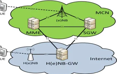
The tiny cells capable of providing high-speed data lie inside larger cells served by nearby macrocell base stations. To operate such an underlay network reliably, microcells need to avoid any interference with macrocells and provide a seamless experience to users as they roam in and out of microcell coverage [2]. The fundamental difference between micro- and macrocell lies in their respective backhauls. While the backhaul of a microcell is an interface to the Mobile Core Network (MCN) through the public internet, that of
[image:1.612.316.520.404.533.2]macrocell backhaul is line dedicated to the MCN as demonstrated in Figure 1.
Figure 1: Topology of a Handover Process
Additional latency is introduced when traditional handover procedure is applied on microcells between Home-enhanced NodeB (H(e)NB) and the MCN in the public internet. More so, due to the small size of microcell, the handover frequency equally increases, thereby making it difficult for a fast moving UE to maintain its connectivity with quick passing microcells in its path. For mobile UEs to take advantage of offloading macrocell traffic to microcells, a faster handover mobility procedure to quickly discover the microcells is required.
ISSN: 1992-8645 www.jatit.org E-ISSN: 1817-3195 topic. Section III introduces the simulation
methodology and assumptions, including the path-loss modelling, dynamic simulation model, and the SIB parameter assumptions. The simulation results on microcell discovery performance as a function of proximity threshold are presented in Section IV. Section V describes cell reselection beacon to in facilitating microcell discovery. The conclusion is given in Section VI.
2. RELATED WORK
As a result of the increasing demands for data and real-time services, wireless networks are compelled to support different traffic characteristics and Quality of Service (QoS) guarantees. After all, current wireless technologies and networks do satisfy different needs and requirements of mobile users as they complement each other in terms of their capabilities and suitability for different applications. The integration of these networks enables mobile users to be always connected to the best available access network depending on their requirements. Efficient handover mechanisms are essential for ensuring seamless connectivity and uninterrupted service delivery. A number of handoff schemes in a heterogeneous networking environment are therefore necessary.
Marquez-Barja, et al [3] have described the concept of being always best connected, the user experience and business relationships in an ABC environment, and outlined the different aspects of an ABC solution that will broaden the technology and business base of next generation communication. Also, an advanced heterogeneous vehicular network (AHVN) architecture, which uses multiple access technologies and multiple radios in a collaborative manner have been outlined in [4].
A general overview of vertical handover decision algorithms are discussed in [5-7], whereas, a new Prefetch-based Fast Handover procedure was proposed in [1], designed to overcome the drawbacks introduced by the usage of the public internet for message paths between femtocell base stations and the mobile core network. The new proposed procedure simplifies and speeds up the handover procedure at the cost of consuming more network resources at the femtocell base station.
The authors in [8] studied the impact of network load of neighbouring cell sectors on the inter-cell interference in a cellular data network.
Their work uses a combination of pilot and traffic load measurements to provide better estimate of the user SINR by taking better account of the contribution of inter-cell interference. The result of which a higher throughput was recorded by users located far from the base station.
Due to asymmetric power of macro and femto BSs in HetNets, some modifications must be done on RSS algorithms which have been mainly proposed for homogeneous networks, to be effectively used in HetNets. Authors in [9] proposed a new RSS based HO algorithm, referred to as RSS-α, for a handover scenario where a user moves from a macrocell to a femtocell. The main idea behind the RSS-α algorithm is to find optimum combination factor that merges the values of RSS from a serving macro BS and the target femto BS to derive a reasonable handover criterion.
Since the procedure to handle handovers
involving femtocells are far from being
standardized, the application of traditional (legacy) handover procedure to such handovers introduces additional latency between the H(e)NB and the MCN in the public internet [10]. While handover between macrocells take less time (<100ms), it takes over 150 ms to transmit a single message over the internet.
While a lot of researches are focusing on microcell networks, the issue of handover between macro- and microcells still receive less attention. However, ideas like proactive triggering handover procedures by predicting mobility of users [11], reducing the scanning time to identify associable femtocells by caching recently visited cell information [12], reducing unnecessary handovers by modifying the architecture and signal flow [13-15], have started to yield some inroad in tackling the problem. There are also some work that focuses on improving handover efficiency in other networks [16].
Traffic offloads from macro cellular networks and cost reduction of infrastructure deployment [1], [17] are assumed to be the key benefits of microcells. One challenge for the microcell deployment is its (microcell) discovery. That is, a UE that originally camps on a macrocell with different frequency and better quality (Ec/Io)
than the microcell arriving the microcell
ISSN: 1992-8645 www.jatit.org E-ISSN: 1817-3195 network needs to be set high so as to impact on all
the UEs in the network. As a solution, a cell reselection transmit beacon (CRTB) is proposed with the microcell transmitting a beacon on the frequency of macrocell. The beacon is to be randomly chosen in the time domain to minimize the interference on the neighbouring mobile nodes.
3. SYSTEM SIMULATION MODELS AND
ASSUMPTIONS
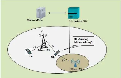
[image:3.612.97.291.403.528.2]One of the challenges for the microcell deployment is its discovery by the UE. This is to say, UE that is originally attached to a macrocell with different frequency and quality (Ec/Io), may not be able to identify and switch to microcell on arriving H(e)NB as illustrated in Figure 2. To facilitate the discovery of the microcell, a broadcast by the macrocell network must be set high so as to impact on any mobile UE in the network. Transmit beacon consist of pilot signal and control channels radiated on macro frequency for microcells (femtocells), to attract sleeping mobile UEs attached to macrocell when microcell forward link (FL) frequency and neighbouring macrocell are operating on different frequencies [18].
Figure 2: Microcell Architecture With UE Camping On
Macrocell.
Based on the introduction of the RF model, the path loss and the corresponding Ec/Io values from macrocells and microcells to a UE are generated at identified location. The path loss for
the macrocell and microcell are PLm and PLf,
respectively and are calculated by the expressions as follows:
PLm = 28 + 35 log10 (d1) dB (1)
PLf = 38.5 + 20 log10 (d2) dB (2)
where d1 and d2 are the distances of the mobile UE
to the macrocell and microcell base stations,
respectively, and the wall partition loss is assumed to be 10 dB.
Due to the abrupt change of the received signal strength from macrocell and microcell BSs, average received signal powers from macrocell and microcell BSs to track the signal power changes at
the mobile terminal is here considered. Let
Π
mand
Π
f denote the average received power at themobile terminal from the macrocell and microcell BSs respectively.
From [12, 14], Πm and Πf can be found as follows:
m
Π
=∑
−
=
Π
10
1
wavi m av
w
(3)f
Π
=∑
−
=
Π
1
0
1
wavi f av
w
(4)where Wav is the window size defined as follows:
wav =
s avVT
d
,
10
max
(5)Ts and dav - denote RSS sampling interval and
averaging distance respectively, while
⋅
is thefloor operation.
The rate at which the received signal strength changes from the macrocell BS can be found from the expression: s s y x m T w S S − =
ℜ (6)
where ws is the window size estimator. The values
of Sx and Sy are given by:
[
]
∑
− = + Π = 1 2 0 1 2 s w i s m s x w w S (7)[
1]
2 1
2
+ Π
= w
∑
− sw m s y w w S s s (8)
3.1 Simulation Model
ISSN: 1992-8645 www.jatit.org E-ISSN: 1817-3195 microcell across the entire network. The path loss
[image:4.612.88.298.161.277.2]profile, generated by the WinProp for micro cell location is shown in Figure 3. The path loss profile of macro depends on the location of the neighbourhood within the macrocell.
Figure 3: Pathloss Profile of Microcell Location
3.2 UE Mobility
[image:4.612.338.515.390.543.2]Three types of neighbourhood mobility routes are used: outdoor, corridor, and in-door. Once more, the primary aim is to model the idle UE movement patterns through the neighbourhood, through buildings, and within offices. The three routes model a UE walking from the entrance of the building, along the corridor and terminating at the entrance of an apartment. The in-door routes start from the entrance of the apartment and proceeds to a resting point (desk, dining table or counter), on which the UE rests. It shows typical behaviour of a mobile user when returned home and places his/her handheld device(s) in a fix location. The other category consists of the UE periodically traversing the building many times within a period of time. This route captures the behaviour of a mobile user whose handheld device(s) moves around the apartment while he/she moves as illustrated in Figure 4.
Figure 4: Indoor Routes of UE’s Movement.
A two-frequency deployment scenario is
assumed: frequency f2 is shared by macro- and
microcells, while f1 is for macrocells only. The two
frequencies are assumed to be adjacent with an adjacent channel interference ratio (ACIR) of 33dB. A microcell is only accessible to its own home UE (HUE) and not accessible to any other HUEs or macro UEs (MUEs). For this analysis, the enhanced Macro NodeBs (M(e)NBs) are then assumed to transmit at 1/2 the full power (i.e., 40dBm). It is also assumed that 1/10th of the full power is allocated to pilot signal for both M(e)NBs and H(e)NBs. Likewise 5-2.5% for micro penetration at cell edge and at cell site respectively.
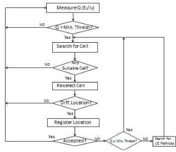
Based on the above deployment assumptions and the path loss profiles generated by our model, one can obtain the Ec/Io of all the (e)NodeBs measured by a UE at any point along the mobility routes. Fading effect is also simulated and added to the path loss. The Ec/Io data are then fed as the simulator input which follows the 3GPP cell reselection procedure given in the 3GPP25.304 [19] and depicted in Figure 5.
Figure 5: Flow Chart of Cell Reselection Procedure.
Table 1 summarises the relevant cell reselection parameters for the broadcast in an idle
mode. The frequency f2 is set as the camping carrier
[image:4.612.91.297.580.699.2]ISSN: 1992-8645 www.jatit.org E-ISSN: 1817-3195
Table 1: SIB Parameters for Idle Cell Reselection
SIB Parameter
Macro f1, f2 Micro f2
Ec/Iomin, SIB3 -15dB -15dB
Max. Threshold
12dB 1.8dB
Min. Threshold
(1.8 – 12)dB 1.8dB
Ec/Iohyst 1.8dB 1.8dB
Ec/Iooffset
Macro f1: 0dB Macro f2: 50dB
Micro f3: -50dB
Macro f1: 0dB Macro f2: 0dB Micro f3: 0dB
Ec/Iomin, SIB11
Macro f1: -15dB Macro f2: -15dB Micro f3: -12dB
Macro f1: -15dB Macro f2: -15dB Micro f3: -15dB
*SIB – System Information Block:
SIB-3 is Parameter for intra-,
inter-frequency and I-RAT cell re-selections.
SIB-11 is the secondary notification.
3.3 Assumptions and Limitations
The two-frequency deployment scenario (f1 is for
macrocells and f2 for femtocells) is assumed with an
adjacent channel interference ratio (ACIR) of 33dB. Although the paper focuses on two-frequency scenario, it should be noted that this could equally be applied to other scenarios with dedicated carrier for the microcells. Assumed restriction on association is observed in this setting (i.e., microcell is only accessible to its home UE (HUE) and not to other HUEs or macro UEs.
The paper falls short in conducting laboratory test to confirm the impact of the proposed CRTB on the data throughput. Field measurements were equally not carried out to compare the measured and
predicted pathloss values from UE to the NodeBs.
4. SIMULATION RESULTS
In this section, we present the simulation results based on the mobility simulation. The UE arriving micro network find it difficult to locate its own microcell on other frequencies, if proximity threshold is low. For good microcell discovery, the proximity threshold needs to be set high enough so that it impacts on all the UEs in the network. Hence, it is desirable to keep proximity threshold low without compromising femtocell discovery performance. To this end, two solutions are proposed. One is through UE enhancements to perform autonomous periodic inter-frequency searches irrespective of the quality of the serving cell. The other is the so-called cell reselection
beacon where the femtocell transmits a beacon on macro frequency(ies) to trigger reselection.
Table 2: Simulation Parameters
Parameter Value
Transmit Power of Macro BS -Tx(m) 43dBm
Transmit Power of Micro BS – Tx(f) 21.5dBm
Shadowing of Macrocell Signal -
m
σ
8dB
Shadowing of Microcell Signal -
f
σ
6dB
RSS Threshold for Macro -
γ
m -90dBmHysteresis Margin -
∆
3dBmWall Loss -
W
10dBRSS Sampling Interval -
T
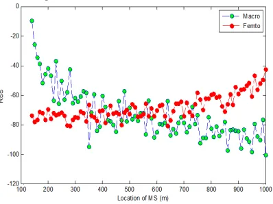
s 0.7sFigure 6 shows the received signal strength from macrocell and femtocell BSs at the mobile station versus the location of the user, when the user is moving towards the microcell BS with a constant velocity. However, variable length of
window size was considered for making
[image:5.612.315.514.413.562.2]appropriate handover decision.
Figure 6: RSS by the UE from Macro and Micro BSs.
4.1 UE Upgrade
One solution that guarantees microcell
ISSN: 1992-8645 www.jatit.org E-ISSN: 1817-3195 search (SBS), the performance of the micro
discovery of the home UE will significantly improve. This method applies only to the approaching UEs that tend to cause setback, but failed to solve the microcell discovery issue of legacy UEs. To ameliorate the bottleneck, a cell reselection transmit beacon is therefore proposed.
4.2 Cell-Reselection
To facilitate microcell discovery without increasing proximity threshold, the microcell transmits a beacon signal on the macrocell’s frequency which reduces the Ec/Io of the macrocell to be lower than proximity threshold. Hence the UE will perform inter-frequency cell search when hit by the beacon even with low proximity threshold (2dB). For most of the time, the microcell transmits a low-power beacon once a while in very short time
interval. The low-power beacon however,
guarantees very fast cell reselection to microcell when the home UE is in close vicinity of the micro network and the high power beacon covers the entire in-door.
By considering an idle-mode UE within the coverage area of a high-power beacon camping on a
strong macro on frequency f1 (figure 2), the UE will
execute inter-frequency search to reselect microcell. However, since the beacon signal is bound to cause interference to nearby MUEs (voice or data calls), the transmit power can be carefully chosen to achieve good microcell discovery and minimize the interference to macro network users.
5. MICROCELL DISCOVERY
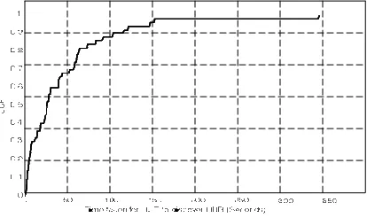
In order to evaluate the performance of the fast handover procedure reflecting on the microcell discovery, the system was simulated to show its flexibility in the implementation of procedure modifications, along with user mobility. The implementation simulates a mobile UE driving at varying average speeds through streets in a specific residential neighbourhood, shown in Figure 3. In the femtocell discovery, the proximity threshold in macrocell’s system information block (SIB) is set to be 1.8dB; the macrocell pathloss is set low to mimic a cell site scenario where the macro quality is very good and no inter-frequency cell search would occur in the absence of the beacon. Therefore, if the femto is found, it will be ranked the highest. Figure 7 shows the CDF of the time taken for UE to reselect to the femto. The time is defined as the duration between the moment when the beacon is turned on and the point when the cell reselection to the femto is complete. The average
[image:6.612.316.523.145.268.2]discovery time is found to be below one minute. The UE on rare occasions will have to wait for about 5 minutes before it reselects to the micro.
Figure 7: Microcell Discovery Performance.
Although the impact seems to be significant, it is limited only to the MUEs within the beacon coverage. If we take all the MUEs in the macrocell into account, the impact would be significantly diluted.
The result of the proposed cell-reselection on data throughput has shown that the impact of the beacon on throughput is about 25% of the UE in the coverage area of the beacon when there is only a single user in the macro cell. The throughput could reduce significantly due to beacon bursts when multiple users are served by the same macrocell [20].
6. CONCLUSION
Mobile users attached to macro BS and approaching microcells should be able to discover
and reselect their desired microcell even when the
microcell(s) is operating on another carrier. In ensuring the discovery of the microcell, proximity threshold of the macro BS is set high so as to have influence on any UEs in the network. While the UE
performs periodic inter-frequency search
ISSN: 1992-8645 www.jatit.org E-ISSN: 1817-3195
ACKNOWLEDGEMENTS
The authors wish to thank UKM for the financial assistance and the Federal University Dutse for the support toward the success of this project.
REFERENCES:
[1] Ayaskant Rath and Shivendra Panwar, “Fast
Handover in Cellular Networks with
Femtocells”, vvvvv, pp. xx-xx.
[2] V. Chandrasekhar, J. Andrews, and A. Gatherer,
“Femtocell Networks: A Survey,”
Communications Magazine, IEEE, vol. 46, no. 9, pp. 59 –67, September 2008.
[3] J. Marquez-Barja, C. T. Catafate, J. C. Cano, P. Manzoni, “An Overview of Vertical Handover Techniques: Algorithms, Protocols and Tools”, Computer Communications 34 (2011):985-997, Elsevier, doi: 10.1016/j.comcom.2010.11.010 [4] Ekram Hossain, Garland Chow, Victor C.M.
Leung, Robert D. McLeod, Jelena Mišic´, Vincent W.S. Wong, Oliver Yang, “Vehicular
Telematics over Heterogeneous Wireless
Networks: A survey”, Computer
Communications 33(2010):775–793, Elsevier;
doi:10.1016/j.comcom.20 09.12.010
109/MWC.2003.1182111
[5] J. Z. Sun, “A review of Vertical Handoff Algorithms for Cross Domain Mobility”, Proceedings of International Conference on Wireless Communications, Networking and Mobile Computing, 21-25 Sept.,2007, Shanghai; DOI: 10.1109/WICOM.2007.782
[6] M. Kassar, B. Kervella, G. Pujolle, “An Overview of Vertical Handover Decision
Strategies in Heterogeneous Wireless
Networks”, Computer Communications
31(2008):2607-2620; Elsevier, doi:
10.1016/j.comcom.2008.01.044
[7] X. Yan, Y. A. Sekerciog˘lu, S. Narayanan, “A
Survey of Vertical Handover Decision
Algorithms in Fourth Generation
Heterogeneous Wireless Networks”, Computer
Networks 54 (2010) 1848-1863; Elsevier, doi: 10.1016/j.comnet.2010.02.006
[8] V. P. Mhatre, C. P. Rosenberg, “Impact of Network Load on Forward Link Inter-cell Interference in Cellular Data Networks”, [9] J. Min Moon, Dong-Ho Cho, “Novel Handoff
Decision Algorithm in Hierarchical Macro-Femto-cell Networks,” Conference Proceedings of IEEE Wireless Communications and Networking (WCNC), pp.1-6, 2010.
[10] K. Dimou, M. Wang, Y. Yang, M. Kazmi, A. Larmo, J. Pettersson, W. Muller, and Y. Timner, “Handover within 3GPP LTE: Design
Principles and Performance,” Proceedings of
IEEE 70th Vehicular Technology Conference (VTC 2009), September 2009, pp. 1–5.
[11] A. Ulvan, R. Bestak, and M. Ulvan, “The Study of Handover Procedure in LTE-based Femtocell
Network,” Proceedings of 3rd Joint IFIP
Wireless and Mobile Networking Conference (WMNC), October 2010, pp. 1–6.
[12] H.-Y. Lee and Y.-B. Lin, “A Cache Scheme for Femtocell Reselection,” IEEE Communications Letters, 2010, 14(1):27–29.
[13] M. Chowdhury, W. Ryu, E. Rhee, and Y. M. Jang, “Handover between Macrocell and Femtocell for UMTS based Networks,” Proceedings of the 11th International Conference on Advanced Communication Technology (ICACT), February 2009, pp. 237– 241.
[14] J.-S. Kim and T.-J. Lee, “Handover in UMTS Networks with Hybrid Access Femtocells,” Proceedings of the 12th International Conference on Advanced Communication Technology (ICACT), February 2010, pp. 904– 908.
[15] W. Lee, E. Kim, J. Kim, I. Lee, C. Lee, “Movement Aware Vertical Handoff of WLAN and Mobile Wi-Max for Seamless Ubiquitous
Access”, IEEE Transactions on Consumer
Electronics,2007,53(4):xx-xx;DOI: 0.1109/TCE.2007.4429211.
[16] S. Ray, K. Pawlikowski, and H. Sirisena, “Handover in Mobile WiMAX Networks: The
State of Art and Research Issues”, IEEE
Tutorials on Communications Surveys, 2010, 12(3):376–399.
[17] F. Meshkati, Y. Jiang, L. Grokop, S. Nagaraja, M. Yavuz, and S.Nanda, “Mobility and Capacity Offload for 3G UMTS Femtocells”, Proceedings of Globecom, Dec. 2009.
[18] S. NakWoon, P. Ngoc-Thai, Y. Hyunsoo,
L.Sookjin, H. WonJoo, “Base Station
Association Schemes to reduce Unnecessary Handovers using Location Awareness in
Femtocell Networks,” Springer Wireless
Network, 2013, 19(5):741-753.
ISSN: 1992-8645 www.jatit.org E-ISSN: 1817-3195 [20] M. Yavuz, F. Meshkati, S. Nanda, A.
Pokhariyal, Nick Johnson, B. Raghothaman, and A. Richardson, “Interference Management and Performance Analysis of UMTS/HSPA+
Femtocells,” IEEE Comm. Magazine, vol. 47,