ORIGINAL RESEARCH ARTICLE
MODELING OF A WIND TURBINE DRIVEN DFIG USING VARIABLE VOLTAGE AND VARIABLE
FREQUENCY CONTROL FOR REACTIVE POWER COMPENSATION UNDER GRID FAULT
*
Manoranjan Soora and Srinivas Karatlapelly
Asst. Prof, Department of Electrical Engineering, WITS, India
ARTICLE INFO ABSTRACT
This paper deals with the issue of the reactive power compensation in micro grid (MG) by changing the voltage based on Wind Turbine Generator driving a Doubly-Fed Induction Generator (DFIG).Wind generators such as the majority of Distributed Generation(DG) systems are sensitive to the disturbances of the voltage. Under voltage dip (sag) conditions, the induced rotor over currents of the doubly fed induction generators (DFIG) may greatly destroy the converter switches.These systems must to bedisconnected in case of voltage sag, typically where the voltage isless than 80% of rated value. DG which contributes to reduceenergy loss during transmission can increase the capability ofthe voltage control in the power system by generating thereactive power support. In this strategy we proposes to use two separate current control loops on the Machine Side Converter to supply additional active power during system frequency distortions and to reduce the transients in stator voltage after clearing the system voltage dips. In so far we have proposed the design of a current controller on the Grid Side Converter (GSC) to bring the system voltage level to the desired level during the system voltage sag condition. Then, theperformances of both active and reactive power control of the DFIG under grid faults are analyse through Matlab/Simulinksoftware.
Copyright ©2017,Manoranjan Soora and Srinivas Karatlapelly. This is an open access article distributed under the Creative Commons Attribution License, which permits unrestricted use, distribution, and reproduction in any medium, provided the original work is properly cited.
INTRODUCTION
As the demands of industrial needs varying the more outputs of the precise control of our basic electrical prime movers i.e. motor. As compared to AC motors the DC motors are easy to control but with increase in capacity they have their own limitations. Conversely AC motors particularly the Squirrel Cage induction motors are more economical but the speed control of these motor are quiet difficult because alteration of supply frequency is require. Nowadays with technological advancement in drives system, the control of AC motors is more economically, easy to use and the control the range of speed both below and above the base speed. According to the requirement, these drives can fundamentally alter the voltage and the frequency which is being fed to the motor using the technique called Pulse Width Modulation (PWM). Because of user friendly feature and reasonable cost these devices are gaining more popularity.
*Corresponding author: Manoranjan Soora,
Asst. Prof, Department of Electrical Engineering, WITS, India.
As the Variable Frequency Device use the embedded system they can be programmed for automatic control reducing the manual intervention and interfaced to the computer. In the field of HVAC application the usage of Variable Frequency Drive have gained its number. Air handler, chiller, pumps and tower fans are the common application of VFD. A better understanding of Variable Frequency Drives with leads to improve in usage and determining of some appliances and High Voltage AC systems. A basic knowledge of operations, its terms, energy savings, and about the power factors is main aim of this dissertation also Harmonics mitigation by VFD and a simulation project to show how VFD is beneficial for energy savings. In addition to this paper will discuss the comparison between Variable Frequency Drives and other technologies with respect to industrial standards. The Variable Frequency Drive comprises the parts - a input Rectifier unit, a inverter unit and a DC bus. The supply voltage is firstly pass through a rectifier unit where in gets converted into AC to DC supply, the three phase supply is fed with three phase full wave diode where it gets converts into DC supply.
ISSN: 2230-9926
International Journal of Development Research
Vol. 07, Issue, 12, pp.17680-17685, December,2017
Article History:
Received 09th September, 2017 Received in revised form 24th October, 2017
Accepted 19th November, 2017 Published online 29th December, 2017
Key Words:
WECS,DIFG, Reactive Power, Micro Grid, Converters, Crowbar Circuit.
Citation: Manoranjan Soora and Srinivas Karatlapelly 2017. “Modeling of a wind turbine driven dfig using variable voltage and variable frequency
control for reactive power compensation under grid fault”, International Journal of Development Research, 7, (12), 17680-17685.
The DC bus comprises with a filter section where the harmonics generated during the AC to DC conversion are filtered out. The last section consists of a inverter section which comprises with six IGBT (Insulated Gate Bipolar Transistor) where the filtered DC supply is being converted to quasi sinusoidal wave of AC supply which is supply to the induction motor connected to it. In a basic DC-link variable frequency motor controller, the input AC power is converted to DC, filtered and then converted to variable frequency DC by an inverter. A set of SCR switches are used to convert the DC to three phase AC power to drive induction motor. Bypass diodes are needed for reactive power flow and to clamp the voltage to that of DC supply. The filter supplies a DC voltage to the inverter that is largely independent of load current due to filter capacitor. The inverter tends to keep the current constant. The AC to DC converter output may be fixed or variable (voltage or current) depending on the type of inverter and the filter used.
Fig 1. Mechanical capacity control
Variable speed operation of wind turbine is usually used to provide energy with better efficiency. Wind Energy Conversion System (WECS) driven a Doubly-fed Induction Generator (DFIG) has many advantages. Variable speed operation, active and reactive power independent control and lower converter cost. It reduces stress on the mechanical structure and acoustic noise. A modified current control loop on the machine side converter has been proposed to support system frequency control the transients in stator voltage bring the grid voltage. The DFIG is largely used in wind energy systems, and due to the increasing penetration of wind power, developing suitable control strategies and models for DFIG. In fact, analyzing the behaviour of DFIG-based wind turbines under disturbances become more essential. To limit both rotor fault current and DC-link overvoltage within their tolerable ranges during the grid voltage dip, more investigation of the LVRT ability of the DFIG has been achieved. In fact, by increasing the LVRT capacity, the DFIG remains connected to the grid during and after clearing the fault, and then contribute to the power system stability.
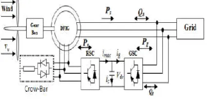
Fig 2. Structure of a WTG driven a DFIG
LVRT needs code requirements in grid code, which is different from country to another. Indeed, for each power system, there are a specific characteristics and protection requirement. When the fault occurs, the wind generator speed up since the mechanical power is much higher than the electrical power provided to the grid.
If the wind turbine is connected to the weak grid, such as a micro grid (MG) for remote applications, the wind generator consumes reactive power. As a consequence, there is more instability of grid voltage and rotor speed. The solutions which are reported in the literature with the concern of grid fault (LVRT and HVRT) can be classified in three categories. (1) Using an active crow-bar at the terminals of Generator Side Converter (GSC), (2) the second category consists of the addition of the converter or dynamic resistor in the DFIG structure and the last class proposes to modify the conventional control scheme of the power converter. The crow-bar is the most solution used in the case of the grid fault where its effectiveness is proven in symmetrical grid unbalance. However, in case of asymmetrical sags such as phase-to-phase faults, crow-bar cannot assist DFIG due to the large negative-sequence of the rotor current. The second solution provides a good result under different grid faults but it has a drawback to increase the overall cost of the wind turbine. The aim of this paper is to give a new approach to control the magnitude of stator voltage. This method permits to provide the set point of the stator reactive power which depends on the stator voltage measurement. Then, conventional vector control of a the GSC is applied in order to achieve the independent active and reactive powers control. The impact of both low and High Voltage Ride through (HVRT) on the active power control performance is addressed. Shunt APF filters are used between the load and DFIG to reduce the harmonics which are produced by the non liner loads and also control the active and reactive power with in the limits to maintain system in stable condition, and hence the power quality is improved and the power factor can also be improved. in order to achieve the independent active and reactive powers control.
Modelling of DFIG Wind Turbine
The DFIG is a wound rotor induction machine which is connected to the grid through both stator and rotor terminals. The stator is directly connected to the grid, while the rotor is connected via a PWM back-to-back converter, which consists of GSC and LSC the rotating mass is decoupled from the system through the converters, an additional control loop is necessary to be added to the DFIG system so as to utilize the kinetic energy of the wind energy conversion system to mitigate the frequency fluctuations of the system.
The kinetic energy stored in the rotating mass of the WECS can be approximately represented by.
n
k
J
E
22
1
(1)
A. Modelling of the Wind Turbine
The mechanical power Pm captured by the turbine from the wind for a given wind speed vw is given by
w p
m
C
v
P
3)
,
(
2
1
(2)
[image:2.595.59.273.611.713.2]The tip speed ratio is given by W r
V
R
(3)Where Ωr represents the rotational speed of the wind turbine in
rad/sec. The mathematical expression of the power coefficient
used in this paper for a wind turbine is given by
) 2 ( 00394 . 0 3 . 0 15 ) 3 ( sin 398 .
0
p C (4)
If the wind speed is below the rated value, the WTG operates in the variable speed mode, and Cp is kept at its maximum value. In this operating mode, the pitch control is deactivated. When the wind speed is above the rated value, the pitch control is activated, in the aim to reduce the generated mechanical power.
Modelling of DFIG
Application of Concordia and Park’s transformations to the three-phase model of the DFIG allows writing the dynamic voltages and fluxes equations in an arbitrary d-q reference frame.
dr r qr qr r qr qr r dr dr r dr ds s qs qs s qs qs s ds ds s dsdt
d
i
r
v
dt
d
i
r
v
dt
d
i
r
v
dt
d
i
r
v
(5)Where rs and rr are respectively the resistance of the stator and rotor windings, ωr and ωs are respectively the rotor reference frame and the rotational speed of the synchronous reference frame.
The flux linkages are given by
qr qs s qr ds dr r dr qr qs s qs dr ds s dsi
M
i
L
i
M
i
L
i
M
i
L
i
M
i
L
(6)Where Ls, and Lr are respectively the inductances of the stator and rotor windings, and M are the mutual inductance. The electromagnetic torque of the DFIG can be expressed as follow:
ds qs qs ds
em
P
i
i
T
(7)
Where P is the number of pole pairs
resistances, the active and reactive stator power can be expressed as
qs ds ds qs s qs qs ds ds si
v
i
v
Q
i
v
i
v
P
2
3
2
3
(8)Doubly-fed induction generator (DFIG) has become the most widely applied wind turbine in variable speed constant frequency (VSCF) wind power generation, since it presents many advantages such as variable speed running, the decoupled control of active and reactive power, and the small rotate difference power. Targeting the doubly-fed wind power system, this paper establishes the overall mathematical model composed of wind turbine, drive system, double-fed induction generator, stator flux orientation vector control tactics, maximum power point tracking tactics.
Reactive Power Management Strategy
The independent vector control of both active power and the reactive power is accomplished through a rotor currents control . In this work, PI controllers are used to control the rotor currents (inner loop) and control both active power and reactive power (outer loop). In order to achieve the decoupling of power control, vector control is adopted, with an appropriate stator field orientation. Hence, the active power and reactive power are proportional to the rotor currents. The ultimate objective of the primary controller in this case is to regulate the output active/reactive power of the VSC at certain references. This strategy assumes the micro grid is formed by another unit or units, i.e. the voltage and frequency at the Point of Common Coupling (PCC) are regulated. In the case of dispatch able (controllable) energy sources, such as fuel cells and micro turbines, the power set points are provided in general by a supervisory control. On the other hand, in the non-dispatch able DER units, such as renewable energy based DER, the power set point is implicitly generated based on the amount of power available at the DC-link of the VSC. The PQ control strategy is commonly implemented using current-mode control, due to the advantages of its inherent fault/overload current protection and superior dynamic performance Nevertheless; voltage-mode control is used as well in grid connected applications.
Fig.3. whole scheme of vector control of the RSC
characteristics of the primary source and the desired role of that source in the islanded micro grid. The independent vector control of both active power and the reactive power is accomplished through a rotor currents control. In this work, PI controllers are used to control the rotor currents (inner loop) and control both active power and reactive power (outer loop). A comprehensive treatment of the virtual impedance concept to mitigate errors in reactive power sharing is presented in The focus has been on the mismatch in the output impedances of the closed-loop controlled inverters that are used to interface the DG units. With proper design of the voltage controller, the closed-loop output impedances must be negligible at steady state around the nominal operating frequency. Therefore, the virtual impedance is dominant, which results in accurate reactive power sharing. However, the analysis in did not consider the mismatch in the physical impedance of the feeders, including transformers, cables, and the interface inductors associated with each unit.
Simulation Results
Case I: Low voltage ride through
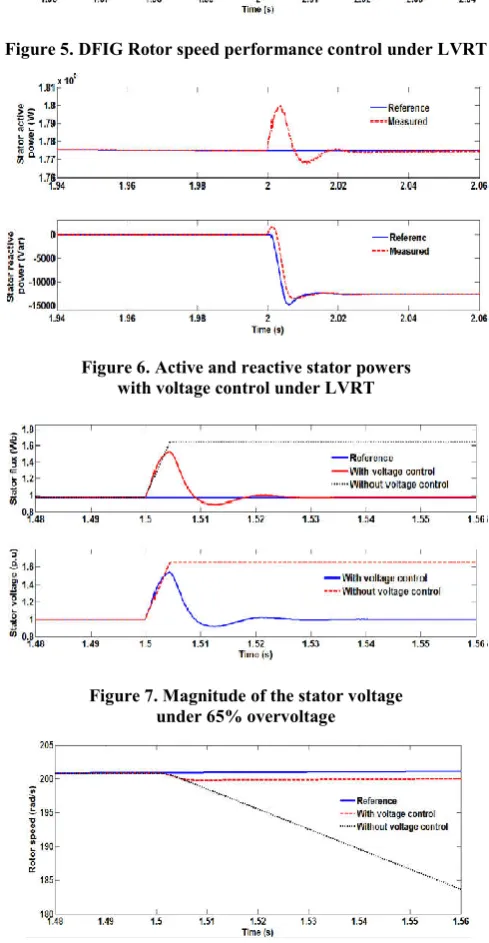
[image:4.595.318.553.46.159.2]In this case, the performance of the control strategy is analyzed where the magnitude of the stator voltage is suddenly reduced by 60% at t = 2 s. For both stator flux and voltage, with our voltage control strategy, the measured values reach the reference value after less than 0.01 seconds unlike the case without voltage control. The performance control of the rotor speed under a sudden decrease of the stator voltage is depicted in Figure 5. The proposed voltage control permits a good tracking of the reference speed. Unlike the case without voltage control, where the speed increase rapidly due to the decreasing of electromagnetic torque. The control of both active and reactive stator powers is depicted in Figure 6. As we can see, the control strategy provides good results. Indeed, with an appropriate reactive power management, a good performance of the active power control is reached, where the wind turbine continue to provide power even under a disturbance. In Figure 6, we can see also that a measured reactive power track with a good performance the reference value provided by the voltage control strategy.
Figure 4. Stator flux and voltage performance comparison
Case II : High voltage ride through
The performance of the control strategy is analyzed where the magnitude of the stator voltage is suddenly increased by 65% at t = 1.5 s. Figure 7 illustrates the performance of the voltage control strategy for both stator flux and voltage.The voltage reaches the reference value after 0.01 seconds with the proposed voltage control strategy. Figure 8 shows the performance of the rotor speed control under increasing of the stator voltage magnitude by 65%.
[image:4.595.310.555.151.623.2]Figure 5. DFIG Rotor speed performance control under LVRT
Figure 6. Active and reactive stator powers with voltage control under LVRT
[image:4.595.47.281.536.665.2]Figure 7. Magnitude of the stator voltage under 65% overvoltage
Figure 8. DFIG Rotor speed control performance under HVRT
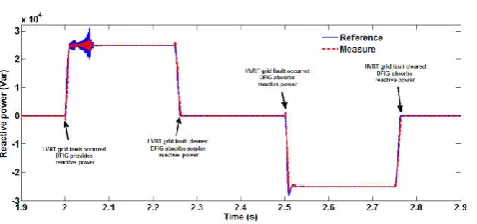
[image:4.595.320.546.643.772.2]Fig 10. Reactive power control performance
With the enhanced control strategy, based on the suitable reactive power management, of grid fault (LVRT,HVRT) on the wind turbine is reduced by using converters and filters.
Conclusion
This paper deals with the troubles which may happen during grid fault such as LVRT and HVRT with doubly fed induction generator which are addressed and an appropriate control strategy for the generator side converter was discussed. In case of the LVRT, a grid voltage decrease may lead to the fast increase of rotor speed due to the decreasing of the electromagnetic torque. Therefore, the wind turbine generator will accelerate due to the unbalance between mechanical torque and an electromagnetic torque. and Dc chopper is used to reduce the losses to increase the stability of the system and to minimize the torque PWM technique with shunt APF is used.
REFERENCES
Xiangjun, L., Dong, H., Xiaokang, L. and Minggao, O. 2010. "Control strategy of wind power output by pitch angle control using fuzzy logic," in Industrial Electronics (ISIE),
2010 IEEE International Symposium on, , pp. 120-124.
Dincer, F. 2011."The analysis on wind energy electricity generation status, potential and policies in the world,"
Renewable and sustainable energy reviews, vol. 15, pp.
5135-5142.
Pena, R., Cardenas, R., Proboste, J., Clare, J. and Asher, G. 2008. "WindDiesel Generation Using Doubly Fed Induction Machines," Energy Conversion, IEEE
Transactions on, vol. 23, pp. 202-214.
Rahimi, M. 2014. "Dynamic performance assessment of DFIG-based wind turbines: A review," Renewable and
Sustainable Energy Reviews, vol. 37, pp. 852-866.
Ganti, V. C., Singh, B., Aggarwal, S. K. and Kandpal, T. C. 2012. "DFIG-based wind power conversion with grid power leveling for reduced gusts," Sustainable Energy,
IEEE Transactions on, vol. 3, pp. 12-20.
Burton, T., Jenkins, N., Sharpe, D. and Bossanyi, E. 2011.
Wind energy handbook: John Wiley & Sons.
Mohd Zin, A. A. B., Pesaran, M. HA, A. B. Khairuddin, L. Jahanshaloo, and Shariati, O. 2013. "An overview on doubly fed induction generators′ controls and contributions to wind based electricity generation," Renewable and
Sustainable Energy Reviews, vol. 27, pp. 692-708.
Raja Singh, R., Raj Chelliah, T. and Agarwal, P. 2014. "Power electronics in hydro electric energy systems–A review,"
Renewable and Sustainable Energy Reviews, vol. 32, pp.
944-959.
Jing, S., Yuejin, T., Yajun, X., Li, R. and Jingdong, L.2011. "SMES Based Excitation System for Doubly-Fed Induction
Superconductivity, IEEE Transactions on, vol. 21, pp.
1105-1108.
Liserre, M., Cardenas, R., Molinas, M. and Rodriguez, J. 2011. "Overview of multi-MW wind turbines and wind parks," Industrial Electronics, IEEE Transactions on, vol. 58, pp. 1081-1095.
Belmokhtar, K., Doumbia, M. and Agbossou, K. 2014. "Novel fuzzy logic based sensorless maximum power point tracking strategy for wind turbine systems driven DFIG (doubly-fed induction generator)," nergy.
Mohanty, A., Viswavandya, M., Ray, P. K. and Patra, S. 2014. "Stability analysis and reactive power compensation issue in a microgrid with a DFIG based WECS,"
International Journal of Electrical Power and Energy
Systems, vol. 62, pp. 753-762.
Attya, A. and Hartkopf, T. 2012. "Penetration impact of wind farms equipped with frequency variations ride through algorithm onpower system frequency response,"
International Journal of Electrical Power & Energy
Systems, vol. 40, pp. 94-103.
Jain, A. K. and Ranganathan, V. 2008. "Wound rotor induction generator with sensorless control and integrated active filter for feeding nonlinear loads in a stand-alone grid,"
Industrial Electronics, IEEE Transactions on, vol. 55, pp.
218-228, 2008.
Iwanski, G. and Koczara, W. 2007. "Sensorless direct voltage control of the stand-alone slip-ring induction generator,"
Industrial Electronics, IEEE Transactions on, vol. 54, pp.
1237-1239.
Shukla, R. D. and Tripathi, R. K. 2014. "A novel voltage and frequency controller for standalone DFIG based Wind Energy ConversionSystem," Renewable and Sustainable
Energy Reviews, vol. 37, pp. 69-89.
Marcetic, D. P. and Vukosavic, S. N. 2007. "Speed-sensorless AC drives with the rotor time constant parameter update,"
Industrial Electronics, IEEE Transactions on, vol. 54, pp.
2618-2625.
Comanescu, M. and Xu, L. 2006."Sliding-mode MRAS speed estimators for sensorless vector control of induction machine," Industrial Electronics, IEEE Transactions on,
vol. 53, pp. 146-153.
Cardenas, R., Pena, R., Proboste, J., Asher, G. and Clare, J. 2005. "MRAS observer for sensorless control of standalone doubly fed induction generators," Energy Conversion,
IEEE Transactions on, vol. 20, pp.710-718.
Forchetti, D. G., Garcia, G. O. and Valla, M. I. 2009. "Adaptive observer for sensorless control of stand-alone doubly fed induction generator," Industrial Electronics,
IEEE Transactions on, vol. 56, pp. 4174-4180.
Rahimi M. and Parniani, M. 2010. "Grid-fault ride-through analysis and control of wind turbines with doubly fed induction generators," Electric Power Systems Research,
vol. 80, pp. 184-195.
Rahimi, M. and Parniani, M. 2014. "Low voltage ride-through capability improvement of DFIG-based wind turbines under unbalanced voltage dips," International Journal of
Electrical Power & Energy Systems, vol. 60, pp. 82-95.
Mohseni, M. and Islam, S. M. 2012. "Transient control of DFIG-based wind power plants in compliance with the Australian grid code," Power Electronics, IEEE
Transactions on, vol. 27, pp. 2813- 2824.
technology and a case for global standard," Renewable and
Sustainable Energy Reviews,vol. 16, pp. 3876-3890.
Awad, A. S., El Rahman, M. A. and Badr, M. A. E. L. "Low Voltage Ride Through Characterization of Single Wind Turbines."
On, E. 2003. "Grid code high and extra high voltage," ON Netz
GmbH, Bayreuth, Germany.
Tsili, M. and Papathanassiou, S. 2009. "A review of grid code technical requirements for wind farms," IET Renewable
Power Generation, vol. 3, pp. 308-332.
Feltes, C., Engelhardt, S., Kretschmann, J., Fortmann, J., Koch, F. and Erlich, I. 2008. "High voltage ride-through of DFIG-based wind turbines," in Power and Energy Society General MeetingConversion and Delivery of Electrical
Energy in the 21st Century, 2008 IEEE, pp. 1-8.
Singh, B. and Singh, S. 2009. "Wind power interconnection into the power system: a review of grid code requirements," The Electricity Journal, vol. 22, pp. 54-63. Sun, T., Chen, Z. and Blaabjerg, F. 2005. "Transient stability
of DFIG wind turbines at an external short-circuit fault,"
Wind Energy, vol. 8, pp. 345-360.
Meegahapola, L. G., Littler, T. and Flynn, D. 2010. "Decoupled-DFIG fault ride-through strategy for enhanced stability performance during grid faults," Sustainable
Energy, IEEE Transactions on, vol. 1, pp. 152-162.
Zhou, Y., Bauer, P., Ferreira, J. A. and Pierik, J. 2009. "Operation of grid-connected DFIG under unbalanced grid voltage condition," Energy Conversion, IEEE Transactions on, vol. 24, pp. 240-246.
Geng, H., Liu, C. and Yang, G.2013. "LVRT capability of DFIG-based WECS under asymmetrical grid fault condition," Industrial Electronics, IEEE Transactions on,
vol. 60, pp. 2495-2509.
da Costa, J. P., Pinheiro, H., Degner, T. and Arnold, G. 2011. "Robust controller for DFIGs of grid-connected wind turbines," Industrial Electronics, IEEE Transactions on,
vol. 58, pp. 4023-4038.
Mehta, B., Bhatt, P. and Pandya, V. 2014."Small signal stability analysis of power systems with DFIG based wind power penetration," International Journal of Electrical
Power & Energy Systems, vol. 58, pp. 64-74.
Domínguez-García, J. L., Gomis-Bellmunt, O., Bianchi, F. D. and Sumper, A. "Power oscillation damping supported by wind power: A review," Renewable and Sustainable Energy Reviews
Mohseni, M., Masoum, M. A. and Islam, S. M. 2011. "Low and high voltage ride-through of DFIG wind turbines using hybrid current controlled converters," Electric Power
Systems Research, vol. 81, pp. 1456-1465.
Morren, J. and De Haan, S. W. 2005. "Ridethrough of wind turbines with doubly-fed induction generator during a voltage dip," Energy conversion, ieee transactions on, vol. 20, pp. 435-441.
López, J., Gubía, E., Olea, E., Ruiz, J. and Marroyo, L. 2009. "Ride through of wind turbines with doubly fed induction generator under symmetrical voltage dips," Industrial
Electronics, IEEE Transactions on, vol. 56, pp. 4246-4254.
Xiang, D., Ran, L., Tavner, P. J.and Yang, S. 2006. "Control of a doubly fed induction generator in a wind turbine during grid fault ridethrough," Energy Conversion, IEEE
Transactions on, vol. 21, pp. 652-662.
Xu, L. 2008. "Coordinated control of DFIG's rotor and grid side converters during network unbalance," Power
Electronics, IEEE Transactions on, vol. 23, pp. 1041-1049.
Gomis-Bellmunt, O., Junyent-Ferre, A., Sumper, A. and Bergas- Jan, J. 2008. "Ride-through control of a doubly fed induction generator under unbalanced voltage sags,"
Energy conversion IEEETransactions on, vol. 23, pp.
1036-1045.
Hu, J., He, Y., and Xu, L.2010."Improved rotor current control of wind turbine driven doubly-fed induction generators during network voltage unbalance," Electric Power
Systems Research, vol. 80, pp. 847-856.
Poddar, G. and Ranganathan, V. 2006. "Sensorless double-inverter-fed wound-rotor induction-Machine drive,"
Industrial Electronics, IEEE Transactions on, vol. 53, pp.
86-95.
Hopfensperger, B., Atkinson, D. and Lakin, R. 2000. "Stator-fluxoriented control of a doubly-fed induction machine with and without position encoder," in Electric Power
Applications, IEE Proceedings-, pp. 241-250.
Iwanski, G. and Koczara, W. 2008. "DFIG-based power generation system with UPS function for variable-speed applications," Industrial Electronics, IEEE Transactions on, vol. 55, pp. 3047-3054.
Munteanu, I., Bratcu, A. I., Cutululis, N. A. and Ceanga, E. 2008. Optimal control of wind energy systems: towards a
global approach: Springer.
Miller, N.W., Price, W. W. and Sanchez-Gasca, J. J. 2003. "Dynamic modeling of GE 1.5 and 3.6 wind turbine-generators," GE-Power systems energy consulting.