http://dx.doi.org/10.4236/opj.2016.68B031
How to cite this paper: Zhou, Y., Shao, Y.F., Wang, Z.F., Li, C.X., Zhou, J.Y. and Ma, W.Z. (2016) Research on Dispersion Compensation of 40 GB/s Optical Duo-Binary Coded Transmission System. Optics and Photonics Journal, 6, 190-195. http://dx.doi.org/10.4236/opj.2016.68B031
Research on Dispersion Compensation
of 40 GB/s Optical Duo-Binary Coded
Transmission System
Yue Zhou, Yufeng Shao
*, Zhifeng Wang
*, Changxiang Li, Junyi Zhou, Wenzhe Ma
Faculty of Engineering, Shanghai Polytechnic University, Shanghai, China
Received 1 July 2016; accepted 18 August 2016; published 25 August 2016
Abstract
A 40 Gb/s high speed optical transmission system is designed, and the different dispersion com-pensation schemes are adopted to realize the transmission of the optical duo-binary (ODB) signals over 120 km optical fiber. Optical duo-binary signals are generated by using a precoder, two low- pass filters (LPF) and one mach-zehnder modulator (MZM). Through combination of dispersion compensation fiber (DCF) and single mode fiber (SMF) in the transmission link, four different dis-persion compensation schemes (pre-compensation, post-compensation and hybrid compensation (pre+ post) and hybrid compensation (post+ pre)) were compared. Analyzing Q factor, BER, eye diagrams and receiver sensitivity in several dispersion compensation schemes, the simulation results are: the cut-off frequency of LPF affects the transmission performance, and the hybrid compensation (post+ pre) scheme is the optimal dispersion compensation method.
Keywords
Optical Communication, Duo-Binary, Dispersion Compensation, Q Factor, Eye Diagrams
1. Introduction
The two development directions of optical fiber transmission system are high speed and long span, and the at-tenuation and dispersion have effects on optical signals transmission [1]. Especially, the dispersion of SMF has reached 16 PS/nm·km, the distance of 40 Gbit/s signal can only be transmitted to 4 km without using dispersion compensation techniques [2]. Nowadays, the optical dispersion compensation methods mainly included: disper-sion compensation fiber (DCF), fiber Bragg grating (FBG), virtually imaged phased array and planar waveguide technology [3]. DCF technology has been widely used since it has large compensation bandwidth, technology maturity and stable performance [4]. At the same time, in order to increase the dispersion tolerance, extend the repeating distance and improve the spectrum efficiency, the optical duo-binary (ODB) coding has been used. ODB modulation format has some advantages like high dispersion tolerance, high spectrum efficiency and high anti-nonlinear ability in high-speed optical fiber communication system. The ODB signal has also better
mission capability for its spatial response characteristic according to the Nyquist’s second criterion [5] [6]. In this paper, optical duo-binary signals are generated using low pass filter (LPF-ODB) is proposed. In order to compensating dispersion, four kinds of dispersion compensation schemes are designed and compared.
2. Principle of Dispersion Compensation
The dispersion of SMF in the 1550nmwavelength is 17 - 20 ps with positive dispersion slope. In order to achieve high speed, large capacity and long distance communication, it is necessary to use DCF in the optical fiber [7], thus the total dispersion of the whole optical fiber line is approximately zero [8]. Compared to the SMF, DCF has larger attenuation. It is necessary to add the amplifier like EDFA to compensate in the system [9]. Ac-cording to the flexible permutation and combination of DCF, SMF and EDFA, four kinds of compensation schemes are used to design simulation model. As shown in Figures 1(a)-(d) respectively, pre-compensation and post-compensation, hybrid compensation (pre+ post) and hybrid compensation (post+ pre). The compensation method of simulation is symmetrical compensation, and the dispersion and dispersion slope of SMF can be compensated by DCF completely. The gain of EDFA after the SMF and DCF is 5dB and 10dB respectively, just might compensate to the attenuation of SMF and DCF. Parameters of the optical fiber are shown in Table 1.
3. Results
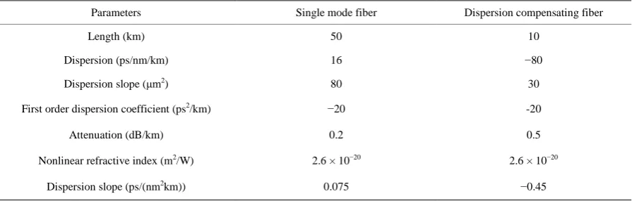
In this paper, Optisystem 13 is used to simulate a rate of 40 GB/s dispersion compensation fiber optical trans-mission system. The system diagram is shown in Figure 2.
[image:2.595.129.498.374.524.2]First of all, according to Figure 2, TX is consist of continuous wave (CW) laser, MZM, pseudo random se-quence generator, non-return to zero(NRZ) pulse generator, binary pre coder and low-pass filter (LPF). The output wavelength of CW laser is 1550 nm, the power is 3 dBm and line width is 0.1 MHz. The extinction ratio
Figure 1. Dispersion compensation schemes (a) Pre-compensation (b) Post-compensation (c) Hybrid-compensation (Pre + Post) (d) Hybrid-compensation (Post+ Pre).
Table 1. Parameters of optical fiber link.
Parameters Single mode fiber Dispersion compensating fiber
Length (km) 50 10
Dispersion (ps/nm/km) 16 −80
Dispersion slope (μm2) 80 30
First order dispersion coefficient (ps2/km) −20 -20
Attenuation (dB/km) 0.2 0.5
Nonlinear refractive index (m2/W) 2.6 × 10⁻²⁰ 2.6 × 10⁻²⁰
Dispersion slope (ps/(nm2km)) 0.075 −0.45
TX RX SMF DCF 10km 50km DCF 10km SMF 50km
EDFA DCF EDFA EDFA EDFA
SMF 50km 10km SMF 50km DCF 10km
EDFA EDFA EDFA EDFA
SMF DCF 10km 50km SMF 50km DCF 10km
EDFA EDFA EDFA EDFA
DCF SMF 50km 10km DCF 10km SMF 50km
EDFA EDFA EDFA EDFA
a b c d Post-compensation Hybrid compensation
(Pro+Post)
Hybrid compensation
(Post+Pro)
[image:2.595.91.539.580.723.2]Figure 2. Transmission system diagram.
of MZM is 25 dB, the insertion loss is 2 dB and the bias voltage is 4 V; the cut-off frequency of low-pass filter is 15 GHz. Duo-binary modulation signals is externally modulated into MZM eventually. Under the push-pull mode, the electric signal will be transformed to optical duo-binary signal. In the optical fiber transmission, the length of SMF and DCF are 100 km and 20 km respectively according to the Formula (1). RX is mainly com-posed of low-pass Bessel optical filter, PIN photodiode, 3R regenerator and LPF, as shown in Figure 2. The bandwidth of low-pass Bessel optical filter is 1.75 bit rate, the response degree is 0.9 A/W and the dark current is 10 nA. The cut-off frequency of LPF is 0.75 times the bit rate. In the end, signal is completely recovered by 3R regenerator.
TX is mainly used in the pre-coding mode, which could not only increase the complexity of system, but also can be completely compatible with the conventional optical binary system [10]. Due to the difficulty of time de-lay in the high speed optical fiber transmission system, LPF is adopted to realize the electric double binary cod-ing. The structure of LPF-ODB coding is shown in Figure 2 (TX). Firstly, the pseudo random binary sequence sends binary sequence to be pre-coding. In order to avoid the single signal symbol transmission errors in the bi-nary optical communication transmission system [11], pre-coding should been used in optical duo-bibi-nary [12]. Figure 1(b) of the waveform can be found, due to the double binary code in the use of LPF method, resulting in the waveform in the “0” code is not completely zero [13]. Through the observation of Figure 3(c) radio spec-trum, the ability of side lobe power suppression is poor.
(a) (b) (c)
Figure 3. Diagrams of LPF-ODB (a) time domain wave (b) optical spectrum (c) electrical spectrum.
(a) (b)
(c) (d)
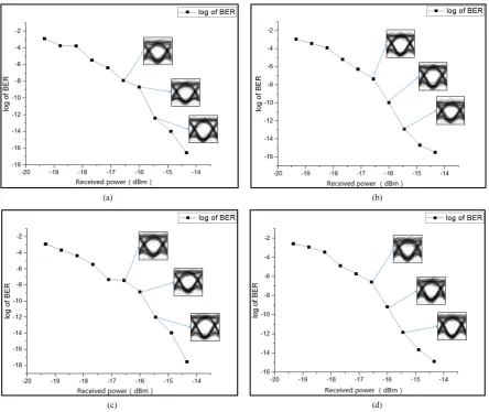
Figure 4. Four different dispersion compensation scheme transmission eye diagrams, and the BER curves (a) Pre-compen- sation (b) Post-compensation (c) Hybrid-compensation (pre+ post) (d) Hybrid-compensation (post+ pre).
[image:4.595.91.536.273.647.2]hybrid compensation (post + pre) is the best. Through the observation of eye diagram can be found, zero level has some disturbance because of LPF-ODB.
In order to scan the BER of different received power, an optical attenuator is added with the attenuation of 10 – 15 dB in simulation system. The diagram of the received power and BER is shown in Figure 4. According to the Q factor = 6 and BER = 1e−9 as boundary conditions, compared the transport eye diagrams when BER = 1e−9, 1e−8, and 1e−10. When the BER = 1e−9, the received power of pre-compensation and post-compensation both are −15.9d Bm, while hybrid compensation (pre+ post) and hybrid compensation (post+ pre) respectively are −16 dBm and −16.3 dBm. Obviously, hybrid compensation (post+ pre) has the minimum received power and the highest sensitivity.
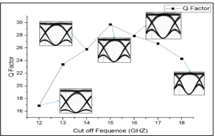
In this paper, the influence of the cut-off frequency of the LPF on the transmission performance is also ana-lyzed. As shown in the Figure 5, the cut-off frequency of the low-pass filter can be adjusted from 12 GHz to 18 GHz, and the image of Q factor increased firstly and then decreased. When the cut-off frequency is 15 GHz, the Q factor reached the highest value of 29.7, the eye diagram is the most clear, with the optimal transmission per-formance. At the same time, it can be seen that with the increase of the cut-off frequency, the zero level eye dis-turbance increased either.
4. Conclusion
A 40 Gbit/s high speed optical fiber transmission system with different dispersion compensation schemes is proposed in this paper, which based on LPF-ODB coded modulation and combinations of DCF, SMF and EDFA. At the same time, the transmission performance influenced by the cut-off frequency of the LPF is also analyzed, and the optimum transmission performance can be achieved when the cut-off frequency is 15 GHz. By compar-ing the Q factor, BER, eye diagram and receive sensitivity of dispersion compensation schemes, it is found that the Q factor of hybrid compensation (post+ pre) is of the best project, which has the lowest BER and the highest receiving sensitivity. Finally, it is determined that using the transmission performance of hybrid compensation (post+ pre) scheme is optimal.
Acknowledgements
[image:5.595.138.490.477.700.2]This work is partially supported by the National Natural Science Foundation of China (No. 61107064), Innova-tion Program of Shanghai Municipal EducaInnova-tion Commission (No. 15ZZ101), Leading Academic Discipline Project of Information and Communication Engineering (No. XXKZD1605), School Foundation (No. EGD14XQD01) of Shanghai Polytechnic University, College Students’ Science and Technology Innovation Project of Shanghai
Polytechnic University (No. 2016-xjkj-063), and College Student Innovation Activity Plan in Shanghai (No. 2013-sj-cxjh-028).
References
[1] Li, J. (2007) A Dispersion Compensation Structure Based on Dual-Cavity GT Interferometer. Huazhong University of Science &Technology, Wuhan. (In Chinese)
[2] Tokle, T. and Peucheret, C. (2003) Advanced Modulation Formats in 40Gbit/s Optical Communication Systems with 80km FibreSpans. Research Center Com, Technical University of Denmark.
[3] Cao, X. (2014) Optimization of Dispersion Compensation Scheme for Optical Fiber Communication System. Laser
Technology, 38, 101-104.
[4] Zou, Y.Q. (2012) Simulation of Different Compensation Methods of Dispersion Compensation Fiber. Optical
Instru-ments, 34, 11-16.
[5] Lyubomirsky, I. and Pitchumani, B. (2004) Impact of Optical Filtering Onduo-Binarytransmission. Photonics
Tech-nology Letters, IEEE, 16, 1969-1971. http://dx.doi.org/10.1109/LPT.2004.829751
[6] Fan, C.X., Zhan, D.Y., Xu, B.X., et al. (1995) Communications Principles. Beijing: Defense Industry Press.
[7] Li, Z.G. and Qiu, K. (2002) 40 GB/s Single Channel Optical Fiber Transmission System. University of Electronic
Science and Technology, 5, 441-446.
[8] Zhou, Z.Q., Tang, Y.L. and Xie, C.J. (2000) Optimum Schemes of Dispersion Compensation Transmission Systems Using Dispersion Compensation Fibers. Laser Technology, 24, 265-269. (In Chinese)
[9] Pan, Q. and Wen, A.J. (2006) Comparison in 40Gb/s Single Channel RZ Modulation Formats Optical Transmission Dispersion Compensating System. Optical Communication Technology, 30,61-62. (In Chinese)
[10] Ono, T., Yano, Y., Fukuchi, K., et al. (1998) Characteristics of Optical Duo-Binary Signals in Terabit/s Capacity, High-Spectral Efficiency WDM Systems. Journal of Lightwave Technology, 16, 788.
http://dx.doi.org/10.1109/50.669006
[11] Ramaswami, R. and Sivrajan, K.N. (2004) Optical Networks: A Practical Perspective. 2nd Edition. China Machine Press, Beijing.
[12] Shao, Y.F., Chen, L. and Zhu, J.Z. (2007) A New Modified Decoding Scheme of Optical Duo-Binary Transmission.
Journal of Communication, 2, 58-63, 74.
[13] Lu, Z.J., Wang, X.B. and Li, L. (2015) The Performance Analysis of Optical Double Binary Transmission in High Speed Optical Fiber System. Optical Communication Technology, 2, 34-37.
[14] Yu, J.J., Guan, K.J. and Yang, B.J. (1999) Numerical Simulation of a 10 Gbit/s Single Channel Long Distance Optical Communication System. Optical Communication Research, 1, 7-14, 18.