International Journal of Emerging Technology and Advanced Engineering
Website: www.ijetae.com (ISSN 2250-2459,ISO 9001:2008 Certified Journal, Volume 5, Issue 4, April 2015)
Open Embedded Architecture Robotic Controller
Prof. S. A. Lakhotiya
1, S.N. Raut
2Abstract— This Paper presents an open embedded hardware and software architecture for robotic control. Embedded implies integration of various functional blocks on one System-On-Chip board, for data acquisition, computation and control tasks, of relatively small size and low power consumption, compared to regular PC-based industrial controllers. It is industrial robot type independent, as long as the motors are equipped with incremental position encoders.
Generally the robotic controllers are developed for position control, without accomplishing integrally the requirements of tasks in which interactions with the environment occur. However, this is currently one of the main research areas in robotics. To consider this interaction the robot controller has to give priority to the force control time response, because in the instant of end-effectors contact with the surface, several forces act on the system. Depending on the speed and accelerations involved in the process ,damages or errors can occur .To avoid these effects ,compliances are inserted in tool or in surface of operation .But this is not efficient way to reduce damages because every time covers are use over the surface.
The objective of the proposed work will be to control the position and force of robotic arm in working environment to reduce the possible damages or errors to the environment in contact and diminishes the necessity of compliance in system.
Keywords– open embedded, robotic controller
I. INTRODUCTION
Current robotic applications are limited by the industry state of art of the manipulators control algorithms. The inclusion of force and vision feedbacks, the possibility of cooperation between two or more manipulators, the control of robots with irregular topology will certainly enlarge the industrial robotics applications. The development of control algorithms to this end brings the necessity of the use of controllers with open architecture.As a matter of fact, rapid prototyping, i.e., the capability of designing and testing new control algorithms in short time and with limited costs, is becoming a fundamental issue in industrial robotic applications. Notice that the degree of openness. In a robot controller may vary from one system to the other. Usually the control of some components of the system (e.g., the power system, the low level control) are proprietary and cannot be modified by the user, others may be considered open (e.g., the communication interface, the higher level control), i.e., are based on standard hardware and software
In recent decades, industrial robot control system have evolved from open-loop, position controlled to closed loop, adaptive controlled systems. The next generation of systems needs to address fast real-time response to cope with unpredictable human interaction, hazard safety issues, as well as increasing process speed demands. Currently, closed loop hardware systems are mainly dominated by microprocessors and digital ICs such as DSPs and RISC, delivering high-speed performance combined with the required flexibility inherent to all programmable solutions.
In this project an open embedded hardware and software controller architecture applied to an industrial robot platform. This architecture can be easily extended to control general multi-axis robot
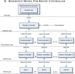
[image:1.612.324.583.358.614.2]II. REFERENCE MODEL FOR RBOTIC CONTROLLER
Figure 1: Open embedded architecture robotic controller
Task Layer:-The task layer has a mathematical
International Journal of Emerging Technology and Advanced Engineering
Website: www.ijetae.com (ISSN 2250-2459,ISO 9001:2008 Certified Journal, Volume 5, Issue 4, April 2015)
In this layer the user develops the control laws of position and/or force of the manipulator and it is possible to carry through the task simulation.
Integration layer:- In the integration layer the
concatenation and the organization of all the information coming from the sensors and to be sent to the superior layer are done. Control structure to this layer.
Communication layer:- The communication layer controls
the data transfer by managing the interface USB (Universal Serial 2, 0 Bus) and the industrial protocol CAN (Campus Area Network),
Interface layer:- The interface layer comprises the
embedded systems that carry out the control of the robotic joints, named motion controllers, each of these motor digital controllers decodes the corresponding encoder signal and. Each of these systems has an optical isolated interface to prevent any inadequate return to the processor.
Physical layer :-It is the most inferior layer which is used as the power unit of motor and angular position sensors. The industrial manipulator physical access (i occur physical layer, composed only by the input and output robot data channels. Usually, the actuator activation is realized indirectly, because, the controller signs only access the unit power that adapts this signs for the motors
III. PROPOSED WORK
[image:2.612.336.546.268.488.2]This project design embedded system for position and force control. In matlab GUI is created for every action. According the data is send to microcontroller through RS-232. Microcontroller process the data and output is given to motor driver so that robotic arm perform particular action
Fig 2 system block diagram
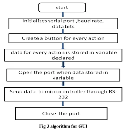
IV. ALGORITHIM FOR GUI
1
) for creating GUI in matlab firstly initialize serial port, baud rate, size of databits by commands = serial('COM1',baud rate,9600,databits,8);
2) open serial port which is initialize for sending data by command fopen()
3) create button for every controlling action
4) some variable is send for every controlling action by command fprint()
[image:2.612.53.265.529.626.2]Fig 3 algorithm for GUI
5) send data from pc to controller through RS-232
International Journal of Emerging Technology and Advanced Engineering
Website: www.ijetae.com (ISSN 2250-2459,ISO 9001:2008 Certified Journal, Volume 5, Issue 4, April 2015)
[image:3.612.55.288.129.439.2]V. ALGORITHIM FOR MICRO C
Fig 4 algorithm for micro c
1) initialize controller port used for communication 2) receive data from pc through Rx pin (PD0) of controller
3) process the data received
4) check the data received ,if it is for position control then
5) make base motor pin high
6) optical encoder disc is mounted on base motor which is move as per data received
7) insialize counter, it is incremented as encoder disc move
8) check whether incremented value of counter is equal to given value, if no continue the process
9) if yes stop motor and make base motor pin low
10) if receive data is for force control, then make grip motor pin high
11) inside the gripper limit switch is mounted ,so that when object come in contact with limit switch ,object is press continue until object grip tightly
12) when object grip tightly pick and place object as per required
13) stop process after completion of task
VI. TOOLS USED
1)Matlab for GUI:
Matlab is an efficient tool for creating graphical user interface. In this project GUI is used to create button for every action of robotic controller
2)Micro C for AVR:-
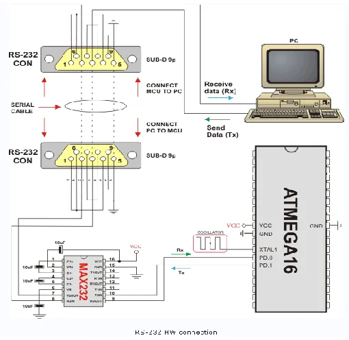
The mikroC PRO for AVR is a powerful, feature-rich development tool for AVR microcontrollers. It is designed to provide the programmer with the easiest possible solution to developing applications for embedded systems, without compromising performance or control. It receive UART data from pc. MikroC PRO for AVR allows you to quickly develop and deploy complex applications.UART hardware module is available with a number of AVR MCUs. Mikro C PRO for AVR UART Library provides comfortable work with the Asynchronous (full duplex) mode. It can easily communicate other devices via RS-232 protocol as shown in fig below
Fig 5 communication through RS-232
3)Steps for writing code in mikro C
[image:3.612.325.580.368.616.2]International Journal of Emerging Technology and Advanced Engineering
Website: www.ijetae.com (ISSN 2250-2459,ISO 9001:2008 Certified Journal, Volume 5, Issue 4, April 2015)
2)Use included mikroC PRO for AVR libraries to dramatically speed up the development: data acquisition, memory, displays, conversions, communication etc.
3)Monitor your program structure, variables, and functions in the Code Explorer.
4)Generate commented, human-readable assembly, and standard HEX compatible with all programmers.
5)Inspect program flow and debug executable logic with the integrated Software Simulator.
6)Get detailed reports and graphs: RAM and ROM map, code statistics, assembly listing, calling tree, and more.
7)mikroC PRO for AVR provides plenty of examples to expand, develop, and use as building bricks in your projects.
4)Atmega 32 microcontroller:
The Atmega32A is a low-power CMOS 8-bit microcontroller based on the AVR enhanced RISC architecture. By executing powerful instructions in a single clock cycle, the Atmega32.It achieves throughputs approaching 1 MIPS per MHz allowing the system designer to optimize power consumption versus processing speed.
5)Optical encoder disc
The Optical Shaft Encoder uses an infrared light sensor to detect illumination from an infrared LED passing through slots cut in the circumference of a rotating wheel use to the performance and reliability advantages of the semi-conductor technology they incorporate, optical encoders are the preferred solution in many common computer, industrial, and automotive applications. Optical encoders also benefit from ease of customization, are suitable to numerous environments, and suffer no effects from high levels of stray magnetic fields. The basic construction of an incremental encoder is shown to the right. A beam of light emitted from an LED passes through a transparent disk patterned with opaque lines and is picked up by a photodiode array.
Fig:-6 optical encodr disc and its working operation
International Journal of Emerging Technology and Advanced Engineering
Website: www.ijetae.com (ISSN 2250-2459,ISO 9001:2008 Certified Journal, Volume 5, Issue 4, April 2015)
6)Force sensor:
It is force sensing register having polymer thick film which exhibits a decrease in resistance with increase in force applied to active force
7)RS 232
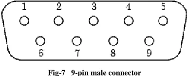
Over the years, several serial port interface standards for connecting computers to peripheral devices have been developed. These standards include RS-232, RS-422, and RS-485 all of which are supported by the serial port object. Of these, the most widely used standard is RS-232, which stands for Recommended Standard number 232. Serial ports consist of two signal types: data signals and control signals. To support these signal types, as well as the signal ground, the RS-232 standard defines a 25-pin connection. However, most PCs and UNIX platforms use a 9-pin connection. In fact, only three pins are required for serial port communications: one for receiving data, one for transmitting data, and one for the signal ground.
[image:5.612.71.264.390.468.2]The pin assignment scheme for a 9-pin male connector on a DTE is given below
Fig-7 9-pin male connector
The serial data format includes one start bit, between five and eight data bits, and one stop bit. A parity bit and an additional stop bit might be included in the format as well. The diagram below illustrates the serial data format.
8) L298 motor driver
The L298 is an integrated monolithic circuit in a 15-lead Multiwatt and PowerSO20 packages. It is a high voltage, high current dual full-bridge driver designed to accept standard TTL logic levels and drive Inductive loads such as relays, solenoids, DC and stepping motors. Two enable inputs are provided to enable or disable the device independently of the input signals.
The emitters of the lower transistors of each bridge are connected together and the corresponding external terminal can be used for the connection of an external sensing resistor. An additional supply input is provided so that the logic works at a lower voltage. L298 motor driver accept 5v from microcontroller and convert it into 12v which is the required voltage for motor of robotic arm
Fig 8 motor driver L298 IC
VII. ADVANTAGES AND LIMITATIONS
1) Advantages
1) Provides flexibility in implementation, integration with personnel computer and programming in high level.
2) High capacity of processing 3) Improve productivity.
4) High connectivity with other system.
5) Robot scan work in hazardous environments robots need no environmental comfort
6) Robots work continuously without any humanity needs and illnesses robots have repeatable precision at all times robots can be much more accurate than humans; they may have mili or micro inch accuracy.
7) Robots and their sensors can have capabilities beyond that of humans Robots can process multiple stimuli or tasks simultaneously, humans can only one.
8) Robots replace human workers who can create economic problems
2) Limitations
1) Less lifting capacity
International Journal of Emerging Technology and Advanced Engineering
Website: www.ijetae.com (ISSN 2250-2459,ISO 9001:2008 Certified Journal, Volume 5, Issue 4, April 2015)
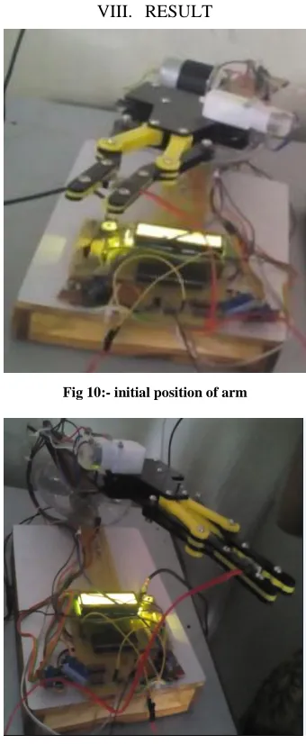
[image:6.612.82.252.135.548.2]VIII. RESULT
[image:6.612.84.255.139.346.2]Fig 10:- initial position of arm
Fig 11:-final position of arm
IX. CONCLUSION
In this work we considered a new reference model for a control system function Architecture applied to open-architecture robot controllers. The proposed approach was applied for integrally developing of a five-layer based open-architecture robotic controller considering interaction tasks. The architecture uses parallel and distributed processing techniques and circumvents the necessity of compliance in system, allowing a real-time processing of the application and the total information control.
Old manipulator retrofitting considers the problem of including controllers with new functionalities as force control.
The main characteristics of these systems are high-stiffness and position control. These characteristics restrict response time of the system. Therefore, an open-architecture system can be projected to operate in real-time. The proposed reference model for open-architecture robot controllers was experimentally validated including the implementation of an indirect force control strategy in the robot controller. Practical tests have shown the interest of the proposed architecture in terms of controller flexibility, costs and maintenance and high capacity of processing. This reference model clarifies the concept of robot controller and explains the internal modules that compose robot control unit. The system decomposition makes possible the optimization of internal modules for a specific task, e.g. pick tasks. In this way, it is efficient system which can control position with force through embedded system
REFERENCES
[1] IS Association, 1990, .IEEE Standard 802.4: Information processing systems-Local area networks . Token passing bus access method and physical layer specifications ..
[2] Ford, W., 1994, .What is an Open Architecture Robot Controller?", 9th IEEE Int. Symp. On Intelligent Control, pp.
[3] Lages, W.F., Henriques, R.V.B., Bracarense, A. Q., 2003, .ArquiteturaAbertapara Retrofitting de Robôs. (inportuguese), Manet Notes Workshop, Bragança Paulista, São Paulo, Brazil
[4] Sciavicco, L., Siciliano, B., 2004, .Modeling and control of robot manipulators., The McGraw-Hill Companies
[5] Raposo, E., 2006, .Um Modelo Aberto para Robôs., PhD. Thesis (in portuguese), Universidade Federal de SantaCatarina, Department of Mechanical Engineering, SC, Brazil
[6] M. Prats, S. Wieland, T. Asfour, A. P. del Pobil, and R. Dillmann,“Compliant interaction in household environments by the Armar-IIIhumanoid robot,” in IEEE-RAS InternationalConference on HumanoidRobots, 2008, pp. 475–480.
[7] C. Carozzi, G. Magnani, and S. Nicolodi, “Implementation of sensorbasedcontrol algorithms in an industrial robot controller,” ControlEngineering Practice, vol. 3, no. 9, pp. 1307–1313, 1995. [8] J. S. Gu and C. W. de Silva, “Development and implementationof a
real-time open-architecture control system for industrial robotsystems,” Engineering Applications of Artificial Intelligence, vol. 17,no. 5, pp. 469–483, 2004