International Journal of Emerging Technology and Advanced Engineering
Website: www.ijetae.com (ISSN 2250-2459,ISO 9001:2008 Certified Journal, Volume 5, Issue 4, April 2015)
367
Moving Target Detection, Tracking and Destruction Based on
Shape and Color
Apurva Pawar
1, Prof. P. P. Kulkarni
21,2JSPM’s Bhivrabai Sawant College of Engineering & Research, Pune, India.
Abstract—Now a days the object tracking is an important task within the field of computer vision. Also the increasing need for automated video analysis has generated a great deal of interest in object tracking algorithms. Therefore in this paper shows a system, which will automatically recognize, track and destroy the intruding object that will be captured by camera. This system can be used in the military application where it is hard for soldiers to fight. This system will be installed at a particular place. It will have a camera, which will capture the area under surveillance. The system will then detect the intrusion and recognize the object. Now the original image which we have taken without intruding object is compared with the image that has intruding object then after comparison, if the features of object are same as the features of object in the data base. Then the intruding object will be tracked and get destroyed by bullets and bombs. This will help to get very tight security without involvement of human resource.
Keywords— Object tracking, Object reorganization, Intrusion object.
I. INTRODUCTION
Object tracking is an important task within the field of computer vision. The proliferation of high-powered computers, the availability of high quality and inexpensive video cameras, and the increasing need for automated video analysis has generated a great deal of interest in object tracking algorithms. In its simplest form, tracking can be defined as the problem of estimating the trajectory of an object in the image plane as it moves around a scene. In other words, a tracker assigns consistent labels to the tracked objects in different frames of a video [2]. Additionally, depending on the tracking domain, a tracker can also provide object centric information, such as orientation, area, or shape of an object.
In this paper the intrusion detection, track and destroy the intruding object is present. The system will be mounted at some suitable place from which complete and clear view of the area under surveillance can be captured with camera. Thus the image will be captured; processed and desired action will be performed on it. Object segmentation separates regions of interest in image data that identify real world objects.
Segmenting and tracking regions of arbitrary size within a scene allow the application to focus on more complex tasks like object recognition within a smaller spatial domain of the entire spatial scene which reduces the processing time required to identify the object of interest. Reducing the spatial domain of the image decreases the computational resources necessary for the detailed analyses required for object recognition.
For Object Tracking and Classification basic thing is to obtaining an initial mask for a moving object, and to preprocess the mask. Normally the mask is affected by ―salt-and-pepper‖ noises. We apply morphological filters based on combinations of dilation and erosion to reduce the influence of noise, followed by a connected component analysis for labeling each moving object region.
Very small regions are discarded. At this stage we calculate the following features for each moving object region: bounding rectangle: the smallest isothetic rectangle that contains the object region. We keep record of the coordinate of the upper left position and the lower right position, what also provides size information (width and height of each rectangle).
Color: the mean R G B values of the moving object.
Center: we use the center of the bounding box as a simple approximation of the centroid of a moving object region.
Velocity: defined as movement of number of pixels/second in both horizontal and vertical direction.
In order to track moving objects accurately, especially when objects are partially occluded, and the position of the camera is not restricted to any predefined viewing angle, these features are actually insufficient. We have to add further features that are robust and which can also be extracted even if partial occlusion occurs.
International Journal of Emerging Technology and Advanced Engineering
Website: www.ijetae.com (ISSN 2250-2459,ISO 9001:2008 Certified Journal, Volume 5, Issue 4, April 2015)
368
Prior knowledge about the number and the size of objects, or the object appearance and shape, can also be used to simplify the problem.
Rest of the paper is organized as follows. In the next section II shows the hardware and software used while designed. Section III shows the development of proposed system. Section IV shows the experimental results and finally section V concludes this paper.
II. HARDWARE AND SOFTWARE USED
This section describes the different components and software used in this proposed moving target detection, tracking and destruction system.
A. Image Processing Hardware
A computer with Intel 1.6 GHz processor and 512MB RAM was used as Image Processing hardware. Camera is connected to this PC via USB port. The image acquired by camera is processed by this hardware and result of processing is sent to Microcontroller. Microcontroller will control the angle of rotation of servo motor to position cannon accordingly. When an object is observed form far distance, its peripheral shape and its color are the prominent feature which distinguishes it from background and other objects. So while extracting features of the object for identification, its peripheral shape and color are considered, instead of other features like texture and other minute details.
1. Camera
Camera used for experimentation purpose is ―i-ball face2face, a USB webcam, with 640 by 480 resolution and 64M color depth. A Night-Vision Camera and camera with different resolution and color depth can be used depending upon requirement of application. Camera is fixed on the system and should not move from its place once background is captured, otherwise it will adversely affect accuracy of the system as subtraction is used to detect intruding object. iBall Face2Face C1.3 web camera with interpolated 1.3MP resolution and 5G Wide angle lens provides smooth video and lets you enjoy the clarity of web video.
2. Microcontroller
Microcontroller used is a NXD P89V51RD2. It is used to run the servo motor accordingly to track the moving object. Micro controllers PWM feature to control servo motors. In this way the PWM with automatically generate signals to lock servo and the CPU is free to do other tasks.
3.Servo Motor
The output of controller is given as input to motor. Servo motor is used for the tracking purpose of a moving object.
4.RS232
RS232 is used for serial communication between circuit and PC. It uses only one or two data lines to transfer data and is generally used for long distance communication. In serial communication the data is sent as one bit at a time.
This article describes the interfacing of 8051
microcontroller with a computer via serial port, RS232. Serial communication is commonly used in applications such as industrial automation systems, scientific analysis and certain consumer products.
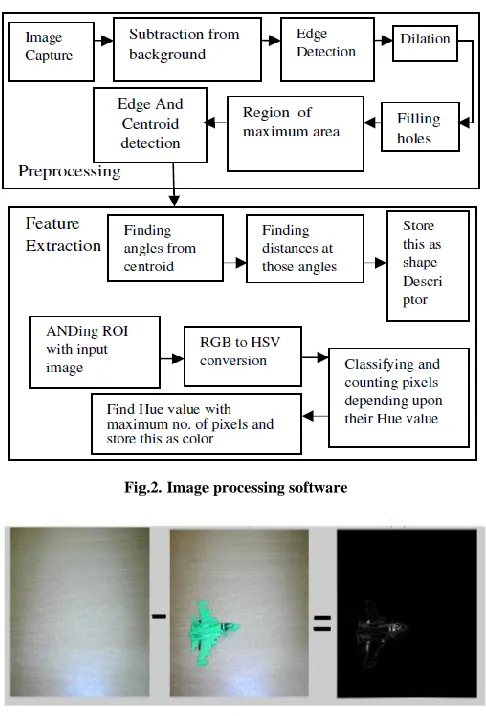
B. Image Processing Software
This section describes the different software that is used in this proposed moving target detection, tracking and destruction system.
1.Color Space
A color space is a method by which we can specify, create and visualize color. As humans, we may define a color by its attributes of brightness, hue and colorfulness. A computer may describe a color using the amounts of red, green and blue phosphor emission required to match a color. A printing press may produce a specific color in terms of the reflectance and absorbance of cyan, magenta, yellow and black inks on the printing paper. A color is thus usually specified using three co-ordinates, or parameters. These parameters describe the position of the color within the color space being used. Different color spaces are better for different applications, for example some equipment has limiting factors that dictate the size and type of color space that can be used.
2.HSL (Hue Saturation and Lightness)
This represents a wealth of similar colour spaces; alternative names include HSI (intensity), HSV (value), HCI (chroma / colorfulness), HVC, TSD (hue saturation and darkness) etc. Most of these colour spaces are linear transforms from RGB and are therefore device dependent and non–linear. Their advantage lies in the extremely intuitive manner of specifying colour. It is very easy to select a desired hue and to then modify it slightly by adjustment of its saturation and intensity.
International Journal of Emerging Technology and Advanced Engineering
Website: www.ijetae.com (ISSN 2250-2459,ISO 9001:2008 Certified Journal, Volume 5, Issue 4, April 2015)
369
However the exact conversion of RGB to hue, saturation and lightness information depends entirely on the equipment characteristics. Failure to understand this may account for the sheer numbers of related but different transforms of RGB to HSL, each claimed to be better for specific applications than the others. HSV color space transforms standard RGB (Red, Green, Blue) color space into a new color space comprised of Hue, Saturation and Intensity (Value).
III. DEVELOPMENT OF SYSTEM
[image:3.612.326.569.331.689.2]This system is proposed for detecting intrusion, tracking intrusion object and destroying it. The system will be fixed at suitable place, from which complete and clear view of the area under surveillance can be captured by the camera. The system is provided with high resolution camera, image processing hardware, microcontroller and a servomotor and other supplementary hardware and mechanisms.
Fig.1. Basic Block diagram of complete system
Image Processing Algorithm will acquire images captured by camera after some predefined interval of time. Then it will process every captured image for detecting intrusion. If intrusion is detected Image Processing Hardware will extract the features of that intruding object and compare them with features of objects stored in database. We have collected database for the objects those are to be destroyed. System will track that object to calculate its velocity of motion. This velocity information is needed to decide the angle and time instant at which projectile is to be launched at intruding object to destroy it. Position of the intruding object in the form of x-y
co-ordinate is found and sent to microcontroller.
Microcontroller will control the angle of rotation of two Servo Motors to position the cannon aiming at the intruding object. At last cannon will get fired.
A. Steps Involved in Image Processing
When an object is observed form far distance, its peripheral shape and its color are the prominent feature which distinguishes it from background and other objects. So while extracting features of the object for identification, its peripheral shape and color are considered, instead of other features like texture and other minute details.
The complete algorithm for this prototypic system is
implemented in Matlab7.2 software using Image
Processing Toolbox.
1.Pre-processing
Background image has to be captured after installing camera at its place and care must be taken that camera shouldn’t move once background is captured. Subtraction between background image and current image obtained from camera is used to detect intrusion. If there is no intrusion then previously captured background image and image taken from camera at any later time will have no difference and result of subtraction will be zero (a complete black image). But if some object has intruded in the scene then difference between those two images will be the object itself and is not zero, as in previous case. This subtraction process is shown in Fig.3.
Fig.2. Image processing software
[image:3.612.51.286.357.410.2]International Journal of Emerging Technology and Advanced Engineering
Website: www.ijetae.com (ISSN 2250-2459,ISO 9001:2008 Certified Journal, Volume 5, Issue 4, April 2015)
370
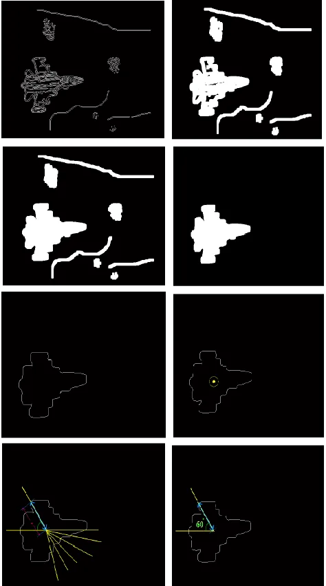
Result of subtraction is not suitable for feature extraction as outer edges of intruding object are not clearly visible. This problem can be depicted from Fig.4. This is image obtained from inverting the result of subtraction which prominently indicates above mentioned problem. So this result of subtraction has to be pre-processed before feature extraction.
Preprocessing involves following steps. As subtraction is obtained by subtracting color images, result of subtraction is also a color image. It is converted into binary image as shown in Fig.4.Our final aim of image reprocessing is to obtain image shown in Fig.4 which is suitable for feature extraction. Canny edge detection is function is operated on Binary Image to detect the edges of the intruding object depending upon threshold chosen adaptively. Correct choice of threshold leads to proper edge detection, which will increase overall accuracy. Problem of unclear and broken boundary as depicted in the Fig.4 is present till this stage. To remove this problem image is dilated with some suitable mask to join these broken edges. The output of dilation is shown in Fig.4. Holes in binary images are black portion of image surrounded by white boundary. These holes are filled with filling operation to get number of different unconnected white areas. These white areas are related to different objects in image. At this stage, we get various unwanted white regions other than white region related to the intruding object. These unwanted white of capturing images, camera imperfections etc. These unwanted regions have inherent property that their area is lesser than intruding object. So only white region with maximum area is kept which corresponds to intruding object as shown in Fig.4. Edge of this image is detected using canny edge detection method. This edge corresponds to boundary of intruding object with some error introduced due to dilation operation. Error that is less than 13% is proved to be acceptable. Therefore the mask for dilation operation must be chosen adaptively depending upon size of objects. This edge detected image is Suitable for shape
detection. Fig 4.Complement of subtracted image, Binary Image, Edge Detected,
Dilated, Filling Holes, Object with Maximum Area, Edge Detection of Previous Image, Centroid Obtained and Located, Finding distance
between centroid, points of edge located at various angles
1.Feature Extraction
Shape Description: Shape of an object is nothing but distances of all the points on its boundary from some reference point. This reference point can be centroid (center of mass) of an object Centroid of object does not change though object is rotated. Center of circle is its centroid and distances of all points from centroid are equal.
[image:4.612.325.562.138.564.2]International Journal of Emerging Technology and Advanced Engineering
Website: www.ijetae.com (ISSN 2250-2459,ISO 9001:2008 Certified Journal, Volume 5, Issue 4, April 2015)
371
For square it will be different case. Similarly if we measure distances of some points on the boundary of an object as shown in Fig.4.then we can get shape descriptors. In our case we have considered those points on the boundary of the object which are separated by angle of 10 degrees. All the angles are measured from centroid of the object.
Thus we have calculated 36 distances corresponding to 36 different angles separated by 10 degrees. This angle separation can be reduced in order to increase accuracy. But along with reduction in angle separation, number of readings will increase and it will increase computation time. So there is tread off between ability of system to work in real time and its accuracy. Normalization of the data obtained above is done in order to enable scale invariance. Object viewed from various distances will not differ in their shape. But they will differ in their sizes.
Normalization will enable comparison between objects those are present at various distances from camera. Normalization is done by dividing all above 36 distances readings by largest distance reading. This results in get all 36 shape descriptors readings to range from 0 to1. Again shape descriptors obtained above can be made invariant to rotation of the object. To make it starting point or rotation invariant, circular shifting of readings (which is used in chain codes) can be implemented. This enables to compare objects having different rotational orientation. Thus we have made this system rotation invariant and scale invariant. Thus shape descriptor of the object is obtained.
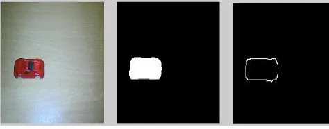
[image:5.612.329.566.140.234.2]Color Detection: If we observe some object from far distance, we consider its gross features instead of fine details. If that object is having different colors on its different parts then the color which is occupying maximum area of that object is considered, and it is said that object that object is of that color. e.g. shows object is having green color covering most of its parts, and blue and black colors covering only some of its portion. So color of that object is considered to be green only. To find color of the object, color image obtained from camera is logically ANDed with preprocessed image shown in Fig.4. Result of ANDing is shown in Fig.5.
Fig.5.Object, HSV transformation, Only Hue plane
Now this resulting image is converted into HSV image as shown in Fig.6. Hue plane of HSV image contains only color information. All the values of Hue plan lies between 0 to 1. Depending upon their values, color is detected. E.g. red, green and blue colors can be distinguished as in HSV plane as red pixels have values >0.8 and <0.15, green pixels have values >0.15 but <0.48, blue pixels have values >0.48 but <0.8. Thus second gross feature of the objects that is its color is detected.
Color and shape detection is also performed on database images. If match between any on the database object and intruding object is found then that object is said to be recognized. And it has to be destroyed. Fig.6. shows result of preprocessing and feature extraction on some sample database image
Fig 10. Preprocessing and feature extraction
[image:5.612.327.564.440.533.2]International Journal of Emerging Technology and Advanced Engineering
Website: www.ijetae.com (ISSN 2250-2459,ISO 9001:2008 Certified Journal, Volume 5, Issue 4, April 2015)
372
The servo controller will adjust the viewing field of the camera by applying the adjustment output as a pulsed width modulated signal to the servo motors. Adjustment output will be calculated by the software in the acquisition feedback loop to center the object found with the specified user constraints. A camera mount will be fabricated for the camera as well as housing for the servos this allows a range of motion for tracking moving objects
IV. EXPERIMENTAL RESULTS
The detail steps of proposed system are described in this section. The simulation results show the description of the object. There are two characteristics are consider in this paper to give the description of the object, viz. shape and color.
a) b)
c) d)
Fig.11.Simulation results when color and shape both not matched. a) Background Image, b) Test Image, c) Object Image, d) command
window of Mat lab.
Fig.11.shows the simulation results when color and shape both not matched.
a) b)
c) d)
Fig.12.Simulation results when color and shape both are matched. a) Background Image, b) Test Image, c) Object Image, d) command
window of Mat lab.
Fig.12.shows the simulation results when color and shape both not matched.
a) b)
c) d)
Fig.13.Simulation results when color is matched and shape is not match. a) Background Image, b) Test Image, c) Object Image, d)
International Journal of Emerging Technology and Advanced Engineering
Website: www.ijetae.com (ISSN 2250-2459,ISO 9001:2008 Certified Journal, Volume 5, Issue 4, April 2015)
373
Fig.13.shows the simulation results when color is matched and shape is not match.
a) b)
c) d)
Fig.14.Simulation results when color isn’t matched but shape is matched. a) Background image, b) test image, c) object image, d)
command window of mat lab.
Fig.14. shows the simulation results when when color isn’t matched but shape is matched.
V. CONCLUSION
In this paper, an automated surveillance system is described, which includes the following four main building blocks: moving object detection, object tracking and event recognition. In this thesis we presented a set of methods and tools for a ―smart‖ visual surveillance system.
We implemented three different object detection algorithms and compared their detection quality and time-performance. The adaptive background subtraction scheme gives the most promising results in terms of detection quality and computational complexity to be used in a real-time surveillance system with more than a dozen cameras.
However, no object detection algorithm is perfect, so is our method since it needs improvements in handling darker shadows, sudden illumination changes and object occlusions. Higher level semantic extraction steps would be used to support object detection step to enhance its results and eliminate inaccurate segmentation.
The proposed whole-body object tracking algorithm successfully tracks objects in consecutive frames. Our tests in sample applications show that using nearest neighbor matching scheme gives promising results and no complicated methods are necessary for whole-body tracking of objects.. However, due to the nature of the heuristic we use, our occlusion handling algorithm would fail in distinguishing occluding objects if they are of the same size and color. Also, in crowded scenes handling occlusions becomes infeasible with such an approach, thus a pixel-based method, like optical flow is required to identify object segments accurately.
We proposed a novel object classification algorithm based on the object shape similarity. The method is generic and can be applied to different classification problems as well. Although this algorithm gives promising results in categorizing object types, it has two drawbacks: (a) the method requires effort to create a labeled template object database (b) the method is view dependent. If we could have eliminated (b), the first problem would automatically disappear since one global template database would suffice to classify objects. One way to achieve this may be generating a template database for all possible silhouettes of different classes. This would increase the computational time, but may help to overcome the need for creating a template database for each camera position separately.
REFERENCES
[1] Kouji MURAKAMI, Kazuya MATSUO, Tsutomu HASEGAWA, Ryo KURAZUME,―Position Tracking and Recognition of Everyday Objects by using Sensors Embedded in an Environment and Mounted on Mobile Robots‖ pp. 2210-2216
[2] Kwak, Jae Chang,‖ Implementation of object recognition andtracking algorithm on real-time basis‖ pp. 2000-2003
[3] PankajBongale,‖ Implementation of 3D Object Recognition and Tracking‖ pp. 77-79
[4] Kuk Cho,‖ Real-time 3D Multiple Occluded Object Detection and Tracking‖