International Journal of Emerging Technology and Advanced Engineering
Website: www.ijetae.com (ISSN 2250-2459, ISO 9001:2008 Certified Journal, Volume 5, Issue 6, June 2015)
286
CFD Analysis of the Effect of Defects in Welding and Surface
Finish on the Performance Characteristics of Venturimeter
Arun R
1, Yogesh Kumar K J
2, V Seshadri
31M.Tech Student, Thermal Power Engineering, MIT-Mysore, India 2
Assistant Professor, 3Professor (Emeritus), Department of Mechanical Engineering, MIT-Mysore, India
Abstract- The venturimeter is a typical obstruction type flow meter, widely used in industries for flow measurements. The ISO standard (ISO-5167-1) provides the value of discharge coefficients for the classical machined venturimeters in turbulent flows with Reynolds number above 2x10⁵ at standard conditions. In the present work, an attempt is made to study and prepare a computational model of a venturimeter, which can be used as an efficient and easy means for predicting the discharge coefficients at different non-standard conditions. The computational fluid dynamics (CFD) software ANSYS FLUENT-14 has been used as a tool to perform the modeling and simulation of venturimeter. Simulations were carried out for a standard venturimeter and the results were validated with the standards. Further the focus of the study was directed towards various defects such as defects in welding and wall surface finish. It is observed that the inaccuracies in machining of weld material residuals and wall roughness also affect the actual flow measurements by increasing the differential pressure drop across the two pressure taps if they are beyond certain allowable limits. The present analyses have been able to quantify these limits. From the analysis, it is suggested that the maximum allowable weld imperfection would be h/D<10-3 and the maximum allowable roughness height (ks/D) should be less than 10-4 so that the discharge coefficient is not significantly affected. Hence while using the venturimeter; it is necessary to ensure a smooth interior surface so that the accuracy of the flow measurement is not affected.
Keywords- Coefficient of discharge (Cd), Computational
Fluid Dynamics (CFD), Geometrical inaccuracies, Venturimeter, Wall roughness, weld material.
I. INTRODUCTION
The flow meters are being widely used in the industries to measure the volumetric flow rate of the fluids. These flow meters are usually differential pressure type, which measure the flow rate by introducing a constriction in the flow. The pressure difference caused by the constriction is used to calculate the flow rate by using Bernoulli‟s theorem.
If any constriction is placed in a pipe carrying a fluid, there will be an increase in the velocity and hence the kinetic energy increases at the point of constriction. From the energy balance equation given by Bernoulli‟s theorem, there must be a corresponding reduction in the static pressure.
Thus by knowing the pressure differential, the density of the fluid, the area available for flow at the constriction and the discharge coefficient, the rate of discharge from the constriction can be calculated. The discharge coefficient „Cd‟ is the ratio of actual flow to the
theoretical flow. The widely used flow meters in the industries are orifice meter, venturimeter and Pitot tube. Venturimeter and orifice meter are more convenient and frequently used for measuring flow in an enclosed ducts or channels.
Venturi meters are commonly used in single and multiphase flows. The objective of the present work is to study the performance characteristics of venturimeter with different geometrical inaccuracies due to manufacturing defects such as improper machining of weld material residuals, wall surface roughness and also to evaluate how well CFD modeling can predict the experimental results.
A. Venturimeter:
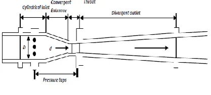
[image:1.595.327.536.517.611.2]The venturimeter is also an obstruction type flow meter named in honor of Giovanni Venturi (1746-1182), an Italian physicist who first tested conical expansion and contraction.
Fig.1: Venturimeter
International Journal of Emerging Technology and Advanced Engineering
Website: www.ijetae.com (ISSN 2250-2459, ISO 9001:2008 Certified Journal, Volume 5, Issue 6, June 2015)
287
Because of the smoothness of the contraction and expansion section of venturi, the irreversible pressure loss is low. However, in order to obtain a significant measurable pressure drop, the downstream pressure tap is located at the throat of the venturimeter. In comparison of venturimeter with the orifice meter, the pressure recovery is much better for venturimeter than for the orifice plate, but there is no complete pressure recovery. Pressure recovery is measured as the pressure difference between inlet and outlet.
As per ISO 5167-1, the mass flow rate in a Venturi meter (Qm) is given by:
√
√
Where:
Cd = Venturimeter discharge coefficient
= Venturimeter beta ratio, d/D d = Venturimeter throat diameter
D = Upstream pipe dia. of Venturi convergent section
P1 = Static pressure at the upstream pressure tap
= Turbulent dissipation
P2 = Static pressure at the Venturi throat tap
= Fluid density at the upstream tap location
Equation (2) is based on the assumptions that the flow steady, incompressible, and inviscid flow (no frictional pressure losses) and turbulent flow profiles (i.e., “flat” flow profiles) occur at the pressure tap locations. However in order to take into account the real fluid effects like viscosity and compressibility to empirical coefficients Cd and are introduced in the equation. In this paper we are considering only incompressible flow therefore = 1.
Over the years the venturimeters have been used for metering the different flows (liquid, gas, mixed flow). The performances of these meters in terms of value of discharge coefficient and pressure loss have been investigated by several researchers. Gordon Stobie et al [1] made a performance study on effect of erosion in a Venturi Meter with Laminar and Turbulent Flow and measurement of discharge coefficient at low Reynolds Number. Naveenji Arun et al [6] conducted a CFD analysis to predict the discharge co-efficient of venturimeter as a function of Reynolds number with different beta ratios for single phase non-Newtonian flows. C. L. Hollingshead et al [2], conducted experimental studies on discharge coefficients of venturi and validated using numerical analysis.
T. Nithin et al [4] investigated the effect of divergence angle on the total and differential pressure drops for various values of angle of divergence and inlet velocities for the different venturi profiles.
II. CFDMODELING AND SIMULATION
CFD modeling is a useful tool to gain an additional insight into the physics of the flow and to understand the test results. The objective of the CFD work is to model the flow using 2D venturimeter geometry to study the flow characteristics that is similar to the practical situation.
Model Description: The ANSYS FLUENT-14 CFD code is used to model and simulate the flow through venturimeter. The venturimeter geometry was modeled as a 2D-axisymmetric domain using unstructured grid. The dimensions of the geometry were taken from the ISO-5167-1 and no pressure taps were included in the CFD geometry.
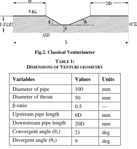
[image:2.595.324.551.404.652.2]The simulation was carried out for a standard classical venturimeter with following dimensions (see Table. 1) and the model is shown in the Fig.2
Fig.2. Classical Venturimeter
TABLE 1:
DIMENSIONS OF VENTURI GEOMETRY
Variables Values Units
Diameter of pipe 100 mm
Diameter of throat 50 mm
-ratio 0.5 ---
Upstream pipe length 6D mm
Downstream pipe length 20D mm
Convergent angle (θ1) 21 deg
Divergent angle (θ2) 9 deg
International Journal of Emerging Technology and Advanced Engineering
Website: www.ijetae.com (ISSN 2250-2459, ISO 9001:2008 Certified Journal, Volume 5, Issue 6, June 2015)
288
Fig.3. Grids used for venturimeter simulation
III. VALIDATION OF CFDMETHODOLOGY
For validation of CFD methodology a standard classical machined venturimeter was selected. As per ISO-5167-1, the standard dimensions of a classical venturimeter with a machined convergent section are in the ranges of,
50mm < D <250mm 0.4 < < 0.75 2x10⁵ < Re < 1x10⁶
Based on the standard limits, a venturimeter with D=100mm and =0.5 was constructed as a 2D axis symmetric geometry. In the simulation procedure, the process of grid generation is a very crucial step for better accuracy, stability and economy of prediction. Based on mesh convergence study, it is revealed that a total of quadrilateral elements beyond 120000 yields a consistent result. Hence a total of 130546 quadrilateral elements were used.
In simulating a fully-developed flow through Venturi meter inlet, a turbulent velocity profile was prescribed at the pipe inlet located six D upstream of the upstream pressure tap. This ensured a fully-developed turbulent velocity profile at the Venturi upstream pressure tap location. In the modeling, mass, momentum, energy conservation equations (if necessary) must be satisfied.
The governing equations for steady incompressible flows are:
Conservation of mass equation, this equation is valid for both incompressible and compressible flows.
Conservation of momentum equation and for steady flow it is written as,
( )
( )
( )
Where „p‟ is the static pressure, „ g‟ is the gravitational body force.
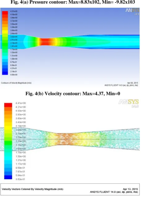
The Realizable k- turbulence model with standard wall conditions was selected to model the flow domain as it is superior to the Standard k- model for the prediction of separated turbulent flows. Velocity at the inlet was specified as 1m/s and at outlet the gauge pressure was set to zero. The heat transfer from the wall of the domain was neglected. The solution was computed in the commercial CFD code Fluent 14, in which the pressure based solver, was selected for this particular case. The results obtained from the CFD simulations (see Table 2) were very close to the Cd value specified in the standard ISO 5167-1 and hence CFD methodology was validated. The pressure and velocity contours along with velocity vectors are as shown in the Fig. 4. From the contours it is clearly observed that the velocity is increased in the convergent section with the corresponding reduction in the pressure, maximum velocity (minimum pressure) is recorded at the throat and velocity reduces in the divergent section while the pressure recovery occurs in this section. The vector plot shows the flow pattern of the fluid particle inside the venturimeter.
TABLE 2
COMPARISON OF CD VALUE OF ISO5167-1 AND CFDCD VALUE
Reynolds Number
Cd specified in
ISO 5167-1
Cd obtained from
CFD
International Journal of Emerging Technology and Advanced Engineering
Website: www.ijetae.com (ISSN 2250-2459, ISO 9001:2008 Certified Journal, Volume 5, Issue 6, June 2015)
289
Fig. 4(a) Pressure contour: Max=8.83x10², Min= -9.82x10³
Fig. 4(b) Velocity contour: Max=4.37, Min=0
Fig. 4(c) Velocity vectors: Max=4.41, Min=3.62
Fig.4. Contours and vectors
IV. RESULTS AND DISCUSSIONS
CFD simulations were performed over a wide range of conditions. Venturimeter discharge coefficients were calculated from the CFD predicted venturi pressure drops. The simulations were done by keeping constant Reynolds number. Initially the simulation was carried out for a standard classical machined venturimeter and the CFD results were validated with the standards. Further the studies were concentrated on different manufacturing defects and are as follows:
A. Effect of welding defects on discharge coefficient of venturimeter:
In ISO-5167-1 standards, the data is available for standard types of venturimeters only. But in actual practice, in case of rough welded/sheet metal type venturies, the venturimeters are fabricated by welding process. In such cases the weld material sometimes gets projected into the inner surface of the venturimeter at various joints namely the joints of convergent section and throat, throat and divergent section. But in most of the cases these projections are not given much importance and are not effectively machined because of geometrical constraints. These projections would affect the flow characteristics inside the venturi and hence this problem has been taken into consideration to study its effect on Cd
of venturimeter.
In this study, the weld material imperfection has been idealized as semicircular in shape and different sizes are incorporated in the simulations. CFD simulations were carried out for a standard classical venturimeter with dimensions D=100mm and =0.5 for which the inaccuracies are incorporated by introducing varying sizes of weld material obstructions at the welded joints between the convergent and the throat sections as shown in the Fig. 5. The simulations were carried out over a range of varying sizes of weld material residuals. The size of the unmachined weld material has been varied in the range 0 to 4mm. The CFD results revealed that as the size of the weld material residuals increased, the Cd value
[image:4.595.46.274.259.578.2]was reduced. This is because of increased pressure drop between the tapings due to weld material residuals.
Fig.5. Image of meshed welded material residual
[image:4.595.321.558.501.614.2]International Journal of Emerging Technology and Advanced Engineering
Website: www.ijetae.com (ISSN 2250-2459, ISO 9001:2008 Certified Journal, Volume 5, Issue 6, June 2015)
290
Thus the pressure tapping records a lower pressure value than the actual pressure that it would have recorded which in turn increases the total pressure drop between the tapings. Hence the coefficient of discharge was reduced with increase in the size of weld material residuals.In Table 3, the effect of weld material projection on Cd
for varying sizes has been tabulated. The computations have been made for a standard venturimeter with D=100mm and =0.5. Reynolds number has been kept at a value of 2x10⁵. It is observed that with the increase in the weld material projection height the Cd gets affected
significantly and its value reduces from the standard value. The variation is non linear and becomes increasingly predominant as the weld material height increases (see Fig. 6). As long as the height of the imperfection is less than 0.1mm the effect on Cd is only
marginal.
TABLE 3.
TABULATION OF CD FOR DIFFERENT SIZES OF RESIDUALS
Weld Material Residuals (mm)
Pressure Drop
(Pa) Cd
0 7.671x10³ 0.989
0.1 7.770x10³ 0.983
0.3 7.951x10³ 0.972
0.5 8.068x10³ 0.964
1 8.176x10³ 0.958
2 8.414x10³ 0.944
3 9.263x10³ 0.899
4 12.663x10³ 0.770
[image:5.595.321.543.109.285.2]Thus from the results it is evident that the un-machined interior surface also plays a very crucial role in the accuracy of metering by the venturimeter. If „h‟ is defined as the height of the residual and „D‟ as the diameter of the pipe then, considering the uncertainty the maximum allowable imperfection would be h/D<10-3. Hence while fabricating the venturimeter; it is necessary to ensure that this criterion is satisfied at the welded joints.
Fig.6 Plot of size of weld material projection vs Cd
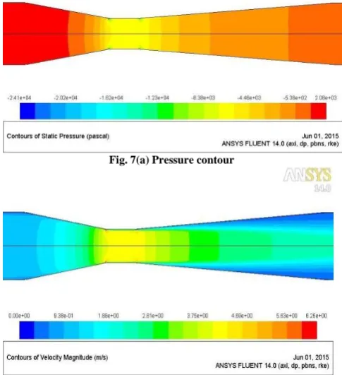
The contours of pressure, velocity and velocity vectors of the venturimeter with 1mm thickness of weld material residuals at the weld joints are as shown in the Fig. 7. In the vector plot it can be clearly observed that at the projections, the flow is separated which affects the pressure reading.
Fig. 7(a) Pressure contour
Fig. 7(b) Velocity contour
0.7 0.8 0.9 1 1.1
0 2 4 6
D
ischa
rg
e
co
ef
fi
ci
en
t
(C
d
)
Weld material residual (mm)
[image:5.595.51.278.367.554.2] [image:5.595.315.558.397.663.2]International Journal of Emerging Technology and Advanced Engineering
Website: www.ijetae.com (ISSN 2250-2459, ISO 9001:2008 Certified Journal, Volume 5, Issue 6, June 2015)
291
Fig. 7(c) Velocity vector
Fig. 7 Pressure and velocity contours with corresponding velocity vector
Thus from the results it is evident that the un-machined interior surface also plays a very crucial role in the value of coefficient of discharge of venturimeter.
B.
Effect of wall roughness on ‘Cd’:The wall roughness height plays an important role on the flow characteristics in the pipe. It is well known that in the case of turbulent flow through pipes, the roughness factor plays an important role on the friction factor and head loss. Thus the performance characteristics of a venturimeter can also be expected to be affected. Hence ISO-5167-1 specifies maximum allowable roughness for different types of venturimeters. It is essential that the surface finish of the flow meter is kept within these limits in order to ensure the accuracy of flow measurement since otherwise the value of actual discharge coefficient would deviate from the standard values. As per ISO-5167-1 the allowable roughness heights at the wall surfaces should be less than 10-4D. Hence, in this present study an attempt has been made to determine the maximum allowable roughness height that can be acceptable for the manufacturing of venturimeters, using computational methods.
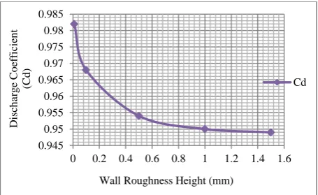
Simulations were carried out for the standard classical venturimeter with the dimensions (D=100mm and =0.5) within the range specified in the ISO standards by incorporating the varying roughness height at the wall. The results obtained from the simulations for different roughness heights at a Reynolds number of 2x10⁵ are tabulated in the Table 4. it is observed that the discharge coefficient reduces with increase in the roughness height at the wall. This can be attributed to the fact that as the wall roughness increases the head losses due to friction increases. Hence, the pressure differential indicated by the flow meter at a given flow rate would increase which in turn results in the reduction of discharge coefficient. It is observed that a wall roughness height of 0.1mm in this pipe (h/D=10-3) results in approximately 2% reduction in the value of discharge coefficient.
TABLE 4
CD VALUE OF VARYING WALL ROUGHNESS HEIGHT
Average Roughness Height (mm)
Pressure Drop (Pa)
Cd
0 7.67x10³ 0.987
0.01 7.773x10³ 0.982
0.1 8.012x10³ 0.968
0.5 8.244x10³ 0.954
1 8.312x10³ 0.950
1.5 8.320x10³ 0.949
Figure 8 shows the reduction in the discharge coefficient with the increase in the wall roughness height. From the analysis it can be concluded that the maximum allowable roughness height (ks/D) should be less than 10
-4 so that the discharge coefficient is not significantly
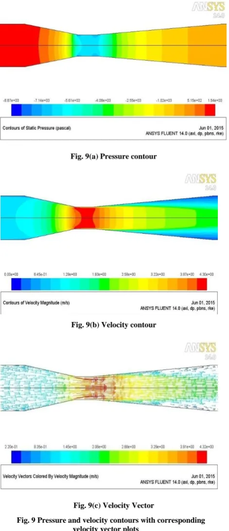
[image:6.595.50.283.154.280.2]affected and the variation is within the specified limits of ISP-5167-1. This conclusion is in agreement with the recommendations given in ISO-5167-1. The present computations also give quantitative estimate of the effect on the value of discharge coefficient when the wall roughness is beyond the allowable limit. It is to be noted that as the meter is kept in the pipe line for longer duration (a number of years), due to ageing and erosion by the continuous fluid flow the surface of the meter may become more and more uneven/rough. Under such circumstances the present results will enable the engineers to estimate the inaccuracies in the flow measurements. The contours of pressure, velocity and velocity vectors of the venturimeter with wall roughness of 0.1mm and Re=2x10⁵ are as shown in the Fig. 9.
Fig.8 Effect of wall roughness on Cd
0.945 0.95 0.955 0.96 0.965 0.97 0.975 0.98 0.985
0 0.2 0.4 0.6 0.8 1 1.2 1.4 1.6
D
isch
ar
g
e
C
o
ef
fi
ci
en
t
(C
d
)
Wall Roughness Height (mm)
[image:6.595.324.547.159.323.2] [image:6.595.318.546.559.698.2]International Journal of Emerging Technology and Advanced Engineering
Website: www.ijetae.com (ISSN 2250-2459, ISO 9001:2008 Certified Journal, Volume 5, Issue 6, June 2015)
292
Fig. 9(a) Pressure contour
Fig. 9(b) Velocity contour
[image:7.595.55.291.140.687.2]Fig. 9(c) Velocity Vector
Fig. 9 Pressure and velocity contours with corresponding velocity vector plots
V. CONCLUSIONS
CFD modeling and simulation was performed to determine if CFD simulations could predict the performance of a venturimeter under non-ISO standard conditions typically encountered in metering the different fluids. The results obtained from CFD were used to study the detailed information on venturimeter flow characteristics that could not be easily measured during experimental testing.
It is observed that the inaccuracies in machining of weld material residuals and wall roughness also affect the actual flow measurements by increasing the differential pressure drop across the two pressure taps if they are beyond certain allowable limits. The present analyses have been able to quantify these limits. From the analysis, it is suggested that the maximum allowable weld imperfection would be h/D<10-3 and the maximum allowable roughness height (ks/D) should be less than 10
-4 so that the discharge coefficient is not significantly
affected. Hence while using the venturimeter; it is necessary to ensure a smooth interior surface so that the accuracy of the flow measurement is not affected.
Thus it is also suggested that such computational models can provide an efficient and accurate method for recalibrating flow meters instead of employing costly and time consuming experimental methods.
REFERENCES
[1] Gordon Stobie, Conoco Phillips, Robert Hart and Steve Svedeman, Southwest Research Institute. Erosion in a Venturi Meter with Laminar and Turbulent Flow and Low Reynolds Number Discharge Coefficient Measurements.
[2] C.L. Hollingshead, M.C. Johnson, S.L. Barfuss, R.E. Spall (2011). Discharge coefficient performance of Venturi, standard concentric orifice plate, V-cone and wedge flow meters at low Reynolds numbers. Journal of Petroleum Science and Engineering. [3] Miller, G., Pinguet, B., Theuveny, B., Mosknes, P., 2009. The
influence of liquid viscosity on multiphase flow meters. TUV NEL, Glasgow, United Kingdom.
[4] Indian standard ISO-5167-1, Measurement of fluid flow by means of pressure differential devices (1991).
[5] P. Hari Vijay, V. Subrahmanyam(2014). CFD simulation on different geometries of venturimeter. International Journal of Latest Trends in Engineering and Technology vol-3.
[6] H K Versteeg and W Malalasekera. An introduction to computational fluid dynamics, the finite volume method (1995). [7] Nikhil Tamhankar, Amar Pandhare, Ashwinkumar Joglekar,