International Journal of Emerging Technology and Advanced Engineering
Website: www.ijetae.com (ISSN 2250-2459, ISO 9001:2008 Certified Journal, Volume 4, Issue 6, June 2014)
906
Influence of Welding Parameters on Nugget Formation in RSW
Process
Shaik Shafee
1, Dr. B. Balu Naik
2, Dr. Sammaiah
3, Dr. Mohd. Mohinoddin
41
Assistant Professor, 4Associate Professor, Department of Mechanical Engineering, M.J. College of Engineering & Technology, Hyderabad-500034, India.
2Principal & Professor, JNTUM, Manthani, Kareem Nagar Dt., A.P.
3
Professor, Department of Mechanical Engineering, Aeronautical Engineering College, Dundigal, R.R. Dt., A.P.
Abstract - In order to study the effect of spot welding parameters such as welding force, welding time and welding current intensity on nugget formation and its size in resistance spot welding process of CR3 low carbon steel sheets using ANSYS commercial software package. A 2D axisymmetric electro-thermo-mechanical finite element (FE) model is developed to simulate the nugget forming process and to predict accurately the weld geometry development in both two and three lap sheets. To improve the accuracy, temperature dependent properties of material are taken into account during the simulation. The FE predicted weld nugget growth and nugget size agree well with the experimental results at the same welding conditions. It was obvious from the results the welding time has minor effect on nugget size in comparison with welding current whereas the electrode force is kept constant.. Overall, the present work indicated that finite element analysis can be very useful as an off-line observation tool to estimate the influence of welding parameters on the welding quality and to predict/improve the welding quality.
Key words - Resistance spot welding, CR3 Low carbon steel, finite element method, Nugget, welding parameters
I. INTRODUCTION
Resistance Spot Welding is one of the oldest welding processes. It can be used on very thin foils or thick sections but is rarely used above 6mm thickness. It is used in a wide range of industries but notable for the assembly of sheet metal steel vehicle bodies. A common example is the mass production of automobiles, where a typical car may contain approximately 5000 spot welds. Spot welding offers a number of advantages over other welding technologies, including high speed, ease of automation and energy efficiency. Cold Rolled Low carbon steel offers importantly the advantages of good formability and low cost. The strength, toughness, and fatigue properties of low carbon steel have proved to be adequate providing a sufficient weld size. It was established that the low carbon steel spot welds exhibiting pull-out or button-type fracture on peeling will result in satisfactory mechanical properties.
Resistance spot welding is a complicated process, which involves interactions of electrical, thermal, mechanical and metallurgical phenomena. The materials to be joined are brought together under pressure by a pair of electrodes. A high electric current passes through the workpieces between the electrodes. Due to contact resistance and Joule heating, a molten weld nugget is formed in the workpieces. The workpieces are joined as solidification of the weld pool occurs. Force is applied before, during and after the application of welding current, to maintain the electric current continuity and to provide the pressure necessary to prevent expulsion.
Some works have already been carried out on the modeling of spot welding process and study of the effect of parameters on nugget size. Nied (1984) introduced an electrically, thermally, and structurally coupled axisymmetric model considering temperature-dependent properties and Joule heating. The displacements and stress distributions of the electrode and workpiece were illustrated. However, temperature dependency of contact resistance was not considered. Gould (1987) measured the nugget growth using a metallographic technique. A one-dimensional thermal model, which accounted for heat of fusion, contact resistance, and convection by qualitatively increasing the effective thermal conductivity in the liquid, was developed for comparisons. The differences between the predicted and measured nugget thicknesses and the nugget growths were suggested to be due to radial heat losses and under estimation of the heat generation at the faying surface.
International Journal of Emerging Technology and Advanced Engineering
Website: www.ijetae.com (ISSN 2250-2459, ISO 9001:2008 Certified Journal, Volume 4, Issue 6, June 2014)
907
In the finite element analysis procedure, the temperature-dependent contact resistance and material properties were taken into account. Nugget growth was presented under various welding conditions.
Feulvarch et al. (2004, 2006) presented a finite element formulation to measure the interface contact properties. It was shown that the calculated nugget appears earlier. It was also noticed that the nugget grows faster across the thickness. Hou et al. (2007) developed a 2D axisymmetric thermo-elastic–plastic FEM model using ANSYS software package. The objective of this study was to investigate the behaviour of the mechanical features during the RSW process. They studied the distribution and change history of the contact pressure at both the faying surface and the electrode–workpiece during welding. The deformation of the weldment and the electrode displacement due to the thermal expansion and contraction were also calculated. They observed that the electrode displacement has a direct correlation with the nugget formation, and suggested utilizing this parameter for quality monitoring and process control in RSW. Rogeon et al. (2008) determined the contact conditions at the interfaces electrode–sheet and sheet–sheet. They measured electrical contact resistances depending to the temperature and under pressure in their work.
Shamsul and Hisyam (2007) studied the RSW of austenitic stainless steel type 304. They found that the nugget size does not influence the hardness distribution. In addition, increasing welding current does not increase the hardness distribution. Lately, Eisazadeh et al. (2010) developed an incremental finite element model for parametric study of nugget size in resistance spot welding process. They used published experimental data to verify their model, and investigated effects of contact resistance and electrode force on nugget size and shape. They found that with increasing electrode force, nugget size reduces due to decreasing contact resistance.
It is well known that nugget size is the key factor that influences the welding quality. American Welding society (AWS), American National Standards Institute (ANSI) and Society of Automotive Engineers (SAE) jointly recommended the size of the spot weld nugget diameter for steel according to the following equation d = 4√ Where ‘d’ and ‘t’ are the nugget diameter and sheet thickness in mm respectively. However to ensure an acceptable weld quality and confidence, understanding the mechanism of heat distribution, and weld formation are one of the key issues to develop an appropriate welding conditions.
Due to a large number of pertinent parameters; such as the geometry and materials of sheet products, electrodes, and dynamic characteristics of process and welding machines, it is therefore a difficult task to manage the time-to market of new products, especially when joining complex geometries and new metal combinations. The development of sheet combinations and optimization of process parameters setting in the industry are strongly dependent on the personal experience of welding engineers, which is often based on a trial-and-error method. This involves a great number of running-in experiments with real welding, destructive tests, and metallographic studies. The advantage of applying numerical modelling for resistance welding processes is obvious, especially for joining complex geometries and novel metal combinations. Recent advanced numerical modelling can be therefore an approach to disclose the internal physical phenomena and a promising predictive tool for an innovative resistance welding process.
In this study, a two-dimensional axisymmetric finite element model has been developed to investigate the distribution of temperature and nugget formation during resistance spot welding as well as to study the effects of welding parameters such as applied current and welding time on the nugget size. The results of finite element analyses are compared with the experimental measurements. The contribution of this work contains following three parts:
1. The entire welding process was viewed as a coupled electrical-thermal-mechanical process. 2. Development of an effective finite element model
to describe the resistance spot welding.
3. Conduct extensive experiments and result data analysis to verify the effectiveness of this finite element model.
II. EXPERIMENTAL PROCEDURE
International Journal of Emerging Technology and Advanced Engineering
Website: www.ijetae.com (ISSN 2250-2459, ISO 9001:2008 Certified Journal, Volume 4, Issue 6, June 2014)
908
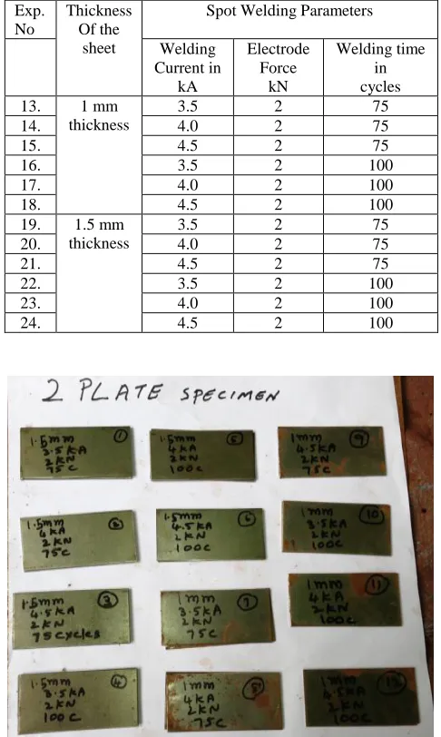
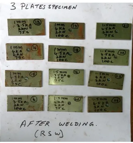
[image:3.612.322.565.169.575.2]Spot welding was performed using a calibrated 15 kVA AC pedestal type resistance spot welding machine operating at 50 Hz, controlled by a Programmable Logic Controller (PLC). Welding was conducted using a 30◦ truncated cone RWMA group A, class 2 electrode with a 7 mm face diameter with 2kN electrode force. To investigate the effect of welding time and current on nugget size, series of test-specimens of the same material were welded, fixing one parameter and varying the other for both two and three lap sheets as per the details in table 2and table 3.The arrangement of spot weld coupons before and after spot welding of both two lap sheets and three lap sheets are shown in figure1a, 1b and 2a and 2b.
TABLE 1
CHEMICAL COMPOSITION (IS 513:2008)
TABLE 2
RSW PARAMETERS USED FOR INVESTIGATING THEIR EFFECT ON NUGGET SIZE FOR TWO LAP SHEETS
Exp. No
Thickness Of the
sheet
Spot Welding Parameters
Welding Current in
kA
Electrode Force
kN
Welding time in cycles
1. 1 mm
thickness
3.5 2 75
2. 4.0 2 75
3. 4.5 2 75
4. 3.5 2 100
5. 4.0 2 100
6. 4.5 2 100
7. 1.5 mm thickness
3.5 2 75
8. 4.0 2 75
9. 4.5 2 75
10. 3.5 2 100
11. 4.0 2 100
12. 4.5 2 100
TABLE 3
RSW PARAMETERS USED FOR INVESTIGATING THEIR EFFECT ON NUGGET SIZE FOR THREE LAP SHEETS
Exp. No
Thickness Of the
sheet
Spot Welding Parameters
Welding Current in
kA
Electrode Force
kN
Welding time in cycles 13. 1 mm
thickness
3.5 2 75
14. 4.0 2 75
15. 4.5 2 75
16. 3.5 2 100
17. 4.0 2 100
18. 4.5 2 100
19. 1.5 mm thickness
3.5 2 75
20. 4.0 2 75
21. 4.5 2 75
22. 3.5 2 100
23. 4.0 2 100
24. 4.5 2 100
Fig.1a Two sheets spot weld coupons (specimens)
S. No.
Designation
Maximum Percentage of alloying elements
Carbon Manganese Sulphur Phosphorus
[image:3.612.43.300.313.371.2]International Journal of Emerging Technology and Advanced Engineering
Website: www.ijetae.com (ISSN 2250-2459, ISO 9001:2008 Certified Journal, Volume 4, Issue 6, June 2014)
[image:4.612.332.558.131.375.2]909
Fig. 1b Two sheets spot weld coupons (specimens) after welding
Fig.2a. Three sheets spot weld coupons (specimens)
Fig. 2b Three sheets spot weld coupons (specimens) after welding
III. SIMULATION OF CR3LOW CARBON STEEL-RSWVIA
FEM
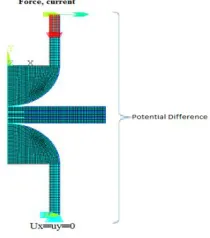
The objective of this project work is to develop a multi-coupled method to analyse the thermal and mechanical behaviours of RSW process, reduce the computing time with the minimum loss of accuracy and get more adequate information of the process, improve the quality monitoring and process control of RSW. A practical model of spot welding for two and three pieces of sheets used. Current (I) and force (F) applied to the electrodes are electrical load and mechanical load, respectively. The thermal boundary condition, electrical boundary condition (current boundary and potential) and displacement boundary conditions are also shown in these figures 3 & 4. As simply described in the above sections, the spot welding process couples electrical field, thermal field and mechanical field including the contact states at the interfaces between worksheets and electrodes.
IV. GOVERNING EQUATIONS
[image:4.612.58.280.408.607.2]International Journal of Emerging Technology and Advanced Engineering
Website: www.ijetae.com (ISSN 2250-2459, ISO 9001:2008 Certified Journal, Volume 4, Issue 6, June 2014)
910
t T ρC = v q + r T r k + z T k z + r T k r (1)Where ρ, C and k are density, specific heat and thermal conductivity respectively. All the material properties are considered to be temperature dependent. The term qv refers to the rate of internal heat generation per unit volume.
The thermal boundary conditions can be decomposed from the nonlinear isotropic Fourier heat flux constitutive relation:
q = (2) On the boundary surface, there is
q = n T (3)
Where ‘q’ is the heat flux through the boundary surface; ‘n’ is the outward normal to the surface.
The governing equation of the electrical analysis is
0 z φ e C z + r φ r e C + r φ e C
r
(4)
Where, Ce is the electrical conductivity; ф is the electrical potential.
The coupled thermal electrical problem is solved by the following matrix equation:
[[, , -- , -, -]] {{ ̇}
{ ̇}} [
, - ,
-, - , - ]{* +* +} {* +* +} (5)
Where , - is the thermal specific heat matrix; , - the thermal conductivity matrix; , - the electric coefficient matrix; * + temperature vector; * + the electric potential vector; {Q} the heat flow vector; and {I} is the current vector.
For the structural analysis, the stress equilibrium equation is given by
* + ( ) (6)
The constructive equation of the material based on the thermo-elastic-plastic theory is given by
Where σ is the stress; b is the body force, r is the coordinate vector.
* + , - * + * + (7)
* + , - .* + , - * +/ (8)
Where {σ} is the stress vector; [D] is the elastic-plastic matrix; {ε} is the strain vector; [De] is the elastic matrix; and {α} is the coefficient of thermal expansion.
V. MODELING AND PARAMETERS
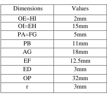
Figure 3 & 4 illustrates the 2-dimensional axisymmetric FEA model of RSW process built in ANSYS program, where X and Y represent the faying surface and the axisymmetric axis respectively. Its corresponding dimensions are tabulated in Table 4. Since the model is also mirror symmetric about the faying surface, only the values of the upper half of the model are listed.
2-D axisymmetric models of two- as well as three-sheet joining with the application of round-face electrodes are constructed. Both electrical-thermal and mechanical contact elements are specially treated at the electrode-to-sheet and electrode-to-sheet-to-electrode-to-sheet interface. The imposed boundary conditions and representative mesh model can be found in Fig.4.
[image:5.612.357.530.461.613.2]In each analysis, the model is meshed using contact elements as shown in fig.4a&b the solid element is employed to simulate the coupled interaction between the sheets and electrodes.
TABLE 4
Dimensions Values
OE=HI 2mm
OI=EH 15mm
PA=FG 5mm
PB 11mm
AG 18mm
EF 12.5mm
ED 3mm
OP 32mm
International Journal of Emerging Technology and Advanced Engineering
Website: www.ijetae.com (ISSN 2250-2459, ISO 9001:2008 Certified Journal, Volume 4, Issue 6, June 2014)
911
(A)
(B)
[image:6.612.74.270.136.697.2]Fig. 3 A & B: The Computational Domain And Boundary Conditions
Fig. 4a The FEA model for two lap sheets
Fig. 4b The FEA model for three lap sheets
In order to correctly couple and transfer the data the model must have identical mesh both in the electrical – thermal analysis and in the thermo-elastic and plastic analysis. Whereas the element types are different or have different degree of freedom options, as shown in Table 5.
TABLE 5
ELEMENT TYPES AND DEGREE OF FREEDOM OPTIONS
Analysis
Electrical-Thermal
Thermo-Elastic-Plastic
Solid PLANE 67 PLANE 42
Contact element type CONTACT17 1/TARGET
169
CONTACT171/TARGE T 169
Degree of freedom (for contact element)
TEMP, VOLT
UX, UY
VI. INTERFACE ELEMENTS
[image:6.612.397.502.146.265.2]International Journal of Emerging Technology and Advanced Engineering
Website: www.ijetae.com (ISSN 2250-2459, ISO 9001:2008 Certified Journal, Volume 4, Issue 6, June 2014)
912
The material properties of interface contact elements used for the analysis of the electrical field, thermal field and mechanical field are independent from worksheets and electrodes. Therefore, the contact resistance can also be considered if it is known. The formulation of the interface element has no much difference from the ordinary element except the material properties and their changes with the contact states. Therefore, it is relatively simple and reliable to deal with the electrical–thermal–mechanical contact between two faces for the spot welding process simulation. Prior to welding, the electrical initial conditions are set equal to zero, while the temperature of entire structure is maintained at temperature of 25°C. During the welding cycle, the welding current is applied at the top of the upper electrode and zero potential is imposed at the bottom surface of the lower electrode. Consequently, the current flows from the upper electrode, passes through work piece and terminates at the bottom annular section of the lower electrode. Both force and current are modelled from practical welding signals and defined as a time-dependent function.
Fig.5 Contact elements
(A)
(B)
Fig.6 Two lap sheets A & B Nugget formation and Temperature field
International Journal of Emerging Technology and Advanced Engineering
Website: www.ijetae.com (ISSN 2250-2459, ISO 9001:2008 Certified Journal, Volume 4, Issue 6, June 2014)
913
VII. MECHANICAL BOUNDARY CONDITIONS
Uniform load was applied at the top of the copper electrode during welding and holding cycle. The electrode was removed at the end of the holding cycle. At the faying surface between the electrode and the workpiece, a contact 171 element was used. At the faying surface between workpiece and workpiece, the vertical displacement of the part of faying surface under electrode was set to zero, and a subroutine program was used to determine if the other part of faying surface is under contact or not. If some nodes are under contact and are under pressure stress, a zero vertical displacement was applied here.
VIII. WELDING PARAMETERS AND MATERIAL PROPERTIES
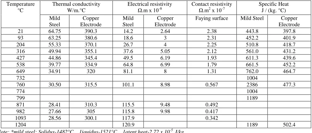
[image:8.612.53.559.307.523.2]The welding parameters used in this analysis are: welding current 50 Hz sine wave AC current of 3.5kA, 4kA and 4.5kA;weld time, 75 cycles (1.5 Sec): 100 cycles ( 2 Sec ) electrode force 2000 N: hold time 3 cycles (0.06 Sec). The thermal, electrical and mechanical properties of electrode and work piece are given in Table 6 and Table 7. Because the materials are subjected to a wide range of temperatures, most of these properties are considered as temperature dependent.
TABLE 6
THERMAL AND ELECTRICAL PROPERTIES OF MATERIALS*
Temperature °C
Thermal conductivity W/m.°C
Electrical resistivity Ω.m х 10-8
Contact resistivity Ω.m2
х 10-7
Specific Heat J / (kg. °C) Mild
Steel
Copper Electrode
Mild Steel
Copper Electrode
Faying surface Mild Steel Copper Electrode
21 64.75 390.3 14.2 2.64 2.38 443.8 397.8
93 63.25 380.6 18.6 3 2.31 452.2 401.9
204 55.33 370.1 26.7 4 2.25 510.8 418.7
316 49.94 355.1 37.6 5.05 2.12 561.0 431.2
427 44.86 345.4 49.5 6.19 1.93 611.3 439.6
538 39.77 334.9 64.8 6.99 1.79 661.5 452.2
649 34.91 320 81.1 8 1.31 762.0 464.7
732 1004
760 30.50 315.5 101.1 8.98 0.567 2386 477.3
774 1004
799 1189
871 28.41 310.3 115.5 9.48 0.492
982 27.66 305 115.8 9.98 0.417
1093 28.56 300.1 117.9 0.342
1204 120.9 1189 502.4
Note: *mild steel: Solidus-1482°C.1iquidus-1521°C.1atent heat-2.72 x 10⁻⁵ J/kg
TABLE 7
MECHANICAL PROPERTIES OF MATERIALS
Temp °C
Young’s Modulus G Pa
Yield stress M Pa
Poisson’s ratio Coefficient of thermal expansion l °C
Density Kg/m3 Mild
Steel
Copper Electrode
Mild Steel
Copper Electrode
Mild Steel
Copper Electrode
Mild Steel
Copper Electrode
Mild Steel
Copper Electrode
21 206 124 248 10.98 16.56
93 196 105 238 11.52 16.74
204 194 93 224 12.24 17.1
316 316 82 200 12.96 17.46
427 169 55 172 83 0.3 0.32 13.5 17.82 7800 8900
538 117 38 145 14.04 18.36
649 55 25 76 14.58 18.54
760 16 14.04 18.9
871 14 13.5 19.26
International Journal of Emerging Technology and Advanced Engineering
Website: www.ijetae.com (ISSN 2250-2459, ISO 9001:2008 Certified Journal, Volume 4, Issue 6, June 2014)
914
13 14 15 16 17 18
3.2 3.4 3.6 3.8 4.0 4.2 4.4 4.6
1.0 mm thickness three lap sheets
EXPERIMENT NO. NU G G ET D IAM ETER ( m m )
B = EXPERIMENTAL UPPER NUGGET DIAMETER C = EXPERIMENTAL LOWER NUGGET DIAMETER
D = SIMULATION UPPER NUGGET DIAMETER
E = SIMULATION LOWER NUGGET DIAMETER
19 20 21 22 23 24
3.2 3.3 3.4 3.5 3.6 3.7 3.8 3.9 4.0 4.1 4.2 4.3 4.4 4.5 4.6
1.5 mm thickness three lap sheets
EXPERIMENT NO. N U G G ET D IAM ET ER ( m m )
B = EXPERIMENTAL UPPER NUGGET DIAMETER C = EXPERIMENTAL LOWER NUGGET DIAMETER
D = SIMULATION UPPER NUGGET DIAMETER
E = SIMULATION LOWER NUGGET DIAMETER
1 2 3 4 5 6
3.6 3.8 4.0 4.2 4.4 4.6 4.8
1 mm thickness two lap sheets
B= EXPERIMENTAL VALUES OF NUGGET DIAMETER C= SIMULATED VALUES OF NUGGET DIAMETER
N U G G E T D IA M E TE R (m m ) EXPERIMENT NO.
7 8 9 10 11 12
3.6 3.7 3.8 3.9 4.0 4.1 4.2 4.3 4.4 4.5 4.6
1.5 mm thickness two lap sheets
B= EXPERIMENTAL VALUES OF NUGGET DIAMETER
C= SIMULATED VALUES OF NUGGET DIAMETER
N U G G E T D IA M E TE R (m m ) EXPERIMENT NO.
IX. RESULTS AND DISCUSSIONS
International Journal of Emerging Technology and Advanced Engineering
Website: www.ijetae.com (ISSN 2250-2459, ISO 9001:2008 Certified Journal, Volume 4, Issue 6, June 2014)
915
Fig.7 Three lap sheets Nugget formation and Temperature field
X. CONCLUSIONS
A multi coupled electro-thermal and thermo-elastic-plastic analysis is developed and carried out on the transient thermal and mechanical behaviors of the RSW process. Based on the ANSYS software, this multi coupled method can efficiently provide sufficient details of the RSW and benefit to the quality monitoring and process control of RSW. Finite element analysis can be very useful as an off-line observation tool to estimate the influence of welding parameters on the welding quality and to predict/improve the weld geometry.
REFERENCES
[1] ANSI/AWS/SAE/D8. 9-97, 1997. Recommended Practices for Test Methods and Evaluation the Resistance Spot Welding Behavior of Automotive Sheet Steels Materials. American Welding Society, Miami, FL, USA.
[2] ANSI/AWS/Sae/C1.1, 2000. Recommended Practice for Resistance Welding. American Welding Society, Miami, FL, USA.
[3] ASTM E 340-00, Reapproved 2006. Standard Test Method for Macroetching Metals and Alloys. ASTM International, USA. [4] Cho, H.S., Cho, Y.J., 1989. A study of thermal behavior in resistance
spot welds. Welding J. 67, 236–244.
[5] Eisazadeh, H., Hamedi, M., Halvaee, A., 2010. New parametric study of nugget size in resistance spot welding process using finite element method. Mater. Des. J. 31, 149–157.
[6] Feulvarch, E., Robin, V., Bergheau, J.M., 2004. Resistance spot welding simulation: a general finite element formulation of electrothermal contact conditions. J. Mater. Process. Technol. 153– 154, 436–441.
[7] Feulvarch, E., Robin, V., Bergheau, J.M., 2006. Resistance spot welding process: experimental and numerical modeling of weld growth mechanisms with consideration of contact conditions. Numer. Heat Trans. Part A 49, 345–367.
[8] Gould, J.E., 1987. An examination of nugget development during spot welding, using both experimental and analytical techniques. Welding J. 66, 1–10.
[9] Hou, Z., Kim, I., Wang, Y., Li, C., Chen, C.J., 2007. Finite element analysis for the mechanical features of resistance spot welding process. J. Mater. Process. Technol. 180, 160–165.
[10] Na, S.J., Park, S.W., 1996. A theoretical study on electrical and thermal response in resistance spot welding. Welding J. 75, 233– 241.
[11] Nied, H.A., 1984. The finite element modeling of the resistance spot welding process. Welding J. 63, 123–132.
[12] Rogeon, P., Carre, P., Costa, J., Sibilia, G., Saindrenan, G., 2008. Characterization of electrical contact conditions in spot welding assemblies. J. Mater. Process. Technol. 195, 117–124.
[13] Shamsul, J.B., Hisyam, M.M., 2007. Study of spot welding of austenitic stainless steel type 304. J. Appl. Sci. Res. 3, 1494–1499. [14] Sun, M.A.T., 2003. Fundamental study of contact resistance
behavior in RSW aluminum. The Ohio State University, Graduate School Ohio, p. 314.
[15] Tsai, C.L., Dai, W.L., Dickinson, D.W., Papritan, J.C., 1991. Analysis and development of real-time control methodology in resistance spot welding. Welding J. 69, 339–351.
[16] Tsai, C.L., Jammel, O.A., Papritan, J.C., Dickinson, D.W., 1992. Modeling of resistance spot weld nugget growth. Welding J. 70, 47– 54.
[17] Khan, J.A.; Xu, L.; and Chao, Y.J. 1999. Prediction of nugget development during resistance spot welding using coupled thermal-electrical-mechanical model. Science and technology of welding and joining. Vol. 4, No.4: 201 to 207.