1437
A Novel Method For Enhancing Gain Of Microstrip
Antenna
Pratibhadevi Tapashetti , Rakesh Agarwal, Prashant Chaturvedi
Abstract: Microstrip antennas are very popular in recent decades due to its small size, low cost, light weight, and easy fabrication. This antenna has many useful characteristics like thin profile, both linear and circular polarization, dual frequency operation possible, and with any shape. It has several applications in wireless communication, in telemedicine, in mobile communication. iHowever, the itypes of applicationsi of microstrip antennas are restrictedi by the antennasi inherently low gain and narrowi bandwidthi. Accordingly, iincreasing the gain and bandwidth of the microstrip antenna has been a main goali of researchi in the fieldi. Aim of this paper is to increase gain of microstrip antenna. So, made some changes in different parameters of microstrip antenna like patch length, width or substrate size and gain and efficiency are observed.
Keywords: Microstrip, Antenna, Gain, Efficiency, patch
————————————————————
.
1
INTRODUCTION
Now a day’s wireless communication has many applications in different areas such as satellite communication, mobile communication, WLAN and Remote sensing, etc. Such systems require better performance, low cost, speed and reduced size, etc. For fulfillment of such criteria, antennas are designed of differenti shapesi and sizesi suited for differenti applicationsi. Micro-strip Antennas, earlier used only for defensei and commerciali applicationsi, are replacingi many conventionali antennasi [1]. Howeveri, the typesi of applicationsi of microstrip antennas are irestricted by the iantennas inherentlyi low gain and narrowi bandwidth (BW). Accordinglyi, increasingi the gain and bandwidth of thei microstrip antenna has been a iprimary igoal of iresearch in the ifield. Thusi, severali advantagesi of microstrip antennas led to the idesign of iseveral configurationsi for ivarious applicationsi. Large gaini and small size antenna provide high efficiency and good reliability [2]. Microstrip antenna is fabricated on PCB. It is used at microwave frequency. Its fabrication is easy due to PCB techniques. They are very popular in recent decades due to small size and easy fabrication. By selecting different patch length and patch width output parameters are observed for microstrip patch antenna [3]. Microstrip antenna consists of dielectric slab, one side consists of radiating patch and other side act as ground plane. Both linear and circular polarizations are used for microstrip antenna. Conducting patch made by copper or gold and has any shape like circular, rectangular, elliptical, etc, but the rectangular and circular patches are most popular due to easy fabrication, and their useful characteristics [4]. Microstrip antennas have different types, such as microstrip dipole, imicrostrip ipatch, microstripi travellingi wavei and microstripi slot [5]. Characteristics of microstrip antenna are thin profile, easy fabrication, both linear and circular polarization, dual frequency operation possible, and with any shape [6].
It has several applications like in wireless communications, in telemedicine’s, in mobile communications, etc. The performance of any antenna can be determined by certain parameters, such as, gain, bandwidth, half power beam width (HPBW), antenna efficiency, side lobe level (SLL), cross polar level (CPL), standing wave ratio (SWR), and return loss (RL). Also, to understand the performance of a given antenna in RF range, one should have thorough knowledge of Smith Chart and Scattering parameters [7]. Antenna gain is defined as ratio of radiated power in specific direction to its power in isotropic direction. Antenna efficiency considers all losses such as dielectric losses, conduction losses, and reflection losses [8]. In this paper, gain enhancement obtained using slotting techniques. This technique is simple than other techniques because there is freedom to add desired slot. In this, EBG structure is used which reduces surface wave effect and obtain improvement in gain [9].iAntenna bandwidthi is describedi based on gaini, Impedancei or VSWRi. Heighti of the substratei and the iwidthi of the patchi playi an importanti role for ithe maximizingi of the radiationi efficiencyi and the ibandwidth of the imicrostrip antennai. If higher is the height (1.5 mm) of substrate then more volume of fringing effect occurred, and its output is betteri returni lossi and bandwidthi. If Heighti is above 1.5 mm then reduction in antenna parameters are obtained [10]. Usingi photonici crystali as substratei it is onei of the types to increase igain. For good iantenna iperformance, select thicki substrate whosei idielectric iconstant is in the ilower endi of irange, it produces betteri efficiencyi and highi igain [11].
2
PARAMETRIC
STUDY
The gain of the antenna is closely related to the directivity, it is a measure that considers the efficiency of the antenna as well as its direction capabilities. Antenna gain is defined as ratio of radiated power in specific direction to its power in isotropic direction. Antenna efficiency is a ratio of total radiated power to input power at feed point.
Gain = E.D (1) D= Directivity.
In this paper, gain variation is obtained due to change in different parameters like patch size, patch length, patch width, feed position, ground plane size and substrate air gap. “Fig. 1” shows single microstrip antenna with top side and bottom side of substrate. Thei structurei is optimizedi to operatei overi
_______________ _
• Dr. Pratibhadevi Tapashetti Professor in Department of Electronics & Communication Engineering at Holy Mary Institute of Technology &Science,Telengana,India,PH-7389393612, E-mail:[email protected]
• Rakesh Agarwal Associate Professor in Department of Electronics & Communication Engineering at L.N.C.T Bhopal, India PH-9425648182. E-mail: [email protected]. • Prashant Chaturvedi Assistant Professor in Department of
Electronics & Communication Engineering at L.N.C.T Bhopal, India, PH-8109528276.
5.725- 6.4 GHzi. The structures is simulated using IE3D software.
(a)
(b)
(c)
(d)
(e)
Fig. 1 (a) Single microstrip antenna (b) Top side of substrate (c) Bottom side of substrate (d) Bottom view (e) Front view
Now we cosider different parameters of microstrip ntenna for gain enhancement.
A Effect of changei in RISi Squarei patchi sizei
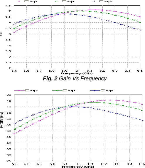
The isuspended MSAi with RISi is optimizedi andi its dimensionsi are MSAi patchi of 12.8 mm x14.5 mmi, ifeed positioni at 4.7 mmi alongi width edgesi on x axisi, iground planei of 38 mm x 38 mmi and a Reactivei Impedancei Surfacei of 5x5 squarei patchesi of sizei and spacingi 4 mm. The ioptimized antennai structurei providesi an iimpedance bandwidthi of 679 MHzi, maximumi efficiencyi upi to 73.5%. Three different RIS square patch size are used 3 mm (pink color), 4 mm (green color) and 5 mm (blue color). “Fig. 2 and 3” shows the imagnitude of the igain, iefficiency and iits ivariation overi the operatingi frequencyi increases slightlyi with decreasei in RIS squarei patchi sizei.
Fig. 2 Gain Vs Frequency
1439
Effect of Microstrip Patch Length
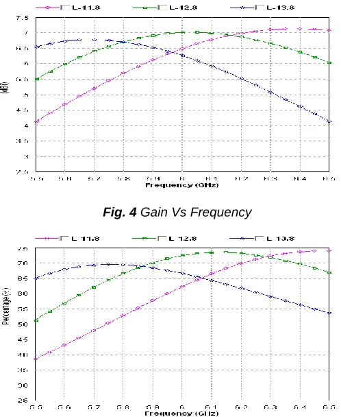
Consider three patch lengths 11.8 mm (pink color), 12.8 mm (green color), 13.8 mm (blue color). The gain and efficiency increase slightly with decrease in patch length and vice versa, as shown in “Fig. 4 and 5”.
Fig. 4 Gain Vs Frequency
Fig. 5 Efficiency Vs Frequency
As shown in above fig. 4 and fig. 5, when patch length is 11.8 mm gain is 6.5 dB and efficiency is 63%, if patch length is 13.8 mm then gain is 6.3 dB and efficiency is 65%. So, patch length should be minimum for betterment of gain and efficiency.
Effect of microstrip patch width
Consider three patch widths 13.8 mm (pink color), 14.8 mm (green color) and 15.8 mm (blue color). “Fig. 6 and Fig. 7” shows the gain and efficiency values observed almost same for increase or decrease in patch width.
Fig. 6 Gain Vs Frequency
Fig. 7 Efficiency Vs Frequency
Effect of change in feed position
The optimized suspended MSA with RIS has a feed position on x axis at 3.5 mm, 4.5 mm and 5.5 mm. The change in feed position changes the resonant frequency of the antenna, and the magnitudes of gain decreases slightly with shifting feed position. When feed position on x axis at 3.5 mm, gain is 6.7 dB and if it is 5.5 mm then gain is 6.8 dB, as shown in “Fig. 8”.
Fig. 8 Gain Vs Frequency
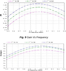
Effect of Ground Plane Size
Fig. 9 Gain Vs Frequency
Fig. 10 Efficiency Vs Frequency
Effect of Substrate air gap
The ioptimized isuspended MSA with iRIS has a substrate air gap of height 0.5 mmi, 1.0 mm iand 1.5 mm. The change in height of substrate air gap of suspended MSA changes the resonanti frequencyi of the antenna. The igain, bandwidth and efficiency decrease significantly by decreasing substrate air gap height, as shown in “Fig. 11 and Fig. 12”.
Fig. 11 Gain Vs Frequency
Fig. 12 Efficiency Vs Frequency
As shown in Fig. 11 and Fig. 12, when air gap is 0.5 mm, then gain and efficiency are 6.5 dB and 65%, if air gap size is 1.5 mm, then gain and efficiency are 7 dB and 75%. Keep substrate air gap maximum for maximum gain and efficiency. Gain and efficiency can vary by changing different parameters of microstrip antenna.
3
RESULT
Following table shows gain and efficiency of a Microstrip Antenna by considering all the above parameters.
TABLEI.OUTPUT GAIN AND EFFICIENCY BY CONSIDERING
DIFFERENT PARAMETERS.
Sr
No Parameter Size
Gain (dB)
Efficiency (%)
1 RIS Square
patch size
3 mm 7 72
5 mm 6.7 70
2 Patch Length
11.8 mm 6.5 63
13.8 mm 6.3 65
3 Patch width 13.8 mm 7 71
15.8 mm 7 72
4 Ground Plane
Size
34 mm 6.5 66
42 mm 7.35 75
5 Substrate air gap
0.5 mm 6.5 65
1. 5 mm 7 75
4
CONCLUSION
Microstrip antenna is widely used because of its different advantages but it has some disadvantages like low gain. Gain is an important parameter of microstrip antenna, so the gain of antenna must be increased for different applications. In this paper, gain enhancement is obtained by changing some parameters of microstrip antenna considering patch size, patch length, patch width, feed position, ground plane size and substrate air gap, etc. Gain and efficiency can vary by changing these parameters of microstrip antenna. So, by considering maximum ground plane size and maximum substrate air gap and minimum patch size, maximum gain and efficiency for Microstrip Antenna are obtained. Gain and efficiency can vary by changing different parameters of microstrip antenna.
5
REFERENCES
[1] R. D. Javor, X.D. Wu, and K. Chang, “Design and performance of a microstrip reflectarray antenna”, IEEE Transactions on Antennas and Propagation, Vol. AP-43, no.9, pp. 932-939, Sept 1995.
[2] Preeti Sharma, Shubham Gupta “Bandwidth and gain enhancement in microstrip antenna array for 8GHz frequency applications”IEEE Xplore 2014 Students Conference on Engineering and Systems, Allahabad, pp. 1-6, 21 August 2014.
1441 Antenna for WLAN”, Indian Journal of Radio and
Space Physics, Vol. 40, October 2011, pp. 282-286. [4] D. M. Pozar and D. H. Schaubert, Microstrip
Antennas: The Analysis and Design of Microstrip Antennas and Arrays, John Wiley and sons Inc. USA, 1995.
[5] D. M. Pozar, S. D. Targonski and H. Syrigos, “Design of millimeter wave microstrip reflectarrays", IEEE Transactions on Antennas and Propagation. vol. AP-45, no.2, pp.287-295, Feb. 1997.
[6] P.N. Chine and Girish Kumar, “Three dimensional, efficient, directive microstrip antenna arrays,” IEEE International symposium on Antenna and Propagation, Washington DC., July 2005.
[7] Constantine A. Balanis, Antenna Theory and Design, 3rd Edition, John Wiley and sons Inc. USA, May 2005.
[8] Ramya Rajan Choudhary, “A iNetwork Overviewi of Massivei MIMO for 5G Wirelessi Cellulari: Systemi
Modeli and Potentialsi” iInternational Journali of Engineeringi Researchi and Generali Sciencei
Volume 2, iIssue 4, June-July 2014.
[9] R. Dhanalakshmi, K. Santosh and R. Srinivas, “Gain enhancement of slotted microstrip patch antenna using EBG”, The International Journal of Engineering and Science (IJES), vol. 3, issue no. 6, pp. 53-57, June 2014.
[10]R. Mishra, P. Kuchhal, A. Kumar, “Effecti of Heighti of the iSubstrate and iWidth of the iPatch on the
iPerformance Characteristicsi ofi Microstrip iAntenna” Internationali Journali of Electricali and iComputer Engineeringi (IJECE) Vol. 5, No. 6, pp. 1441~1445, December 2015.
[11]M. T. Ali, H. Jaafar, S. Subahir and A. L. Yusof, "Gainiienhancement of air substratesi at 5.8GHz for microstripi antennai arrayi," IEEE 2012 Asia-Pacifici