PNEUMATIC VARIABLE
STIFFNESS SOFT ROBOT END
EFFECTORS
Loai Ali Talib Al Abeach
Autonomous Systems and Robotics Centre
School of Computing, Science & Engineering
University of Salford, Salford, UK
Submitted in Partial Fulfilment of the Requirements
of the Degree of Doctor of Philosophy
Publications
1- A journal paper is published in the Soft Robotics journal (current impact factor is 8.649).
Al Abeach Loai A.T., Nefti-Meziani Samia, and Davis Steve. Soft Robotics. June
2017. Design of a variable stiffness soft dexterous gripper. Ahead of print. https://doi.org/10.1089/soro.2016.0044
2- A journal paper is submitted to the journal of Bionic Engineering.
Al Abeach, Loai A. T., Nefti-Meziani, Samia, & Davis, Steve (2017). “A Variable Stiffness Soft Gripper Using Granular Jamming”. Bionic Engineering.
3- A poster in the 1st UK Manipulation Workshop, Birmingham.
Al Abeach, Loai A. T., Davis, Steven, & Nefti-Meziani, Samia. (2016). “A Computer Controlled Soft Robot Manipulator for Safe Human-Robot Interaction”. 1st UK Manipulation Workshop, Birmingham.
4- A poster in the College of Science and Technology Research and Innovation Showcase 2015, University of Salford.
iii
Contents
Publications ... ii
Contents ... iii
List of Figures ... vii
Acknowledgements ... xii
Abbreviations ... xiii
Abstract ... xiv
Chapter One ... 1
1 General Introduction ... 1
1.1 Introduction ... 1
1.2 Aim and Objectives ... 3
1.3 Research Methodology ... 3
1.4 List of Contributions ... 5
1.5 Organisation of Thesis ... 5
Chapter Two ... 8
2 Literature Review ... 8
2.1 Introduction ... 8
2.2 Actuators with an Elastic Element ... 9
2.2.1 Series Elastic Actuator ... 10
2.2.2 Hydro-Elastic Actuator ... 11
2.2.3 Series Elastic Actuator for a Biomimetic Walking Robot ... 11
2.2.4 Compact Soft Actuator ... 12
2.2.5 Compact Rotary Series Elastic Actuator ... 13
2.3 Variable Stiffness Actuators ... 14
2.3.1 Selective Compliant Actuator ... 15
2.3.2 Safe and Fast Physical Human-Robot Interaction Actuator ... 16
2.3.3 Variable Stiffness Actuator for Safe and Performing Robots Interacting with Humans ... 16
iv 2.3.5 Mechanical Adjustable Compliance and Controllable Equilibrium
Position Actuator 2.0 ... 18
2.3.6 Variable Stiffness Based on Adaptable Pivot Point ... 19
2.3.7 Variable Stiffness Joint by Granular Jamming ... 20
2.4 Pneumatic Muscle Actuator ... 21
2.4.1 Pneumatic Muscle Actuators Structure ... 21
2.4.2 Pneumatic Muscle Actuator Operation ... 22
2.4.3 Pneumatic Muscle Actuator Construction ... 23
2.4.4 Pneumatic Muscle Actuator Applications ... 23
2.4.5 Mathematical Models for Pneumatic Muscle Actuators ... 24
2.4.6 Methods of Controlling Pneumatic Muscle Actuators ... 24
2.5 Continuum Arms ... 26
2.5.1 Intrinsic Planar Continuum Arm ... 27
2.5.2 Intrinsic Spatial Continuum Arm ... 28
2.5.3 Extrinsic Continuum Arm ... 29
2.5.4 Hybrid Continuum Arm ... 30
2.6 Pneumatic Continuum Arms ... 30
2.6.1 Extensor Continuum Soft Robot Arm ... 31
2.6.2 Contractor Continuum Soft Robot Arm ... 32
2.6.3 Air-Octor Continuum Soft Robot Arm ... 34
2.6.4 Single Latex Rubber Tube Continuum Soft Robot Arm ... 36
2.6.5 Granular Jamming Continuum Soft Robot Arm ... 37
2.6.6 Mathematical Models for the Pneumatic Continuum Arms ... 38
2.7 Soft Robot End-Effectors ... 39
2.7.1 Whole Arm Grasping Using Continuum Soft Robot ... 40
2.7.2 Multi-fingered Soft Robot End Effectors ... 46
2.7.3 Granular Jamming Universal Grippers ... 55
2.8 Conclusion ... 57
Chapter Three ... 61
3 Actuator Modelling and Variable Stiffness Investigations ... 61
3.1 Introduction ... 61
v
3.2.1 Force/Displacement Characteristics of the Contractor PMA ... 64
3.2.2 Pressure/Displacement Characteristics of the Contractor PMA ... 73
3.3 Extensor Pneumatic Muscle Actuator Modelling ... 75
3.3.1 Force/Displacement Characteristics of the Extensor PMA ... 76
3.3.2 Pressure/Displacement Characteristics of the Extensor PMA ... 79
3.4 Variable Stiffness Characteristics Investigation for the Pneumatic Muscle Actuators ... 81
3.5 Granular Jamming Variable Stiffness Characteristics Investigation ... 87
3.6 Conclusion ... 92
Chapter Four ... 94
4 Design and Implementing, Variable Stiffness, Soft Robot End-Effectors ... 94
4.1 Introduction ... 94
4.2 Continuum Actuator ... 95
4.3 Continuum Soft Robot End Effector’s Basic Prototypes ... 97
4.4 Design and Implementation of Continuum Soft Robot End Effector ... 100
4.5 The Finger Kinematics in the Continuum Soft Robot End Effector ... 112
4.6 Control and Performance Evaluation of the Continuum, Variable Stiffness, Soft Robot End Effector ... 114
4.7 Design and Implementation of Continuum Soft Robot End Effector with Granular Jamming ... 122
4.8 Control and Performance Evaluation of Variable Stiffness Granular Jamming End Effector ... 123
4.9 Conclusion ... 132
Chapter Five ... 135
5 Controlling the Operation of Pneumatic Variable Stiffness Soft Robot Manipulator and End Effectors ... 135
5.1 Introduction ... 135
5.2 Design and Implementation of a Pneumatic Four-Fingered Continuum Variable Stiffness Soft Robot End Effector ... 137
5.3 Position Control for the Pneumatic Four-Fingered Continuum Variable Stiffness Soft Robot End Effector ... 143
vi
5.5 Design and Implementation of Pneumatic Continuum Soft Robot Arm .... 148
5.6 Pressure Control of Pneumatic Continuum Soft Robot Arm ... 151
5.7 Simplified Four-Fingered Soft Robot End Effector ... 156
5.8 Conclusion ... 161
Chapter Six ... 163
6 Conclusions and Future Work ... 163
6.1 Conclusions ... 163
6.2 Contributions of the Work ... 169
6.3 Limitations and suggestions for future work ... 170
vii
List of Figures
Figure 2-1: Block diagram for the series elastic actuator (Pratt, G., & Williamson, M.,
1995). ... 10
Figure 2-2: Hydro-Elastic Actuator structure (Robinson, D., & Pratt, G., 2000). ... 11
Figure 2-3: SEA for a biomimetic walking robot (Robinson, D., et al., 1999). ... 12
Figure 2-4: Compact Soft Actuator (Tsagarakis, N., et al., 2009). ... 13
Figure 2-5: Compact series elastic actuator, which consists of: (a) proposed cRSEA module; (b) thigh brace; (c) calf brace; (d) motor driver; (e) dc motor; and (f) embedded controller(Kong, K., Bae, J., & Tomizuka, M., 2012). ... 14
Figure 2-6: The spring system for the selective compliant actuator (Sugar, T., 2002). ... 15
Figure 2-7: Variable Stiffness Actuator (Tonietti, G., Schiavi, R. & Bicchi, A., 2005). ... 16
Figure 2-8: Improved VSA prototype and an experimental setup of the improved VSA in one-link robot arm (Schiavi, R., et al., 2008). ... 17
Figure 2-9: MACCEPAs in three positions (A:-30o, B: 0o, C: +30o) and the walking robot (Van Ham, R., et al., 2007). ... 18
Figure 2-10: MACCEPA 2.0 actuator (Vanderborght, B., et al., 2009). ... 18
Figure 2-11: Graphical construction of the AwSA-II (Jafari, A., Tsagarakis, N., & Caldwell, D., 2011). ... 19
Figure 2-12: Structure of the variable stiffness element (Jiang, A., et al., 2012). ... 20
Figure 2-13: Geometry of a McKibben Pneumatic Muscle Actuator (Chou, C., & Hannaford, B., 1996). ... 21
Figure 2-14: Left extensor and right contractors pneumatic muscle actuators. ... 22
Figure 2-15: Continuum arm/appendage examples found in nature: (A) bodies of snakes; (B) giraffe tongue; (C) lizard tails; (D) tail of the spider monkey; (E) elephant trunks; (F) chameleon tails; (G) squid tentacles; (H) octopus’ arms; (K) opossum tails; and (M) chameleon tongues (Godage, I., et al, 2012). ... 27
Figure 2-16: Intrinsic Planar Continuum Actuator (Nemir, D., 1989). ... 28
Figure 2-17: Spatial Bellows Actuator (Robinson, G., & Davies, J., 1998). ... 28
Figure 2-18: Extrinsic Actuator (Nemir, D., 1989). ... 29
Figure 2-19: Hybrid Actuator (Nemir, D., 1989). ... 30
Figure 2-20: OctArm IV extensor continuum soft robot arm (McMahan, W., et al., 2006). ... 31
Figure 2-21: OctArm continuum soft robot arm (Bartow, A., Kapadia, A., & Walker, I., 2013). ... 33
viii Figure 2-23: Single latex rubber tube continuum soft robot arm (Neppalli, S., & Jones, B., 2007). ... 36 Figure 2-24: Jammable manipulator. (a) First prototype of the jammable manipulator. (b) The second prototype of jammable manipulator: (left) in the unjammed state, and (right) jammed in a corkscrew configuration (Cheng, N., et al., 2012). ... 37 Figure 2-25: Grasping capabilities of the Oct-Arm continuum soft robot arm (Bartow, A., Kapadia, A., & Walker, I., 2013). ... 41 Figure 2-26: Grasping capabilities of the Air-Octor continuum soft robot arm
(McMahan, W., Jones, B., & Walker, I., 2005). ... 41 Figure 2-27: Variable compliance soft arm grasping capabilities (Giannaccini, M., et al., 2013). ... 42 Figure 2-28: The structure of the pneumatic manipulator (Stilli, A., Wurdemann, H., & Althoefer, K., 2014). ... 43 Figure 2-29: Conceptual system architecture of the bio-inspired manipulator
(Maghooa, F., et al., 2015). ... 44 Figure 2-30: Soft planar grasping manipulator (Katzschmann, R., Marchese, A., & Rus, D., 2015). ... 45 Figure 2-31: Elastomeric actuator (Mosadegh, B., et al., 2014). ... 46 Figure 2-32: Structure and final shape of the FMA gripper (Suzumori, K., Iikura, S., & Tanaka, H., 1991). ... 47 Figure 2-33: AMADEUS dexterous robot end-effectors (Robinson, G., & Davies, J., 1998). ... 48 Figure 2-34: Flexirigid gripper model (Tavakoli, M., Marques, L., & De Almeida, A., 2013). ... 48 Figure 2-35: Basic structure, shape parameters and soft hand construction (Wakimoto, S., et al., 2009). ... 49 Figure 2-36: General-purpose gripper (Manti, M., et al., 2015). ... 50 Figure 2-37: Elastomeric soft gripper. (a) Front and (b) isometric view in open
ix Figure 2-44: Positive pressure universal gripper capabilities (Amend, J., et al., 2012).
... 57
Figure 3-1: Contractor PMA observation experiment setting. ... 63
Figure 3-2: Force/displacement characteristics for the contractor PMAs. ... 66
Figure 3-3: Force/displacement extensions for the contractor PMAs. ... 67
Figure 3-4: Gradient Vs. pressure for the contractor PMAs. ... 68
Figure 3-5: Calculated force/displacement characteristics for the extension of the contractor PMAs. ... 69
Figure 3-6: The force offset for the contractor PMA. ... 70
Figure 3-7: The modelled and the experimental force offset for contractor PMA. ... 71
Figure 3-8: Calculated force/displacement extension for the contractor PMAs. ... 72
Figure 3-9: Actual and calculated models for the contractor PMA. ... 72
Figure 3-10: Pressure/displacement characteristics for the contractor PMAs. ... 74
Figure 3-11: Actual and determined model for the contractor PMAs. ... 74
Figure 3-12: Extensor PMA observation experiment setup. ... 76
Figure 3-13: Force/displacement characteristics for the extensor PMAs. ... 77
Figure 3-14: Linear fit and actual force/displacement characteristics for the extensor PMAs. ... 78
Figure 3-15: Actual and calculated model for the extensor PMA. ... 79
Figure 3-16: Pressure/displacement characteristics for the extensor PMAs. ... 80
Figure 3-17: Bending stiffness experimental configuration. ... 81
Figure 3-18: Stiffness determination experimental rig. ... 83
Figure 3-19: Lateral finger displacement as load increases at a finger length (Le) of 190 mm at increasing extensor pressures. ... 84
Figure 3-20: Lateral finger displacement as load increases at a finger length (Le) of 180 mm at increasing extensor pressures. ... 85
Figure 3-21: Bending stiffness for the finger at lengths of 190 mm and 180 mm. ... 86
Figure 3-22: Percentage increase in finger bending stiffness as extensor muscle pressure increased. ... 86
Figure 3-23: The parts of the granular jamming finger’s prototype. ... 88
Figure 3-24: Bending stiffness experimental procedure for the granular jamming continuum finger. ... 89
Figure 3-25: The developed granular jamming continuum finger. ... 89
Figure 3-26: The granular jamming continuum finger experimental rig. ... 90
Figure 3-27: Force/displacement characteristics for the granular jamming continuum finger. ... 91
Figure 3-28: Bending stiffness for the granular jamming continuum finger. ... 91
Figure 3-29: Percentage increase in the continuum granular jamming finger bending stiffness. ... 92
Figure 4-1: Variable stiffness continuum manipulator. ... 96
x
Figure 4-3: Continuum finger using pneumatic muscle actuator and tendon cables. .. 99
Figure 4-4: Basic prototype for the new three fingered hand. ... 100
Figure 4-5: First mounting plate sketch diagram. ... 101
Figure 4-6: First mounting plate details. ... 101
Figure 4-7: Second mounting plate sketch diagram. ... 102
Figure 4-8: Second mounting plate details. ... 103
Figure 4-9: Third mounting plate sketch diagram. ... 103
Figure 4-10: Third mounting plate details. ... 104
Figure 4-11: The soft end effector frame, structural design. ... 104
Figure 4-12: The overall structure of the fingered soft robot end effector. ... 106
Figure 4-13: The overall actual construction of the three-fingered soft robot end effector. ... 107
Figure 4-14: The system lock diagram. ... 108
Figure 4-15: Four-port pneumatic compact solenoid multi-valve. ... 109
Figure 4-16: Driving circuit (one section). ... 110
Figure 4-17: The driving circuit construction. ... 110
Figure 4-18: The Arduino UNO microcontroller with Adafruit PWM/Servo shield. 111 Figure 4-19: The kinematics of the continuum finger. ... 112
Figure 4-20: Experimental rig for the soft robot end effector. ... 115
Figure 4-21: Response to (a) 20 mm, (b) 30 mm and (c) 40 mm step displacements of the contractor PMA. ... 116
Figure 4-22: Response to (a) 20 mm, (b) 30 mm and (c) 40 mm sinusoidal displacements of the contractor PMA at 0.25 Hz and 0.5 Hz. ... 117
Figure 4-23: Contractor PMA response in tracking 40 mm sinusoidal displacements signal with extensor pressure of (a) 1 bar, (b) 2 bar and (c) 3 bar. ... 118
Figure 4-24: The response of the three contractor muscles when producing a step change in finger length. ... 120
Figure 4-25: The soft robot end effector grasping sample products. ... 121
Figure 4-26: Bandwidth measurement for the antagonistic system. ... 122
Figure 4-27: Variable stiffness granular jamming soft robot end effector. ... 123
Figure 4-28: The response of the three contractor muscles when producing a step change in the finger displacement with a 0.0 bar pressure. ... 125
Figure 4-29: The response of the three contractor muscles when producing a step change in the finger displacement with a -0.4 bar pressure (34%) stiffness increase. ... 126
Figure 4-30: The response of the three contractor muscles when producing a step change in the finger displacement with a -0.8 bar pressure (235%) stiffness increase. ... 127
xi Figure 4-32: The response of the three contractor muscles when producing a
sinusoidal change in the finger displacement with a -0.4 bar pressure (34%) stiffness
increase. ... 130
Figure 4-33: The response of the three contractor muscles when producing a sinusoidal change in the finger displacement with a -0.8 bar pressure (235%) stiffness increase. ... 131
Figure 5-1: First plate with four extensor PMA fingers. ... 138
Figure 5-2: Four-fingered pneumatic variable stiffness soft robot end effector. ... 139
Figure 5-3: Two compact solenoid multi-valves, two amplification circuits, Arduino Mega 2560 microcontroller and Adafruit 16-channel PWM/Servo Shield. ... 142
Figure 5-4: Four-fingered end effector fitted to the experimental rig. ... 143
Figure 5-5: Four-fingered soft robot end effector grasping sample products. ... 144
Figure 5-6: Force control experimental rig for the four-fingered end effector. ... 145
Figure 5-7: Position and Force controller’s response for the pneumatic four-fingered soft robot end effector. ... 146
Figure 5-8: Examples of some objects grasped during force control experiment. .... 147
Figure 5-9: The two plate’s construction for the pneumatic variable stiffness soft robot continuum arm. ... 148
Figure 5-10: One section of pneumatic variable stiffness soft robot continuum arm.149 Figure 5-11: Two compact solenoid multi-valves, two driving circuits, Arduino Mega 2560 microcontroller and Adafruit 16-channel PWM/Servo Shield for the pneumatic variable stiffness continuum soft robot arm. ... 150
Figure 5-12: Pressure controller response for the continuum arm with 0.5 bar in the extensor PMA and 0.5, 1.0 and 1.5 bar in the contractor PMA, respectively. ... 153
Figure 5-13: Pressure controller response for the continuum arm with 1.0 bar in the extensor PMA and 0.5, 1.0 and 1.5 bar in the contractor PMA, respectively. ... 154
Figure 5-14: Pressure controller response for the continuum arm with 1.5 bar in the extensor PMA and 0.5, 1.0 and 1.5 bar in the contractor PMA, respectively. ... 155
Figure 5-15: Simplified four-fingered soft robot end effector. ... 157
Figure 5-16: Ball grasping, relocating and releasing experiment for the proposed pneumatic continuum soft robot manipulator. ... 159
xii
Acknowledgements
I would like to take this opportunity to extend my heartfelt thanks to those who gave me assistance and corporation in the successful completion of this thesis.
First and foremost, I wish to express my sincere thanks to my supervisor, Dr. Steven T. Davis, for his constructive feedback, guidance and the freedom given to me in research matters. Also, I would like to convey my gratitude to the director of the Autonomous Systems and Robotics Centreat the School of Computing, Science and Engineering, Prof. Samia Nefti-Meziani for her support and kindness.
During the course of my work, I had the pleasure of collaborating with many colleagues for whom I have great regard, and I wish to extend my warmest thanks to all those who have helped me with my work. I am grateful to all the technical staff for their assistance and support in fabricating the various components for the robot end effectors.
xiii
Abbreviations
Abbreviation Description
3D Three dimensions
AMADEUS Advanced MAnipulator for DEep Underwater Sampling AwSA Actuator with Stiffness Adjustable
CAD Computer-Aided Design
cRSEA compact Rotary Series Elastic Actuator
DC Direct Current
DOF Degree Of Freedom
FMA Flexible Micro-Actuator
GND Ground
MACCEPA Mechanical Adjustable Compliance and Controllable Equilibrium Position Actuator
PC Personal Computer
PID Proportional-Integral-Derivative
PD Proportional-Derivative
PMA Pneumatic Muscle Actuator
PWM Pulse Width Modulation
xiv
Abstract
Traditionally, robots have been formed from heavy rigid materials and have used stiff actuator technologies. This means they are not well suited to operation near humans due to the associated high risk of injury, should a collision occur. Additionally, rigid robots are not well suited to operation in an unstructured environment where they may come into contact with obstacles. Furthermore, traditional stiff robots can struggle to grasp delicate objects as high localised forces can damage the item being held.
The relatively new field of soft robotics is inspired by nature, particularly animals which do not have skeletons but which still have the ability to move and grasp in a skilful manner. Soft robotics seeks to replicate this ability through the use of new actuation technologies and materials.
This research presents the design of a variable stiffness, soft, three-fingered dexterous gripper. The gripper uses contractor pneumatic muscles to control the motion of soft fingers. The soft nature of the gripper means it can deform if it collides with obstacles, and because grasping forces are spread over a larger area the chance of damaging the object being held is reduced. The gripper has the ability to vary its stiffness depending upon how it is to be used, and in this regard two methods of varying the stiffness are explored. In the first method, the finger is formed from an extensor muscle which acts antagonistically against the contractor muscles. Increasing the total pressure in the system increases the stiffness of the fingers. The second approach uses granular jamming to vary the stiffness of the actual finger structure.
1
Chapter One
1
General Introduction
1.1
Introduction
Recently, there has been increased interest in a new field of robotics systems to produce a new type of robot called a “Soft Robot”; see, for example, (Lipson H., 2014). The soft robot, as the name implies, is made from soft materials, principally to allow for the possibility of safe interaction with humans. There are, though, a range of new applications that could become possible with the use of soft robots. In contrast, rigid robots, which are currently the most popular design worldwide, are made using rigid materials like copper, aluminium and steel with inflexible joints (Kim, S., Laschi, C., & Trimmer, B., 2013). Nevertheless, rigid robots clearly have many applications and
2 The characteristics of rigid robots can be summarised as follows: they are rigid, strong, easily controlled, widely used in manufacturing, and move in a very precise and rapid fashion. However, due to their rigidity, this type of robot does not have the elasticity or ability to deform in order to interact with an unstructured or congested environment (Majidi C., 2014). Hence, there are certain limitations to the use of the rigid robots in new application areas such as dangerous area exploration, rescue operations and while interacting with humans. However rigid robot can be made to be safe through the use of software. Haddadin demonstrated how an industrial robot could use sensors and software to make safe human-robot interaction possible (Haddadin, S., Albu-Schäffer, A., & Hirzinger, G., 2009).
By contrast, soft robots are soft, lightweight, can safely interact with humans, have the ability to work in an unspecified environment and can be constructed using low-cost materials. According to (Lipson H., 2014), these characteristics could lead to a new range of applications within robotics where the use of stiff/rigid robots is impractical. As a new field, there will clearly be many challenges to the design and implementation of soft robotics (Trivedi, D., et al., 2008). Many soft robot prototypes have been built around the world. Developers are being inspired by natural creatures and biological appendages in the design and implementation of soft robots (Kim, S., Laschi, C., & Trimmer, B., 2013). Indeed, some soft robot prototypes even emulate the behaviour of the animals in their operation. However, researchers have faced real challenges in controlling the performance of such robots; see (Trivedi, D., et al., 2008). The biggest control problem arises from the fact of there is no specific mathematical model to describe the exact behaviour or kinematics of soft robots; all the current, well-known control techniques do not give the required quality of performance.
3
1.2
Aim and Objectives
The concept of continuum manipulators will be used in this research to develop a variable stiffness soft robot and soft end effectors. The use of pneumatic muscle actuators to power the suggested end effectors should lead to continuum, variable stiffness end effectors that are physically soft. Hence, these variable stiffness soft robot end effectors could be safely used around humans in an unstructured environment, in contrast to traditional rigid/stiff and large-scale robots.
The objectives of this research are:
➢ Investigate soft robotics, including any benefits and critical success factors.
➢ Design and construct a pneumatic variable stiffness soft robot manipulator and its end effectors.
➢ Develop computer control hardware for the proposed manipulator.
➢ Investigate the variable stiffness capabilities for the proposed end effectors experimentally.
➢ Test and analyse the designed system and compare performance with expectations from theoretical analysis.
➢ Identify and discuss the novel capabilities of the pneumatic variable stiffness soft robotic system.
1.3
Research Methodology
4 1- Conduct a literature review of compliant actuators, continuum manipulators,
robot end effectors and soft robotics to understand current research efforts. 2- Study the characteristics of pneumatic muscle actuators to develop a
mathematical model for operation of these actuators.
3- Design and construct pneumatic variable stiffness continuum soft robot end effectors using pneumatic muscle actuators.
4- Analyse the kinematics of the new design.
5- Develop a procedure to determine the stiffness of the new actuator design. 6- Analyse the performance of the new variable stiffness pneumatic muscle
continuum arm and its end effectors experimentally.
7- Analyse the behaviour of the new manipulator from a theoretical perspective and compare this with experimental results.
8- Explore different methods of achieving variable stiffness such as the use of granular materials in the development of granular jamming variable stiffness continuum actuators.
9- Design and construct a variable stiffness granular jamming variable stiffness soft robot end effector using granular jamming variable stiffness continuum actuators.
10- Use sensors (pressure, force and displacement) to allow the soft robot and end effectors to be closed loop pressure, force and position controlled.
5
1.4
List of Contributions
❖ Experimental development of a mathematical model for contractor and extensor pneumatic muscle actuators.
❖ Analysis of the variable stiffness capabilities of pneumatic muscle actuators.
❖ Development of a fully compliant continuum, variable stiffness, soft robot end effector using only pneumatic muscle actuators.
❖ Development of an enhanced continuum variable stiffness soft robot end effector by increasing the number of fingers and reducing the number of contractor muscle actuators which are used to control finger bending.
❖ Development of a granular jamming variable stiffness soft robot end effector based on continuum manipulation.
❖ Development of a continuum pneumatic soft robot arm and its end effector using only soft materials, both of which are actuated by contractor and extensor pneumatic muscle actuators only.
1.5
Organisation of Thesis
This thesis is divided into six chapters, which are organised as follows:
6 Chapter two will also give a general overview of continuum robotic manipulators. The definition and the various classifications of continuum arms will also be given. Pneumatic continuum arms are defined in this chapter. The main types of pneumatic continuum arms, such as the Walker expansive and contractile continuum arms, will also be introduced. The Air-Octor continuum arm and Single latex tube continuum soft robot arm will be discussed as forms of continuum arms that use cable tendons and air pressure to control their performance. The implementation and performance evaluation of granular jamming continuum soft robot arms will also be illustrated in chapter two. The mathematical models currently used to represent the behaviour of these continuum arms will be described. The use of pneumatic continuum actuators in developing a soft gripper will also be discussed.
In addition, chapter two will give an overview of continuum and soft robot end-effectors. Whole arm grasping and multi-fingered grippers as soft robot end-effectors will be illustrated. The benefits and critical success factors when using either type will be given. Recently developed granular jamming universal grippers will also be discussed in detail in this chapter.
In chapter three, the mathematical model used for the contractor and the extensor pneumatic muscle actuators will be developed theoretically, and will then be investigated by conducting a set of experiments. These experiments will investigate the force/displacement and pressure/displacement characteristics of both types of pneumatic muscle actuator. The variable stiffness capabilities of pneumatic muscle actuators and the granular jamming continuum finger will also be determined experimentally. The experimental results thus determined will be analysed and discussed in detail.
7 Computer Aided Design (CAD) software application, the construction of the driving circuit, using an Arduino microcontroller and Pulse Width Modulation (PWM) expansion boards. The kinematics of the proposed pneumatic variable stiffness soft robot end effector will be analysed mathematically. In addition, a practical demonstration of the operation and a performance evaluation of the proposed pneumatic end-effector will be undertaken to show its grasping capabilities. Another variable stiffness soft robot end effector will be built using the same framework as the previous end effector. However, it will use granular jamming materials in its construction to have the ability to change its stiffness during operation. Three granular jamming continuum fingers will be used instead of the extensor pneumatic muscle actuators (fingers) of the previous design. The same experimental settings will be used to evaluate the performance of the granular jamming variable stiffness soft robot end effector.
Chapter five will give the design, implementation and a performance evaluation for two other pneumatic variable stiffness soft robot end effectors. The first soft robot variable stiffness end effector will be a modified version of the three-fingered pneumatic variable stiffness end effector illustrated in chapter four. The second soft robot end effector proposed in this chapter (which is the fourth gripper developed during this work) will be designed as a complete soft robot with its end effector. It will have the ability to grasp an object and move it to another location by bending the continuum arm to the required position. All these prototypes will be evaluated practically to assess their capabilities in interacting safely with humans. The performance of these prototypes will be controlled using a closed-loop control strategy.
8
Chapter Two
2
Literature Review
2.1
Introduction
9 for the movement of parts of, or even the entire, robot. Through this movement of the joints and links of the robot, the tasks required of the robot are accomplished.
Nowadays, manufacturers have adopted an automated response to improving productivity, and have become increasingly dependent on robots in their production lines (Huber, M., et al., 2008). The use of robots in industry has resulted in huge improvements in terms of accuracy, efficiency, and reducing production costs. Although these robots are rigid in their structures with inflexible links, they are nevertheless useful in the performance of repetitive and dangerous tasks. However, rigid robots are not always a best choice for close interactions with humans because of their rigidity from the use of solid, stiff materials in their construction. Hence, new types of robots, as well as actuators, have recently begun to see development.
To allow safe human-robot interaction, soft robots have been developed (Pfeifer, R., Marques, H., & Iida, F., 2013). The use of soft materials in the construction of soft robotics allows these robots to interact closely with humans with a minimised possibility of inflicting physical harm (Bainbridge, W., et al., 2008). This allows for the possibility of a new range of applications for soft robots such as rescue operations, medical surgery, safe industrial robots and robot assistants to help elderly and disabled people.
This chapter will illustrate the most popular compliant and variable stiffness actuators. Compliant actuators are designed specifically to reduce the rigidity of robot actuators to minimise the possibility of inflicting any injuries on humans during human-robot interactions. A new compliant soft actuator will be illustrated in this chapter. Moreover, an overview of soft continuum arms and their classification will be given. Then, some examples of the most well-known pneumatic continuum soft robot arms will be illustrated. Finally, in this chapter, different grasping techniques and end effector designs which are soft will be examined.
2.2
Actuators with an Elastic Element
10 high stiffness, of materials used in their construction. Researchers, especially those interested in human assistance robots, such as (Hurst, J., & Rizzi, A., 2008), began to introduce new types of actuators with an acceptable range of compliance, adaptability, and ability to work closely with humans in a safe manner.
In some special types of robots, for example, those that are used to help disabled people to walk, walking robots, or robots that experience high peak forces (e.g., when catching things) the force control of actuators is a particularly important requirement (Sergi, F., et al., 2012). Hence, the proposed actuator should be force controllable and have low output impedance, and there are a number of solutions that have been proposed by researchers to achieve these goals. In the following sub-sections, examples of these types of actuators will be illustrated.
2.2.1
Series Elastic Actuator
Pratt proposed the Series Elastic Actuator (SEA) for the first time (Pratt, G., & Williamson, M., 1995). They added a series elastic element, spring, to a rigid actuator construction. The proposed actuator was used in the MIT humanoid robot “Cog” (Brooks, R., & Stein, L., 1994), and for a small planetary rover. The construction of the SEA is shown in figure (2-1) below.
Figure 2-1: Block diagram for the series elastic actuator (Pratt, G., & Williamson, M., 1995).
The basic working principle of an SEA can be explained as follows: the force in the output of an actuator is dependent on the deviation of the series elastic element position multiplied by the spring constant.
11 inadvertent damage to the environment. However, use of an electrical motor and gear train reduces the efficiency of the actuator and in addition, this actuator is big and heavy.
2.2.2
Hydro-Elastic Actuator
Robinson (Robinson, D., & Pratt, G., 2000) developed a Hydro-Elastic Actuator. It is a series elastic actuator, but it uses a hydraulic piston instead of an electrical motor. The series spring is placed between the hydraulic piston and the actuator output. Figure (2-2) below shows the structure of the Hydro-Elastic Actuator.
Figure 2-2: Hydro-Elastic Actuator structure (Robinson, D., & Pratt, G., 2000).
The use of a hydraulic cylinder instead of an electric motor will give a high power density to the actuator, especially if it is working at low speed. On the other hand, this will add an extra weight for the actuator, which reduces the compactness and mobile capabilities of the system.
2.2.3
Series Elastic Actuator for a Biomimetic Walking Robot
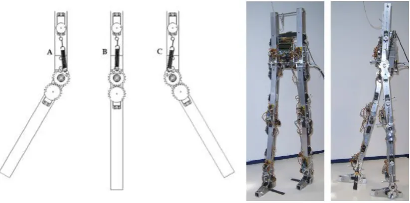
12 Figure 2-3: SEA for a biomimetic walking robot (Robinson, D., et al., 1999).
Special attention should be paid to the choice of spring constant of the elastic element. A high spring constant is required for large force bandwidth, while minimising the nonlinear friction and impedance requires a low spring constant. Therefore, during the physical actuator design process, a spring constant must be selected that represents the compromise between these two constraints. Another drawback is the size and the weight of the actuator.
2.2.4
Compact Soft Actuator
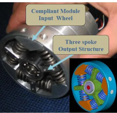
13 Figure 2-4: Compact Soft Actuator (Tsagarakis, N., et al., 2009).
In the construction of this actuator, six linear springs were placed as shown. The main function of them is to constrain the motion of the three spoke structures. These spoke structures are rotated about the motor shaft and act as a base on which to mount the output link. Two groups of position sensors are located in the actuator construction. Some of these sensors are used to measure the mechanical angle of the motor at all times; others are used to measure the deflection angle of the compliant module. Another function of these groups of sensors was to allow for evaluation of the joint torque. Whilst the benefit of the actuator is its compactness, this actuator suffers from backlash, friction, limited performance at low output impedance and high positional errors.
2.2.5
Compact Rotary Series Elastic Actuator
Kong produced a compact Rotary Serial Elastic Actuator (cRSEA) (Kong, K., Bae, J., & Tomizuka, M., 2012). This actuator is used in human assistive robots. The cRSEA
14 Figure 2-5: Compact series elastic actuator, which consists of: (a) proposed cRSEA
module; (b) thigh brace; (c) calf brace; (d) motor driver; (e) dc motor; and (f) embedded controller(Kong, K., Bae, J., & Tomizuka, M., 2012).
A significant advantage of this actuator was the ability to isolate the load from the motor using the spring. This would mean that if there is some unexpected reaction on the load side, it will not affect the driving motor. However, the large size and the complicated nature of the structure are the main drawbacks of this actuator.
2.3
Variable Stiffness Actuators
To overcome the performance drawbacks and limitations of the SEAs, researchers, especially those interested in biped robots, developed new kinds of actuators that have the ability to change their stiffness or compliance during operation. The shape of walking robots is typically human inspired, however, their actuators are often constructed of stiff and rigid parts such as motors and pulleys. Robots actuated by stiff joints can be position controlled easily. However, these robots are not safe enough to directly interact with humans and additionally are not suitable for use in an unspecified environment.
15 different environments with high flexibility. Inspired by humans, researchers have proposed a variety of types of actuators. The Variable Stiffness Actuator (VSA) is one of the most promising actuator designs for use with walking robots. The VSA operates by controlling both the actuator compliance and its equilibrium position independently. Hence, many human-like motions can be achieved using only a small amount of energy at the input of the actuator.
In the following sub-sections the most promising VSAs will be described, along with their main design concepts and any enhancements that help overcome the drawbacks and limitations of the previously described SEAs.
2.3.1
Selective Compliant Actuator
The selective compliant actuator was constructed by Sugar (Sugar, T., 2002). Figure (2-6) shows the spring system for the actuator.
Figure 2-6: The spring system for the selective compliant actuator (Sugar, T., 2002).
The selective compliant actuator is constructed using a DC servomotor and a ball screw that is used to create linear motion, and then connected in series with the linear spring. The output force of the actuator will be applied through the spring.
16 the spring. However, this actuator is constructed from heavy and large components and this was found to reduce the compliance of the system.
2.3.2
Safe and Fast Physical Human-Robot Interaction Actuator
Tonietti proposed a VSA that can be used in a robot or any other machine that may physically interact with humans (Tonietti, G., Schiavi, R. & Bicchi, A., 2005). Figure (2-7) shows the conceptual design and the actual shape of the proposed actuator.
Figure 2-7: Variable Stiffness Actuator (Tonietti, G., Schiavi, R. & Bicchi, A., 2005).
The actuator’s principle of operation is as follows: the pulleys of two DC motors 2-3 are connected to the actuator output shaft 4 through transfer belt 1. The whole system is tensioned by three spring mechanisms 5-6-7. To control the position, both motors rotate in the same direction. When a force is applied to the output in an anticlockwise direction, the transfer belt is forced against the upper spring mechanism, compressing it and introducing joint compliance. The actuator is constructed from heavy and large size components which increases the inertia of the system. Additionally the output torque generated by the actuator is limited.
2.3.3
Variable Stiffness Actuator for Safe and Performing Robots
Interacting with Humans
17 capacity of the generated torque. This means that it is not suitable for use in real robots. However, the improved VSA has been proposed to overcome these shortcomings. Figure (2-8) shows the improved VSA structure. A one-link robot arm using the improved VSA is also shown.
Figure 2-8: Improved VSA prototype and an experimental setup of the improved VSA in one-link robot arm (Schiavi, R., et al., 2008).
The experimental results showed a higher torque generation capability compared to the previous one. However, this actuator is unable to adjust position or reduce its stiffness quickly.
2.3.4
Mechanical
Adjustable
Compliance
and
Controllable
Equilibrium Position Actuator
18 Figure 2-9: MACCEPAs in three positions (A:-30o, B: 0o, C: +30o) and the walking
robot (Van Ham, R., et al., 2007).
The compliance and equilibrium position of this actuator are controlled separately using two independent motors. The relatively complex construction and difficulty controlling the performance of this actuator are considered as a drawbacks. Also the use of two servo motors reduces the efficiency of the system.
2.3.5
Mechanical
Adjustable
Compliance
and
Controllable
Equilibrium Position Actuator 2.0
[image:32.595.97.509.80.284.2]An improved version of the MACCEPA adjustable compliance actuator was suggested by Vanderborght (Vanderborght, B., et al., 2009). The modifications were achieved by selecting a suitable structure for the profile disk. In the construction of this actuator, a profile disk was used instead of the lever arm in the previous version. This flexibility in the selection of the torque-angle curve leads to considerable stiffening in the spring, which is desirable for hopping robots, or in human-robot interaction. Figure (2-10) shows the shape of the MACCEPA 2.0 actuator.
19 MACCEPA 2.0 is an electrical actuator, which uses two dedicated servomotors to control both compliance and joint position independently. As the profile disk rotates, it creates a torque at the joint but due to the larger pre-tensioning force, the joint will be stiffer. The drawback of the actuator is that it cannot support heavy loads.
2.3.6
Variable Stiffness Based on Adaptable Pivot Point
Jafari proposed a variable stiffness actuator based on the adaptive pivot point (Jafari, A., Tsagarakis, N., & Caldwell, D., 2011). Two separate motors were used to control the equilibrium position and stiffness of the proposed actuator independently. The proposed Actuator with Stiffness Adjustable (AwSA-II) is an improved version of the old AwSA; see (Jafari, A., et al, 2010). While the old version changes the stiffness by changing the spring location and arm length, the AwSA-II adjusts the stiffness using a force amplifier that depends on the lever mechanism, which is a pivot point to change the amplification ratio of the output force starting from zero to infinity. Figure (2-11) shows a graphic of the construction of the AwSA-II.
Figure 2-11: Graphical construction of the AwSA-II (Jafari, A., Tsagarakis, N., & Caldwell, D., 2011).
The stiffness of the AwSA-II does not perform against the force of the spring. The displacement of the AwSA-II is applied vertically to the spring force, and this allows
20 the stiffness to be changed efficiently. The range of the stiffness does not depend on the spring constant or lever length, and hence a light spring and short lever can be used, allowing the overall size of the AwSA-II to be minimised. On the other hand, minimising the lever arm will lead to a reduction in the time needed to regulate the stiffness of the actuator from soft to rigid.
Although this actuator is compact in size, use of rigid materials in the construction of this actuator make it relatively heavy.
2.3.7
Variable Stiffness Joint by Granular Jamming
Jiang proposed a high DOF variable stiffness joint, and demonstrated its use in a
miniature snake-like robot (Jiang, A., et al., 2012). The variable stiffness was achieved
in the proposed joint by use of granular jamming. They used a vacuum to pull the
granular-filled membrane columns; hence, the joint stiffness was raised due to jamming
of the granules. Figure (2-12) shows the structure of the variable stiffness elements.
Figure 2-12: Structure of the variable stiffness element (Jiang, A., et al., 2012).
The amount of stiffness depends on the dimensions of the membrane columns, the
granular element shape and the outer texture cover. As an example, thicker membranes
produce a lower amount of stiffness. Nonlinearity and energy loss due to friction are
21
2.4
Pneumatic Muscle Actuator
To gain compliance and safety in robots that interact directly with humans, a new type of actuator was developed. The pneumatic actuators can be used instead of SEAs and VSAs to construct a new generation of robots. Pneumatic Muscle Actuators (PMAs) can provide a high power-to-weight ratio (Byrvan, H.,et al., 2009). In addition, PMAs can be used directly without gearboxes in robot construction. Hence, they are low cost and are lightweight compared to other actuators. PMAs are physically soft and can be used to construct soft robots, that is, which do not have rigid parts in their structures. Hence, this kind of robot can interact with humans with safety.
The most promising design for the PMA is the McKibben Muscle (Schulte, H., 1962). The McKibben muscle actuator has been widely used in the construction of a new generation of robots, the so-called soft, or continuum, robots. In the following sub-sections, PMA working principles, how they are made, how they can be used, how they may be modelled, and what control strategies are used to control their behaviour will be discussed.
2.4.1
Pneumatic Muscle Actuators Structure
A PMA can be defined as a very light and soft actuator compared to traditional stiff/rigid actuators. Furthermore, PMAs can deform their shapes during operation, thus providing high flexibility. Figure (2-13) shows the geometry of the pneumatic muscle actuator.
Figure 2-13: Geometry of a McKibben Pneumatic Muscle Actuator (Chou, C., & Hannaford, B., 1996).
Nylon Shell Rubber Tube
22 McKibben’s Muscles are made as follows: the rubber tubing in the figure (2-13) forms the inner layer of the pneumatic muscle and is used to contain the air pressure. The plug, fitting and adapter are used to close the two ends of the rubber tubing. One of the ends is also used to let air in and out of the pneumatic muscle. A woven nylon shell is used as the outer layer to the pneumatic muscle; it is this braided shell that determines the behaviour of the resultant muscle when pressurised. Depending on how the braided shell is installed, the resultant actuator will either contract in response to the air pressure (contractor muscle actuator) or extend (extensor muscle actuator). These actuators are lightweight, but can generate large forces. In addition, because air is compressible the actuators are compliant. However, the actuator is only able to produce force in one direction, meaning they may be used in an antagonistic pair. This has the advantage of allowing variable stiffness through raising or lowering the total pressure in both muscles. Figure (2-14) below shows a complete pneumatic muscle.
Figure 2-14: Left extensor and right contractors pneumatic muscle actuators.
The overall shape of the PMA after assembly resembles that of a thin cylinder. Due to the behaviour of the actuators being superficially similar, at least in appearance, to a biological muscle, these actuators have been used in biologically inspired robots.
2.4.2
Pneumatic Muscle Actuator Operation
23 Depending upon how the actuator is constructed, it can operate in one of two ways. In the first method, as the actuator is pressurised its diameter increases and the braid causes a reduction in the length of the actuator. These types of muscle are commonly known as contractile muscles as they contract in length when activated. The second method of construction installs the braid in a different way. In this design, as the bladder is forced against the braid by the air pressure, the braid causes the actuator to extend in length. This type of pneumatic muscle is commonly known as an extensive muscle as it elongates when activated. In both designs, the actuator is only able to produce force in one direction – a contractile actuator only produces a tensile (pull) force and an expansive actuator only produces a compressive (push) force.
2.4.3
Pneumatic Muscle Actuator Construction
PMAs can be made in different sizes to satisfy any given required purpose. While the length of the muscle may vary from 100 mm to 4000 mm, their diameters can be between 10 mm to 70 mm (Davis, S., et al., 2003). This gives the developer the flexibility to construct effective soft robots that can satisfy a range of applications, especially in humanoid robots and human assistance robots.
2.4.4
Pneumatic Muscle Actuator Applications
The PMA can be used in many manufacturing processes. However, pneumatic muscles are yet to see widespread use in industry. In recent years, robot developers have begun to use this type of actuators extensively (Davis, S., et al., 2003). By using PMAs, a new generation of soft robots that can interact safely with a human has been produced. Due to the compliant behaviour coming from air compressibility, and the light weight of the PMA, a new range of applications can be addressed through the use of soft robots. These applications require either direct interaction with humans or must otherwise operate within an unspecified work environment.
24 An alternative method for the use of PMAs is to construct soft robots made from multiple sections of actuators connected together in series and in parallel to form continuum arms.
2.4.5
Mathematical Models for Pneumatic Muscle Actuators
There are a lot of static and dynamic models, as produced by many researchers that are used to model pneumatic muscles. Each model has a different level of complexity and its associated limitations.
Chou report simplified statics as well as a quasi-static models for both the volume and pressure dynamics of pneumatic muscles, with the hysteresis represented numerically through a static friction hypothesis (Chou, C., & Hannaford, B., 1996). Tondu present a method of representing the hysteresis in the pneumatic muscle model by introducing the effect of frictional force in the suggested model (Tondu, B., & Lopez, P., 2000). Davis presented an idea to model the hysteresis statically and by considering the braid friction (Davis, S., & Caldwell, D., 2006). The above three modelling methods depend on many parameters, that are not easy to quantify, and may change under dynamic conditions and add more complexity in controlling the operation of the PMAs.
Minh suggested another solution for the pneumatic muscle hysteresis through the use of a non-local memory to store the hysteresis function represented by a lumped parameter model (Minh, T., et al., 2009). However, only static hysteresis was considered for both extension and contraction action of the pneumatic muscle. Another limitation of the above method was that all the models presented are for the contractor muscle actuator; hence, there are no models developed for the extensor actuators yet.
2.4.6
Methods of Controlling Pneumatic Muscle Actuators
25 Depending on the type of valve, the signal used to drive the valve will vary, but it is common to drive the valve using a Pulse Width Modulated (PWM) signal, which will allow the airflow through the valve to be controlled. By changing the duty cycle and the length of the applied signal, the air pressure in the pneumatic muscle is controlled. The operational cycles of the system can be explained as follows: when the valve is on, the air supplied to the pneumatic muscle and the pressure are both increased. Hence, depending on the type of the muscle, the pneumatic muscle either contracts or extends. Alternatively, if the valve switches off, the pneumatic muscle will be relaxed. Again, by controlling the duty cycle of the PWM signal applied to the valve, the contraction or extension behaviour of the pneumatic muscle can thus be controlled.
It is necessary to state that the overall behaviour of the system is nonlinear. Hence, it is not easy to control the operation of such a system. Many researchers have proposed schemes to control the operation of the pneumatic muscles. For instance, Hesselroth report a controller based on a training algorithm of neural networks (Hesselroth, T., et al., 1994). An adaptive position controller has been produced by Medrano-Cerda (Medrano-Cerda, G., Bowler, C., & Caldwell, D., 1995), whilst a variable structure controller has been proposed by Repperger (Repperger, D., Johnson, K., & Phillips, C., 1998). Another idea for controlling the pneumatic muscle was suggested by Repperger, where a gain scheduling model-based controller was used (Repperger, D.,Phillips, C., & Krier, M., 1999). Fuzzy controllers have also been proposed to control pneumatic
26 (Choi, T., & Lee, J., 2010). Finally, a multi-parametric optimal controller was produced by Andrikopoulos (Andrikopoulos, G., et al., 2014).
2.5
Continuum Arms
Most traditional robots are built using discrete joints with stiff connecting links, as inspired by human limbs. Every joint in these robots has one degree of freedom whose movement can be straightforwardly controlled by manipulating the movement of these joints. The use of these stiff joints will result in a heavy overall structure because of the need to use large supporting sections in the overall system construction. While these stiff/rigid robots are a desirable part of many manufacturing operations, there are many applications that require robots with different features and modes of performance. In contrast to traditional robots, continuum robot arms do not have discrete joints. Instead, their entire structure can be bent to achieve a required movement. Continuum robot arms can be considered to behave in a very similar way to an elephant’s trunk, an octopus’s legs, or a caterpillar. In addition, there are no rigid links or moving joints in the construction of these types of robots (Robinson, G., & Davies, J., 1999). The movement strategies used for continuum robots depend on continuous bending along their lengths through deformation.
27 Figure 2-15: Continuum arm/appendage examples found in nature: (A) bodies of snakes; (B) giraffe tongue; (C) lizard tails; (D) tail of the spider monkey; (E) elephant trunks; (F) chameleon tails; (G) squid tentacles; (H) octopus’ arms; (K) opossum tails; and (M) chameleon tongues (Godage, I., et al, 2012).
Depending on the method and location of the actuation mechanism, a number of continuum arm designs have been developed. They may be classified into three major categories: intrinsic, extrinsic and hybrid (Robinson, G., & Davies, J., 1999).
Furthermore, these three groups can be subdivided into planar or spatial systems depending on the kind of movement they produce. While planar systems can move in one plane only by bending, spatial systems have the ability to bend in all directions along their longitudinal axis. More details on all of these systems are given below.
2.5.1
Intrinsic Planar Continuum Arm
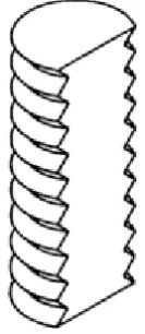
28 Figure 2-16: Intrinsic Planar Continuum Actuator (Nemir, D., 1989).
The resultant motion depends on the physical structure of the actuator walls. The axial stiffness of the actuator walls is not equally distributed around the actuator itself, and hence the elasticity of the actuator on one side differs from that of the others. Bending occurs by increasing the pressure inside this actuator. If the applied pressure is removed or decreased, the actuator motion will be changed due to the elasticity effect in straightening the actuator.
2.5.2
Intrinsic Spatial Continuum Arm
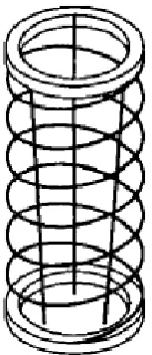
Robinson proposed the intrinsic spatial continuum actuator (Robinson, G., & Davies, J., 1998). Figure (2-17) below shows the basic structure of an intrinsic spatial continuum actuator as pressurised by fluid.
[image:42.595.217.387.553.706.2]29 This actuator can produce motion in three dimensions. Its main characteristics lie in its simple, compact and lightweight design. Both bending direction and magnitude of movement may be straightforwardly controlled by adjusting the pressure inside each of the three parallel bellows actuators. Continuum arms with many degrees of freedom can be produced by combining several actuator sections in series.
2.5.3
Extrinsic Continuum Arm
Extrinsic continuum arms are lightweight and can provide a higher number of DOF. The actuators in this type of continuum arm are located remotely, with the motion typically transferred to the main actuator by sets of tendon cables. Various structures have been introduced with different numbers of continuum arm sections and which consist of various tendon arrangements and degrees of freedom; see, for example, (Hemami, A., 1984), (Lock, J., et al., 2010), (Mahvash, M., & Dupont, P., 2010), (Su, H., et al., 2012) and (Webster III, R., & Jones, B., 2010). Figure (2-18) shows the
[image:43.595.269.338.424.585.2]extrinsic actuator.
Figure 2-18: Extrinsic Actuator (Nemir, D., 1989).
30
2.5.4
Hybrid Continuum Arm
The structure of this type of actuator has the same general appearance as the extrinsic actuator. However, it uses bellows instead of a passive spring. Figure (2-19) shows the construction of the hybrid actuator.
Figure 2-19: Hybrid Actuator (Nemir, D., 1989).
Actuation depends on the joint operation for both the bellows and the triads of three tendons arranged around the bellows. It is clear that, one tendon triad has to be connected to the middle of the bellows construction to control the shape of the lower half of the actuator. Similarly, another tendon triad must be connected to the far end of the actuator to control the operation of the upper half of the actuator. The internal pressure of the bellows controls the tension of the tendons, which works against the tendon operation. Hence, by changing the amount of the pressure in the bellows and by using different lengths of tendons the operation of the whole actuator can be controlled. Immega developed a commercial version of the hybrid actuator called a KSI hybrid actuator (Immega, G., & Antonelli, K., 1995).
2.6
Pneumatic Continuum Arms
31 I., et al., 2012). Using pneumatic actuation, fully compliant robots can be constructed because of the compressibility of air. Another benefit is the ability to use the whole arm to grasp objects because of the ability of such arms to easily bend in any direction. Hence, continuum arm robots have the ability to work in an unstructured work environment. In the following sub-sections, the most promising design for continuum soft robots will be illustrated.
2.6.1
Extensor Continuum Soft Robot Arm
McMahan developed the OctArm continuum soft robot arm, which uses PMAs (McMahan, W., et al., 2006). They use three or six extensor pneumatic muscles connected in parallel to construct each section. These extensor PMAs have the ability to provide both two-axis bending and extension in length. The OctArm IV is a four-section continuum soft robot arm with a total of twelve DOF, as shown in figure (2-20). In each section, mesh and plastic coupler were used to prevent extensor buckling.
Figure 2-20: OctArm IV extensor continuum soft robot arm (McMahan, W., et al., 2006).
OctArm IV can produce up to a 66% extension and 360o rotation in less than 0.5 seconds. The extensor continuum soft robot arm has the ability to use the entire arm for grasping and manipulating objects of a variety of sizes and scales.
The angle of the braid covering the muscle determines if the muscle is an extensor or contractor; if the angle is greater than 54o44', the actuator can be defined as an extensor,
whilst if it less than 54o44' the actuator can be defined as a contractor.
32 in each section are required to achieve bending and extension in three directions to give three DOF.
This gives the actuators located in the first two sections a greater stiffness and load capacity. In contrast, actuators in the other sections have the ability to provide higher curvature.
Extensor pneumatic muscles are susceptible to buckling, and so the OctArms includes two mesh sleeve layers. The first layer ensures the muscles remain in contact with each other during bending and prevents individual muscles from buckling. The second mesh layer, or fabric skin, is used to protect the whole arm against abrasion and wear. The OctArm sections are connected mechanically together using 16 mm thick endplates. These endplates provide the holes used to fit the actuators, and the central hole is used as a pass-through for the pneumatic tube.
Evaluation tests for the proposed continuum soft robot arms showed their ability to work in air and under water successfully, and to grasp objects by wrapping the body of the continuum manipulator around them.
The main drawback in terms of grasping for this arm was due to a lack of object-shape sensing, especially during remote teleoperation. Sometimes objects were dropped because of the lack of grip strength/grasp stability and difficulties on the part of the teleoperator in visually determining the shape of the robot.
2.6.2
Contractor Continuum Soft Robot Arm
33 arm represents its maximum length, and it contracts through operation. Figure (2-21) shows the OctArm continuum soft robot arm was constructed by using a contractor PMA.
Figure 2-21: OctArm continuum soft robot arm (Bartow, A., Kapadia, A., & Walker, I., 2013).
The PMA arrangement in the structure of the contractor continuum soft robot arm was the same as in the extensor continuum soft robot arm. Hence, the muscle diameters were the same. The nylon mesh angle set was less than the threshold angle discussed in the previous sub-section. This gives the contracting property for the proposed continuum soft robot arm.
Compared to the extensor OctArm continuum soft robot arm, the curvature capability of the contractor continuum soft robot arm is smaller. However, the extension properties matched those of the extensor OctArm.
34
2.6.3
Air-Octor Continuum Soft Robot Arm
The Air-Octor is another continuum soft robot arm constructed from multiple pneumatic sections, as proposed by McMahan (McMahan, W., Jones, B., & Walker, I., 2005). Figure (2-22) shows a two-section Air-Octor continuum soft robot arm.
Figure 2-22: Two-section Air-Octor continuum soft robot arm (McMahan, W., Jones, B., & Walker, I., 2005).
[image:48.595.241.361.185.518.2]35 Air-Octor and the previous two continuum soft robot arms. The operation of the actuator may be achieved by a combination of tendon motion and internal pressure regulation. The implementation of the Air-Octor continuum soft robot arm consists of a central air chamber that is pressurised pneumatically. The chamber is in the form of hose ducting which is sealed at both ends by end caps. The chamber is constructed from a soft air-tight fabric that is supported using a metal spring around it to form a bellows structure. Hence, the central chamber can extend and retract easily in a controlled manner as air is added to or removed from the bellows. However, the softness of the central chamber also makes it relatively fragile. Therefore, another bellows type hose was added to form an outer protection shell, allowing the arm to perform whole arm grasping without damaging the internal airtight chamber. The outer layer can also be used as a surface to which cables and sensors can be attached.
DC motors and an air pressure regulator were used to control the operation of the Air-Octor continuum arm. The DC motors were used to spool the three cables, which were used to control bending. These were mounted 120o apart around the outer layer of the
arm.
One of the main benefits gained from the design of the Air-Octor continuum soft robot arm is in the use of only one actuator per tendon. As the Air-Octor’s compliance is controlled pneumatically (higher pressure in the central chamber leads to higher stiffness).
The experimental result shows the ability to use the whole arm for grasping, picking up objects or dealing with obstacles. The payload capability of the Air-Octor arm is comparatively small when bending the trunk to pick up an object due to the pneumatic pressure used. On the other hand, the low weight of the Air-Octor allows it to bend and respond quickly to input as compared to the large payload designs, which gives it good behavioural operation for a soft, continuum manipulator.
36
2.6.4
Single Latex Rubber Tube Continuum Soft Robot Arm
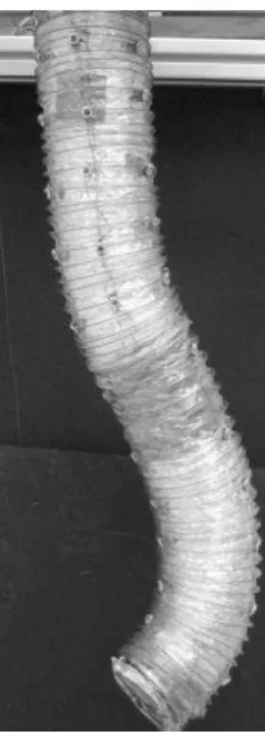
[image:50.595.154.451.258.493.2]Neppalli studded the previous Air-Octor and Oct-Arm continuum soft robot arms (Neppalli, S., & Jones, B., 2007). They then proposed a new design for the continuum soft robot arm, which uses a central main member constructed by a single latex rubber tube. The new design’s structure was similar to that of the Air-Octor continuum arm, but is considerably more robust. Figure (2-23) shows the single latex rubber tube continuum arm.
Figure 2-23: Single latex rubber tube continuum soft robot arm (Neppalli, S., & Jones, B., 2007).
37 design of the continuum trunk property is lost because of the need to use a complicated and expansive two-level control strategy. Finally, use of electrical motors reduces the compliance of the arm.
2.6.5
Granular Jamming Continuum Soft Robot Arm
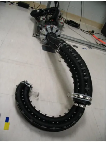
[image:51.595.156.486.353.608.2]Cheng proposed a new structure for a continuum soft robot arm based on the use of the granular jamming technique to construct the arm (Cheng, N., et al., 2012). Tension cables and spooling motors are used to control the bending of the continuum arm. Use of granular jamming allows for stiffness tuning capability. To increase the stiffness in the proposed continuum arm, a vacuum is applied to the sealed manipulator sections. Figure (2-24) shows the structure of the two granular jamming soft robot manipulators developed during this work.
Figure 2-24: Jammable manipulator. (a) First prototype of the jammable manipulator. (b) The second prototype of jammable manipulator: (left) in the unjammed state, and
(right) jammed in a corkscrew configuration (Cheng, N., et al., 2012).
Two manipulators have been developed during this work. Both have been constructed of five sections, as shown in figure (2-24). All sections in the first prototype are