© 2017, IRJET | Impact Factor value: 5.181 | ISO 9001:2008 Certified Journal | Page 2975
Model Based Embedded Control System Design for Smart Home
Neelam J. Agrawal
1,Prof Varsha S. Bendre
2, Mr. Sankara P K
31
PG student, Pimpri Chinchwad College of Engineering Akurdi Pune
2
Professor, Dept. of E & TC, Pimpri Chinchwad College of Engineering, Akurdi Pune, Maharashtra, India
3
Senior Engineer, Danlaw Inc,MG Road, Bangalore
---***---Abstract -
The notion of a smart home with integratedsensors, actuators, wireless network and a graphical user interface is very enticing. The proposed system presents the design and implementation of reliable, flexible, secure and economical sensor network for transforming traditional home into a smart home. The heterogeneous sensor and actuator nodes based on wireless networking technologies are deployed in the home environment. Hardware proposed, is going to control all home appliances in home along with exchange of data for energy and performance analysis. All devices are connected through wireless protocols, to provide seamless data transfer between control module and appliances. Complete home environment and control system is modeled in Matlab Simulink before implementation. Model based control approach is the key to develop this application, and control model will be embedded in the microcontroller board to realize the actual application. With system model and control model, will be able to perform model in loop, software in loop, hardware in loop testing. On successful testing, the actual implementation will be demonstrated with wireless network, actual loads and central processing control unit which control the home environment, using Model Based Control Design.
Key Words:Model Based Control Design (MBCD), Model
in Loop Testing (MIL), Hardware in Loop Testing (HIL), Heat Ventilation Air Conditioner (HVAC).
1 INTRODUCTION
Increasing demand for high quality product and reduce time to market are the challenges faced during the development and testing phase of any product. In traditional approach, actual product or working prototype of each subsystem is tested followed with their associated software. However, this approach increases time to market and added additional cost in case any product damage occurred during testing phase. Therefore, Model based control design is used to provide an optimum solution to overcome these challenges. In model based design approach the plant model corresponds to actual product is built in Matlab Simulink and its associated control algorithm is built in state flow. By integrating both together we can perform model in loop testing and check whether the model design is working according to the planned algorithm or not. By doing model in loop testing, one gets the competency with the actual product testing. Next successive step to model in loop testing is hardware in loop testing in which both plant model and the control algorithm are flashed into embedded controller
board. The testing report generates the actual product behaviour when it is control using control algorithm.
In the proposed system, before actual hardware implementation the product being tested using model based design approach and later being implemented on the hardware. The hardware compromises utilization of low cost wireless technologies, sensors, actuators, loads etc to introduce digitization in traditional homes and effectively build a Smart Home System. A Smart Home is usually a freshly constructed home/building that is furnished with special structured wired or wireless system that enables inhabitants to operate home appliances remotely. Smart home incorporates home automation technologies to provide occupants with information and intelligent feedback by monitoring various aspects of home [2]. By employing the network infrastructure and utilizing standard communication protocols, the household appliances can be monitored and controlled remotely over internet. A home that is equipped with such a wireless system can be called Smart Home. The Smart Home concept fundamentally brings several new features to a regular home like interoperability, remote access and flexibility of expansion [2].
2. Model Based Control Design
This section gives the overview of the steps that need to be followed while doing modeling using MATLAB Simulink. The corresponding steps included are:
Plant model development Control model development All loop testing
2.1 Plant Model Development
The plant model can be built either by using behavioural equation for any phenomenon or by assuming constant value for any quantity. Based on the physical phenomenon the equations are modelled using MATLAB Simulink library and are interconnected using wires. Various kinds of analysis and simulations can be performed using the identified model before design of a model-based controller is done.
2.2 Control Model Development
© 2017, IRJET | Impact Factor value: 5.181 | ISO 9001:2008 Certified Journal | Page 2976 end state which is being selected by the user. The entire
control algorithm is built in MATLAB environment while it is being converted into embedded C code and flashed on the microcontroller board.
2.3 Loop Testing
In case of model in loop testing, both the plant model and control algorithm are in the MATLAB environment. The interconnection is provided between plant model and its associated control algorithm to validate whether the plant model is giving response in accordance with the control state flow.
Fig.1 Model based design workflow
Since here both the plant and controller are in the model formed the named given as model in loop testing. In other words it is named as software in loop testing.
Fig.2 Hardware in loop testing
However, in case of hardware in loop testing; the plant model is converted into embedded code and then gets
flashed on to the real time personal computer whereas control algorithm is also converted into corresponding code and then burned on embedded controller board. Both real time personal computer and embedded controller board gets integrated to do validation of product.
3. Products Design and Development
This paper presents the model based design and development of the three products including water heater, air conditioner and ceiling fan.
3.1 Water Heater Model
The phenomenon which is taken into consideration while modelling heater model is the law of thermodynamics and the heat transfer phenomenon including conduction, convection and radiation. The main role of the water heater model is to transfer the heat available on the heater cross-sectional area to the water surrounding heater surface. The concept comprises that the when the supply voltage is applied the temperature of heater go on increasing because of which the convection phenomenon takes place in the water surrounding the heater surface. The molecules of water get energized by absorbing heat from the heater surface and starts vibrating [5].
This energized particle during their motion transforms their energy to the low energized particle making them to vibrate, thus making the entire water in the container to become hot. While modeling it is considered that the energy can neither be created nor destroyed simply it converts from one form to another. Therefore, the entire heat energy available with the heater is transformed to the water during the time when the heater is ON.
The equation of the heat transform by means of convection is:
Q =h * A * temp difference Where
Q represents the rate at which the heat is transformed between the surfaces.
h represents the heat transform coefficient. A represents the surface area of the heater.
3.2 Air Conditioner Model
© 2017, IRJET | Impact Factor value: 5.181 | ISO 9001:2008 Certified Journal | Page 2977 The same principle is used while modeling the
temperature variations phenomenon of the air conditioner. In model both the outside and inside room temperature variations are taken into account. The equation relates the Newton’s Law cooling is given below:
Where
K represents cooling coefficient. TH represents hot body temperature. TC represents cold body temperature.
dT/dt represents the rate of change of room temperature with respective to time.
In addition to the temperature variations, humidity control provision is also provided in the model. Humidity is taken into account because in order to avoid suffocation in the room, it is expected that the humidity ratio should be in accordance with the current room temperature. According to the definition of relative humidity, it seems that it is inversely proportional to the temperature.
Relative humidity is defined as the ratio of actual amount of water vapour present in the air to the maximum capacity of air to hold water vapour at that temperature. It tells how much closer the air is to being saturated. The equation is given below:
*100%
In the model to maintain equivalent ratio of humidity in the room atomizer is used, which is the source of water vapour. Thus, by varying the atomizer value we can control humidity in the room.
3.3 Ceiling Fan Model
While modeling ceiling fan model, the air change rate concept is used. The air change rate is defined as the number of times the air enters or leaves the room per hour, because of which exchange of heat from our body to ambient happens. Hence, we feel cold when the fan is turn ON.
The steps that are used while doing model design is explained below:
1. First step is to identify the required air changes needed for the use of the room. In model, we consider this air change rate as a constant value [8]. 2. Then calculate the volume of the room which is
given by (length*breadth*height).
3. After that multiply the volume of the room by the required air change happens in the room.
4. In step four divide the answer by 60 minutes per hour to find the required air circulation happens in the cubic feet meter.
Where
V represents volume of the room in cubic feet meter.
Air change rate is assumed as constant value say 5.
4. Experimental Results
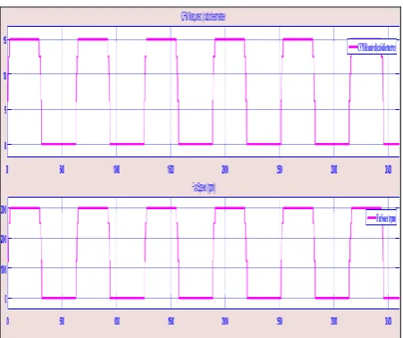
The experimental waveforms show that how all the three products are controlled by taking control input into user hand.
1) For water heater model the variations of water temperature in regard with heater ON/OFF status is observed. It is shown in figure 3.
Figure 3:Water Temperature variations w.r.t heater status
[image:3.595.313.565.240.742.2]2) For air conditioner model the temperature and humidity variations in the room is observed in regard with the compressor and atomizer ON/OFF time. It is shown in the figure 4 to figure 5.
© 2017, IRJET | Impact Factor value: 5.181 | ISO 9001:2008 Certified Journal | Page 2978 Figure 5: Relative humidity variations w.r.t Atomizer
Status
3) For ceiling fan the air circulation in the room is observed by varying the rotational speed of the fan. It is shown in the figure 6.
Figure 6: Air Circulation variations w.r.t Fan Speed
5. Conclusion
The study states that the model based design approach is seems to be useful in validating the product performance and it reduces the challenges faced during the development and testing phase of any product life cycle i.e it helps in enhancing time to market and provides high quality product. To integrate traditional home into smart home all three home appliances including water heater, air conditioner and ceiling fan are modeled in MATLAB Simulink and gets controlled using control state flow algorithm. The experimental waveforms states that all the three products are operated automatically by taking control input in user hand.
Acknowledgement
I would like to thank Whirlpool of India Ltd, Pune for giving me such a great opportunity and also for their continuous technical support. Also I would like to thank PCCOE Pune for allowing me to do internship for my PG project. I will sincerely thank to Mr Sankarapandian, Ex lead Engineer of Whirlpool for their valuable guidance. At the last but not least, I am thankful to my parents, who encouraged and inspired me with their blessings.
Future Work
In future the code generation of both plant model and control algorithm will be done and gets flashed into the embedded microcontroller board to control devices from remote end and also the energy consumption of each devices for the time they gets ON will be displayed.
References
[1] Ashutosh Bhatt [et.al], “Cost effective digitization of Home Appliances for Home Automation with low-power Wi-Fi devices” International Conference,IEEE 2016.
[2] Yuan lin [et.al], “Study of Smart Home system based on Cloud Computing and the key Technologies, International Conference on Computational Intelligence and Communication Networks, 2015.
[3] Simon Alt[ et.al], “Model-based Temperature and Humidity Control of Paint Booth HVAC Systems ”,IEEE 2015.
[4] Socci Vince [et.all], “Implementing a Model-based Design and Test Workflow”, International Symposium Systems Engineering, IEEE, 2015.
[5] Haresh A. Suthar, Dr. Jagrut J. Gadit, “Modelling and Analysis of the Simple Water Heater System,”IJECE Vol.1, No.1, September 2011.
[6] Water Heater University – Electric water heaters: How they work
Available:
http://waterheateruniversity.com/electric-waterheater.html
[7] Basic Modelling Workflow - MATLAB & Simulink Available:
http://in.mathworks.com/help/simulink/gs/basicmode lingrkflow.html
[8] Air change calculation – HVAC System Availbe:
[image:4.595.49.275.370.559.2]© 2017, IRJET | Impact Factor value: 5.181 | ISO 9001:2008 Certified Journal | Page 2979