© 2017, IRJET | Impact Factor value: 5.181 | ISO 9001:2008 Certified Journal | Page 2805
PSEUDO RANDOM TRC BASED TEST PATTERN GENERATOR IN LOW
POWER APPLICATION
SeemaSerin.A.S
1, Ramya.R
2, Poongodi.M
3, Marutharaj.T
41
PG Scholar, Department of ECE, Theni kammavar Sangam College of Technology, Tamilnadu, India.
2PG Scholar, Department of ECE, Theni kammavar Sangam College of Technology, Tamilnadu, India.
3PG Scholar, Department of ECE, Theni kammavar Sangam College of Technology, Tamilnadu, India
4Assistant Professor, Department of ECE, Theni Kammavar Sangam College of Technology, Tamilnadu, India.
---***---Abstract -
Design for testability (DFT) consists of ICdesign techniques that add testability features to a hardware product design. Tests are applied at several steps in the hardware manufacturing flow and for the certain products, may also be used for hardware maintenance in the customer’s environment. DFT plays an important role in the development of test programs and as an interface for test application and diagnostics. A built-in self-test (BIST) is a mechanism that permits a machine to test itself. The main purpose is to reduce the complexity, and thereby decreases the cost and reduces reliance upon external test equipment. Ideally, a BIST scheme should be easy to implement and must provide high fault coverage. The linear feedback shift register (LFSR) is commonly used as a TPG in low overhead BIST. LFSR reduces the correlation between the consecutive pseudorandom test patterns which in turn may result in more switching activities and power dissipation during test mode. A new low transition test pattern generator (TPG) using twisted ring counter technique was introduced to overcome the power dissipation but didn’t do the much of repair. So to overcome these two different techniques are proposed. Pseudo random twisted ring counter technique and MUX-ed twisted ring counter TPG technique. Also to avoid glitches filtering twisted ring counters are used. These techniques are developed by using Verilog HDL language and simulations are carried out using Altera quartus II tool.
Key Words: Twisted ring counter (TRC), Test pattern generator (TPG), Built-in self-test (BIST), Linear feedback shift register (LFSR), Automatic test pattern generator (ATPG), Low transition test pattern generator (LT-TPG).
1. INTRODUCTION
The increased complexity of IC’s manufacture and reduced access to internal node has been made it not only more difficult to diagnosis but also to locate faulty components. To avoid this, fault diagnosing testable design is the key to develop complex hardware/software systems. Design for testability is the design technique that makes the testing easier. It consists of IC design techniques that add testability features to a hardware product design. Tests are applied at several steps in the hardware manufacturing flow and for the certain products, may also be used for hardware maintenance in the customer’s environment. The tests are generally driven by test programs that execute using automatic test equipment. The response of vectors from a good circuit is compared with the response of vectors from a device under test. The objective of design for testability is to improve the controllability and observability of internal circuit nodes so that the circuit can be tested effectively. Automatic test pattern generation is much easier if appropriate DFT rules and suggestion have been implemented. Automatic test pattern generator is the design automation method/technology used to find an input or test sequence that, when applied to digital circuit, enables automatic test equipment to distinguish between the correct circuit behaviors caused by defects. Built-in self-test is one of the main techniques which are used under the test pattern generator. The main function of the test pattern generator is to apply test patterns to the unit under test. This increases the controllability and the observability of the chip thereby making the test generation and fault detection easier.
© 2017, IRJET | Impact Factor value: 5.181 | ISO 9001:2008 Certified Journal | Page 2806 dissipation during test mode. This can cause heat effect,
and seriously influence the life span of a circuit under test when exceeding the threshold of temperature. Therefore, reducing energy dissipation during test application is becoming an important objective in circuit design. Due to the excessive switching activity, power consumption will increase, thus reducing battery lifetime, and also causing heat dissipation which may permanently damage the circuit under test. To overcome this switching activity and generate the more number of test pattern vectors twisted ring counter are used.
Twisted ring counter test pattern generator, will configure the linear feedback shift registers to work as multi-segment twisted ring counters. During the test mode the first twisted ring counter will be triggered directly by the system clock, while the second segment of the twisted ring counter will be connected to a control signal produced from the previous stage of the counter, and so on for the next segments. The multi segmented twisted ring counter produce more number of test pattern vectors as well as reduces the power dissipation of the circuit. However it reduced the power dissipation it produced some glitches of the circuit which cause some delay of the test pattern vectors. To avoid this cause the newly proposed techniques are introduced i.e. pseudo random twisted ring counter TPG and the Mux-ed twisted ring counter TPG.
1.1 Built-in self-test
A built-in self-test is a mechanism that permits a machine to test itself. The main purpose is to reduce the complexity, and thereby decreases the cost and reduces reliance upon external test equipment. A widely accepted approach to deal with the testing problem at the chip level is to incorporate BIST capability inside a chip. This increases the controllability and the observability of the chip, thereby making the test generation and fault detection easier. The main function of the test pattern generator is to apply test patterns to the unit under test. The resulting output patterns are transferred to the output response analyzer. Ideally, a BIST scheme should be easy to implement and must provide high fault coverage.
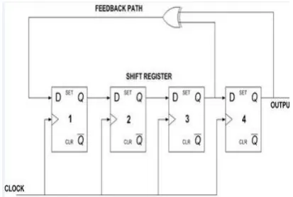
1.2 Linear Feedback Shift Register
Linear feedback shift register is a shift register whose input is a linear function of its previous state. The only linear function of single bit is XOR, thus it is a shift register whose input bit is driven by the XOR of some bits of the register is deterministic, and the stream of values produced by the register is completely determined by its current state. The seed is used to generate a test pattern and their corresponding test cube. An LFSR generates
periodic sequence must start in a non-zero state, the maximum length of an LFSR sequence is 2n-1 does not generate all 0s pattern.
The linear feedback shift register is commonly used as a TPG in low overhead BIST. This is due to the fact that an LFSR can be used not only as a TPG, but also as a test response analyzer with high fault coverage and low hardware overhead. However, the random character of test patterns generated by LFSR reduces the correlation between the consecutive pseudorandom test patterns and in each test pattern as well, which in turn may result in more switching activities and power dissipation during test mode. This can cause heat effect, and seriously influence the life span of a CUT when exceeding the threshold of temperature. Therefore, reducing energy dissipation during test application is becoming an important objective in circuit design. While the test mode operation has not normally been a predominant concern.
[image:2.595.343.550.448.587.2]The power consumed during test mode operation because of the high switching activity in the nodes of the circuit under test during test. The main reason why the switching activity is high during test is the low correlation between the consecutive vectors generated by the LFSR which applied to the primary inputs of the CUT. As a result of the excessive switching activity, power consumption will increase, thus reducing battery lifetime, and also causing heat dissipation which may permanently damage the CUT.
Fig -1: Linear feedback shift register
© 2017, IRJET | Impact Factor value: 5.181 | ISO 9001:2008 Certified Journal | Page 2807 In these test methods, which is widely adopted in the
design of combinational circuits (test-per-clock) and the sequential circuits (test per-scan), most of the CUT nodes undergo switching while applying test patterns. Hence, a substantial amount of the power dissipation occurs during this operation because of the uncorrelated patterns produced by the LFSR.
Several techniques that have been developed to reduce the power dissipated during test can be found. A direct technique to reduce power consumption is by running the test at a slower frequency than normal mode. This technique of reducing power consumption, while easy to implement, significantly increases the test application time.
Another category of techniques used to reduce the power consumption in scan based BIST is by using scan-chain ordering techniques. These techniques mainly aim to reduce the average power consumption during scanning in test vectors and scanning out captured responses by arranging the scan cells which cause more internal circuit transitions to the positions with low transitions weights in the scan chain. One of the drawbacks of these ordering algorithms is that they deal with a deterministic set of test vectors, while in fact random test vectors which are generated by random or pseudorandom TPGs such as the LFSR are widely used in BIST.
1.3 Twisted Ring Counter
Twisted ring counter also called as Johnson counter is another basic of application of shift registers with a feedback. Twisted ring counter is the same as the normal ring counter (also called circular shift registers), except that the inverted output of the first flip-flop is used to feed the last flip-flop.
To overcome the excessive switching activity of the linear feedback shift register and producing more number of consecutive test pattern vectors multi segmented twisted ring counter are used. It reduces the power dissipation of the circuit under test. In the multi segmented twisted ring counter 6-bit twisted ring counter are divided into two main property i.e. 6-bit divided by 2 twisted ring counter which produce 36 test pattern vectors and the second 6-bit divided by 3 twisted ring counter which produce 64 test pattern vectors.
[image:3.595.317.520.108.175.2]In 6-bit divided by 3 twisted ring counter, six numbers of D flip-flop (A0, A1, A2, A3, A4, A5) are using each one is using as a 2-bit. In the first set of twisted ring counter the inverter output of the A0 is connected to the A1 and the clock signal for A2, A3 are generated by anding the logics of A0, A1 and the global clock.
Fig -2: 6-bit divided by 3 twisted ring counters
The second set of the twisted ring counter the inverter output of the A2 is connected to the A3 and the clock signals for A4, A5 are generated by anding the logics of A2, A3and the global clock. Finally the third set of the twisted ring counter the inverter output of the A4 is connected to the flip-flop A5. Which produce the output sequences of 4*4*4=64 test pattern vectors.
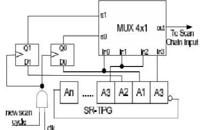
Multi outputs of the twisted ring counter test pattern generator in a full scan based built-in self-test , an output of a cell of the test pattern generator will be used to scan-in the test vectors scan-in to the scan-inputs and memory elements. Using multi-segment twisted ring counter TPG can obtain huge power savings in scan-based BIST.
Fig -3: Multi-outputs of the TRC-TPG
In multi-outputs of the twisted ring counter test pattern generator, the selection lines of multiplexer are connected to the output of D flip-flops, the inputs of D flip flops are connected to the twisted ring counter test pattern generator. The clock functions for both the flip-flops are generated by gating the global clock with the new scan cycle. When the inputs are 1 then the flip-flop will transparent the data as the selection lines for multiplexer. If S0 and S1 both are low the test pattern generator from A1 will be generated as output. If anyone input is high then the test pattern generator from A3 will be generated as output.
[image:3.595.341.548.406.540.2]© 2017, IRJET | Impact Factor value: 5.181 | ISO 9001:2008 Certified Journal | Page 2808 some delay to produce the test pattern vectors.
Multi-outputs of the twisted ring counter test pattern generator gives more power dissipation which may cause the circuit under test.
2. LITERATURE SURVEY
Tyszer J. et al, describes a new pseudorandom test pattern generator with pre selected toggling activity. It is comprised of a linear finite state machine driving an appropriate phase shifter and armed with a number of features that allows this device to produce binary sequences with low switching rates. Liang F. et al,
describes a test pattern generator for BIST. This method generates multiple single-input change vectors in a pattern, each vector applied to a scan chain is an SIC vector. A reconfigurable twisted ring counters and a scalable SIC counter are developed to generate a class of minimum transition sequences. Bin Zhou et al, describes a low power test-per-clock built-in self test scheme based on 2-bit TRC. The low power during testing can be obtained by selectively activating multi 2-bit twisting ring counters. The low power test-per-clock BIST scheme has the improved performance including power, fault coverage and test length. The advantage of the low power test-per-clock BIST scheme can be used for testing more than one module in a system on a chip. Abu-Issa A.S. et al, describes a low-transition linear LFSR that is based on the output sequence of a conventional LFSR. This design is called bit-swapping LFSR. When used to generate test patterns for scan-based built-in self-tests, it reduces the number of transitions that occur at the scan-chain input during scan shift operation by 50% when compared to those patterns produced by a conventional LFSR. Hence, it reduces the overall switching activity in the circuit under test during test applications. Wang S. et al, describes a low hardware overhead TPG for scan-based BIST that can reduce switching activity in circuits under test. The BIST TPG decreases transitions that occur at scan inputs during scan shift operations and hence reduces switching activity in the CUT.
3. PSEUDO RANDOM TWISTED RING COUNTER
[image:4.595.315.527.101.213.2]From the previous design we were using the flip flops to the circuit which gives more power dissipation and cause the circuit under test. To overcome this problem we have replaced the flip-flops and using the tristate buffers in the circuit. In pseudo random mux-ed test pattern generator, the selection lines of multiplexer S0 and S1 are connected to the outputs of the tristate buffer1 and the tristate buffer2. The inputs of the tristate buffers are connected to the twisted ring counter test pattern generator. The clock functions for both the tristate buffers are generated by gating the global clock with the new scan cycle.
Fig -4: Pseudo random mux-ed twisted ring counter If the new scan cycle and the clock logic and gate are goes high then the tristate buffer1 control line becomes active which transmit the data of A1to the selection line S1. If the new scan cycle and the clock logic and gate are goes high then the tristate buffer2 control line becomes active which transmit the data of A2 to the selection line S0. While comparing to the previous design the current logic takes the advantages of reducing the circuit area and power reductions and the leakages of the circuit.
3. SIMULATION RESULTS
[image:4.595.309.511.426.530.2]The simulation results of the pseudo random mux-ed twisted ring counter TPG are given below
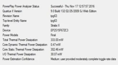
Fig -5: Pseudo random mux-ed TRC test pattern generator
Fig -6: Power analysis of pseudo random muxe-ed TRC test pattern generator
4. CONCLUSIONS
[image:4.595.310.503.558.665.2]© 2017, IRJET | Impact Factor value: 5.181 | ISO 9001:2008 Certified Journal | Page 2809 generator we using the flip-flops in the multi-outputs of
the test pattern generator though it generates the fastest random test pattern generator the power dissipation was high. To overcome this problem we have replaces the flip-flops using the tristate buffers in the pseudo random mux-ed twistmux-ed ring counter test pattern generator, which gives fastest random test pattern generator, as well as reducing the power dissipation and reducing the circuit area
REFERENCES
[1] Rajski,J.;Tyszer,J.;Mrugalski,G.;Nadeau-Dostie,B.,"Test
generator with pre selected toggling for low power built-in self- test," in VLSITest Symposium(VTS), 2012 IEEE 30th, vol., no., pp.1-6,23-25April2012.
[2] Bin Zhou; Xinchun Wu, "A Low Power Test-per-Clock
BIST Scheme through Selectively Activating Multi Two-Bit TRCs," in Instrumentation and Measurement, Computer, Communication and Control (IMCCC), 2014 Fourth International Conference on , vol., no., pp. 505-509, 18-20 Sept. 2014.
[3] A.S. Abu-Issa and S.F. Quigley, “Bit swapping LFSR
and scan-chain ordering: a novel technique for peak and average power reduction in scan based BIST”, IEEE Transactions on Computer-Aided design of Integrated Circuits and Systems,28(5), May 2009, pp. 755-759.
[4] Abu-Issa, A.S.; Quigley, S.F., "A multi-output
technique for high fault coverage in test-per-scan BIST," in Design and Technology of Integrated Systems in Nano scale Era, 2008. DTIS 2008. 3rd
International Conferenceon, vol., no., pp.1-6, 25-27 March2008.
[5] S. Wang, “A BIST TPG for Low Power Dissipation and
High Fault Coverage”, IEEE Transactions on Very Large Scale Integration (VLSI) Systems, Volume 15, Issue 7, July 2007, pp. 777-789.
[6] A.S. Abu-Issa and S.F. Qiugley, “Bit-swapping LFSR for
low power BIST”, Electronics Letters, 44(6), March 2008, pp. 401-403.
[7] Mahendra Nourani, Mohammad Tehranipoor,
NisarAhamed, “Low-Transition Test Pattern Generator for BIST-Based Applications”, IEEE TRANSACTIONS ON COMPUTERS, VOL. 57, NO. 3, MARCH2008.
[8] ChethanJ, Manjunath Lakkannavar, “Design of Low
Power Test Pattern Generator using Low Transition LFSR for high Fault Coverage Analysis”, I.J. Information Engineering and Electronic Business, 2013, 2, 15-21.
[9] M. Tehranipoor, M. Nourani, and N. Ahmed, “Low
Transition LFSR for BIST-Based Applications”, Proc. Of the 14th Asian Test Symp. (ATS 05), IEEE, Dec 2005, pp. 138 -143.
[10] S. Wang and S. Gupta, “LT-RTPG: a new test-per-scan