© 2017, IRJET | Impact Factor value: 6.171 | ISO 9001:2008 Certified Journal
| Page 353
IMPACT OF WINDOW CONFIGURATION IN ACHIEVING VISUALLY
COMFORTABLE ENVIRONMENT IN AN ARCHITECTURAL DESIGN
STUDIO- A CASE OF SPAV DESIGN STUDIO
Ar.Asis Nath
1, Ar.P. Sitha Mahalakshmi
21
Student, M.Arch[Sustainable Architecture],School of Planning and Architecture,
Vijayawada, Andhra Pradesh, India
2
Assistant Professor, Department of Architecture,
School of Planning and Architecture, Vijayawada, Andhra Pradesh, India.
---***---Abstract -
Vijayawada, “The Business capital of AndhraPradesh” is one of the denser cities in India, with warm and humid climate according to ECBC. With clear sky conditions for maximum period of the year, the city experiences about 80000 lux of average illumination. This naturally available resource of daylight can be effectively utilised in internal spaces for providing ample illuminance with suitable strategies. One such exercise has been done studying an architectural design studio of size 6.4m x 13.1m with an area 83.83m2 in SPA University, in Vijayawada. This studio
experiences direct and diffused light through one external wall facing north. This wall consists of four windows of size 1.8m x 1.6m with a sill level of 0.9m (2.9m2) accounting for less than
one sixth of the floor area .The existing scenario of the studio in terms of its components i.e. walls, roof, floor, windows and doors , and their characteristics like sizes, materials, its reflectivity were studied . The component window is studied further in terms of its configuration. This paper aims at achieving visual comfortable working environment in that design studio. This is done through analysis of existing conditions of the studio with varied window configurations namely (1) Horizontal windows (2) Vertical windows (3) Composite windows. Validation of the results was done through simulations using computer generated window configurations in Radiance IES-Ve software with clear-sky conditions. The results thus obtained suggest that, vertical window configurations proved to be the best for achieving desirable visual working environment for the studied design studio.
Key Words: Design studio, optimisation, IES-Ve, window sizes, day lighting.
1. INTRODUCTION
Light, plays an important role in the quality of human life. The day light from the sun gives energy that can be used to reduce artificial lighting requirements inside a building. Also, adequate ventilation and air exchange is prime concern for maintaining comfortable humidity and temperature for Vijayawada. Day lighting is the most important criteria to be looked upon to in terms of either availing or cutting down, while designing an educational building. It brings positive
energy and sense into a work place that impacts health, level of stress and performance of students [1].
Studios, quite defines the relation between a teacher and student but also defines the relation between student [2]. In addition to that studio gives a sense of informal layout that invokes better cooperation among the students. Quite a number of scholars have reported the use of studio configuration as an outstanding model of education [3]. In School of Planning and Architecture, Vijayawada, the studio is used more than for just classroom activities. From minute detail drawing to model making projects the studio demands good amount of day lighting. It has been proven that good amount of day lighting reduces dependence on artificial lighting. In modern studios task lighting are incorporated to help maintain the required lux levels along with the day lighting available during day time.The height and size of window are the major variables needed to get the preferred value of natural light (Gregge and Ander in 1995) [4]. This study helps in understanding the existing lighting levels in one of the architectural studios of SPA, Vijayawada and helps in working towards optimal window configurations to achieve desired daylight factor as per National Building Code of India (2005).
2. AIMS AND OBJECTIVES
Being the student at SPA University I have been willing on understanding day lighting level inside the design studio. With increase in studio depth there is decrement in lux level. So, the study focuses on achieving optimum illumination level for comfortable working condition in an architectural studio in SPA, Vijayawada. Emphasis has been given on increasing daylight inclusion to the North facing room. The objective of the study is as follows:
1. To explore the quality of luminous intensity inside
the north facing architectural studio.
2. To identify parameters that can help to improve the
luminous environment of the considered studio.
3. To recommend better window configuration to
© 2017, IRJET | Impact Factor value: 6.171 | ISO 9001:2008 Certified Journal
| Page 354
3. STUDIO SPACE CHARACTERSTICS OF SPA
VIJAYWADA
Architectural studio has a history of large open design with natural lighting where each student is allocated a desk for drafting and construction of models manually [5]. This helps in providing visually comfortable working conditions during day for drafting, model making and studying.
Though with rapid development in technology and introduction to soft-wares like Autodesk AutoCAD, Revit
Architecture etc. to assist architecture students replacing
manual drafting with computer aided design, most of
architectural schools still believe in manual
drawing/drafting techniques as to create a strong base in fundamentals.
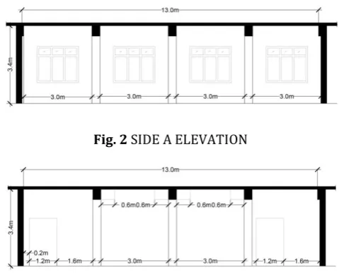
Case Description: The building is oriented east-west axis to optimize a position as since the sun path can have a significant influence on the level of illuminance on North side of the block. As is in the Fig.1 (Plan of studio), the studio
considered in SPA Vijayawada is located in 1st floor of the
building complex, on the right wing in which windows are facing North side. The studio measures 6.4m x 13.1m
(83.83m2) having clear ceiling height of 3.4m. It holds a
capacity of 18 students. To the South and West of studio is a corridor of 3m and an indoor gathering space of 9.1m respectively. The requirement of lighting is the most important consideration for this type of classroom, therefore the recommended components for these types of building must be used to improve the condition of day lighting [6]. Students face east while the light comes from the students left side (North) from four windows of size 1.8m x 1.6m. The drafting table is suitable for the paper size of 0.92m x 1.3m
and therefore each space occupied 3.5m2 to 4.5m2 per
student. PJ Waldram in 1913 explained that the ratio of the glazing area to floor area is one tenth in order to obtain the minimum requirement of day lighting [7]. The present window to floor area percentage is 13.2 %.
[image:2.595.313.553.89.285.2]Fig. 1 PLAN OF STUDIO
Fig. 2 SIDE A ELEVATION
Fig. 3 SIDE B ELEVATION
4. BACKGROUND STUDY
4.1 CLIMATE OF INDIA AND VIJAYAWADA
India lies between 20.5937° N and 78.9629° E. The
climate of India on the widely-used classification by Atkinson (Koenigsberger, 1973) is characterized as Tropical Monsoon climate. Vijayawada located at 16.5193°N, 80.6305°E and has an altitude of 11.0m. Vijayawada has a warm-humid climate with hot summers and a monsoon season (Energy Conservation Building Code classification). Temperatures can reach 320K in May–June, while the winter temperatures rarely fall below 288K. The average humidity is 78%, and the average annual rainfall is 0.9m. Vijayawada gets its rainfall from both the southwest monsoon and northeast monsoon [8].
4.2 STUDIES FROM BUILDING CODE
National building code of India states that for a warm and humid climate, the minimum Window to Floor area ratio should not be less than one-sixth of the floor area. According to “Indian standard, Code of Practice for Day lighting of educational buildings”, recommended illumination levels on work areas for educational buildings is:
1. Lux Level – 150 to 300 lux
2. Daylight factor – 1.9 to 3.8
3. Reflection factor for Ceiling – 0.8 to 0.7
4. Reflection factor for Walls – 0.7 to 0.5
5. Reflection factor for floors – 0.35 to 0.25
© 2017, IRJET | Impact Factor value: 6.171 | ISO 9001:2008 Certified Journal
| Page 355
TABLE – 15. METHODOLOGY
The existing indoor day lighting conditions of North facing studio is compared with day lighting condition of 3 variable opening condition of same studio to achieve the required Daylight factor as per National Building Code of India. Three research models of same architectural studio having different window sizes with window area as per NBC are developed through software. The existing studio plan had room size of 6.4m x 13.1m with window sizes of 1.8m x 1.6m with sill level of 0.9m from floor level. The external wall 2.8m away from considered window is kept constant throughout the simulation. The considered studio
configurations are located on the 1st floor and the ceiling
height is kept constant 3.4m through the model. The day light factor having maximum area on working is recorded. Area excluding 0.9m from all side of wall surface is assumed to be the working plane. The resultant daylight factor values of all three models are compared with existing value of the studio.
A. Configurations
Three configurations are modeled in terms of three different window configurations. All the windows area is maintained
to one sixth of floor area (13.3m2) according to NBC but with
varying width and length.
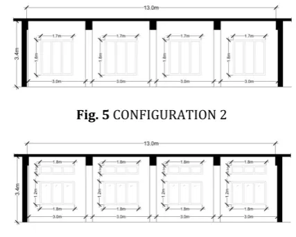
Configuration-1: The model has a horizontal window language finished with window size – 2.5m x 1.2m with a sill level of 0.9m from floor level (Figure 4). The Window area is
13.5m2.
Configuration-2: The model has a vertical window language finished with window sizes – 1.7m x 1.8m with a sill level of
0.6m from floor level (Figure 5). The Window area is 13.4m2.
Configuration-3: The model has a composite window language finished with window sizes – 1.8m x 1.2m with a sill level of 0.9m from floor level and sky light of 1.8m x 0.5m
(Figure 3). The Window area is 13.3m2.
[image:3.595.324.538.90.261.2]Fig. 4 CONFIGURATION 1
Fig. 5 CONFIGURATION 2
Fig. 6 CONFIGURATION 3
6. SIMULATION
The current study uses IES<VE> (Integrated Environmental Solution) program to evaluate the average daylight factor in the considered architectural studio in India. Table-2 shows the parameters for simulation in Vijayawada. The CIE standard clear sky was assumed for sky condition according to the climate of India. The value of reflectance for wall, floor, and ceiling are 50% (grey), 25% (darker shade of grey), 100% (white) respectively is considered as per existing room color. According to CIE standard the transmittance of the glazing is 80% in the simulation of the models. The ceiling and wall have equal reflectance than from floor. The calculations for estimating the Daylight factor were taken on
three period of the year June 21st (summer solstice), March
21st (equinox), December 21st (winter solstice). For
simulation 12 pm is considered for observation to avoid any effect of shadows from adjacent structures on day light values recorded inside the studio.
7. RESULTS AND DISCUSSIONS
Reading from 21 March (Equinox)
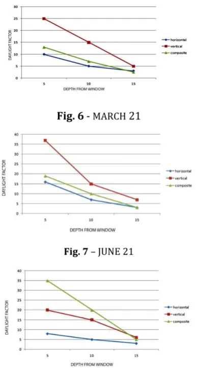
The simulation was executed to know the better configuration among three to achieve desired Daylight factor on Equinox (equal day equal nights). It is found out that Vertical configuration is most desirable having highest daylight factor value 5 (on lower side of values) at 4.6m depth while horizontal window is desirable but with less Daylight factor values. It is seen that composite configuration allows light but less penetration than vertical configuration (Table 3).
Reading from 21 June (Summer Solstice)
The simulation was executed to know the better configuration among three to achieve desired Daylight factor on Summer solstice (longest day). At this period of time the sun remains at highest altitude and provides maximum illumination. It is found out that Vertical configuration is Period of
year 22 June 21Mar& 23 Sept 22 Dec
altitude 83 74 51
time 12p
© 2017, IRJET | Impact Factor value: 6.171 | ISO 9001:2008 Certified Journal
| Page 356
most desirable having highest daylight factor value 7 at 4.6mdepth (on lower side of values) while horizontal window and composite window are desirable but with less Daylight factor values. It is seen that vertical configuration allows maximum light of Daylight factor value 37 (on higher side of values) along with most penetration (Table 4).
Reading from 21 December (Winter Solstice)
The simulation was executed to know the better configuration among three to achieve desired Daylight factor on Winter solstice (Shortest day). During this period the sun has low altitude drifting towards Southern side. It is found out that Vertical configuration is most desirable having highest daylight factor value 6 at 4.6m depth (on lower side of values) while horizontal window and composite window are desirable but with less Daylight factor values. It is
[image:4.595.304.572.173.273.2]observed that composite configuration allows maximum light of Daylight factor value 35 (on higher side of values) but with little less penetration than Vertical configuration (Table 5).
TABLE-2 Information for IES computer simulation
Dates of simulation June 21st , March 21st, December 21st Time of simulation 12 pm
Locations latitude
and longitude Vijayawada, 16.5193°N, 80.6305°E Andhra Pradesh,
Sky condition CIE standard clear sky
Reflection of wall 50% Reflection of floor 25%
Reflection of
[image:4.595.28.567.330.445.2]ceiling 50% Transmittance glazing of 80%
TABLE 3 – SIMULATION ON 21ST MARCH (READING UP TO 4.6m DEPTH FROM WINDOW)
FUNCTION Window
To Floor area Req. (m2)
Window To Floor area (m2)
Daylight Factor Required In studio Daylight Factor Recorded Desired/ Not desired
Existing 13.3 7.8 3 14.5 to 2.5 Not desirable
Configuration 1
(Horizontal) 13.3 13.5 3 10 to 3.0 Desirable
Configuration 2
(Vertical) 13.3 13.4 3 25 to 5.0 Mostly Desirable
Configuration 3
(combination) 13.3 13.4 3 13 to 2.5 Not Desirable
TABLE 4 – SIMULATION ON 21ST JUNE (READING UP TO 4.6m DEPTH FROM WINDOW)
FUNCTION Window
To Floor area Req. (m2)
Window To Floor area (m2)
Daylight Factor Required In studio
Daylight
Factor Recorded Desired/ Not desired
Existing 13.3 7.8 3 14 to 2.5 Not desirable
Configuration 1
(Horizontal) 13.3 13.5 3 16 to 3.0 Desirable
Configuration 2
(Vertical) 13.3 13.4 3 37 to 7.0 Mostly Desirable
Configuration 3
(combination) 13.3 13.4 3 19 to 3.0 Desirable
TABLE 5 – SIMULATION ON 21ST DECEMBER (READING UP TO 4.6m DEPTH FROM WINDOW)
FUNCTION Window
To Floor area Req. (m2)
Window To Floor area (m2)
Daylight Factor Required In studio
Daylight
Factor Recorded Desired/ Not desired
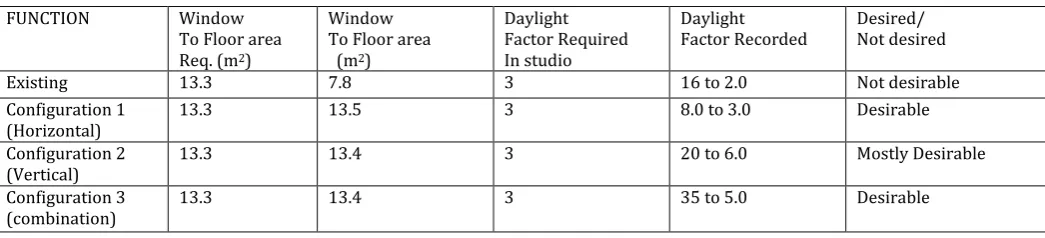
Existing 13.3 7.8 3 16 to 2.0 Not desirable
Configuration 1
(Horizontal) 13.3 13.5 3 8.0 to 3.0 Desirable
Configuration 2
(Vertical) 13.3 13.4 3 20 to 6.0 Mostly Desirable
Configuration 3
(combination) 13.3 13.4 3 35 to 5.0 Desirable
[image:4.595.28.566.480.597.2] [image:4.595.33.556.631.750.2]© 2017, IRJET | Impact Factor value: 6.171 | ISO 9001:2008 Certified Journal
| Page 357
AnalysisFrom the figures (6,7,8) it is observed , the performance of vertical window configuration is best among the three providing better penetration and achieving the desired Daylight factor in all three configuration models. For large depth room, vertical windows provide better illumination. Though composite configuration have good results for winter solstice daylighting, decay factor increases during summer and equinox providing less light at interior. The horizontal windows fails to distribute light in portion of working plane. It can be said that small rooms can be equiped with horizontal windows where working plane is nearer to window.It is observed that the Window to Floor area ratio as per National Building Code fullfills the criteria to achieve desried level of illumination. Varying ceiling height, position of skylights and obstruction distance opposite to opening have varied effect on the sizing of the window.
Fig. 6 - MARCH 21
Fig. 7 – JUNE 21
Fig. 8 – DECEMBER 21
8. SCOPE AND LIMITATION
The analysis aims at daylight level at Noth facing
Architectural studio at 1st floor. Study can be done on basis
[image:5.595.308.559.241.312.2]of different orientation, time and alternative floor levels for further findings.As Vijayawada is hot area, radition acompany the light through windows. Therefore adavanced study can be done in optimizing the window size and thermal gain solutions.
TABLE – 6
BEST GOOD NORMAL
TYPE VERTICAL COMPOSITE HORIZONTAL
DF 7 5 3
DF
DESIRED 3 3 3
Vertical configuration is found most efficient for the architectural studio due to its high level of penetration and low decrement factor. Composite windows can be made equally efficient by optimising the lintel height and ceiling height. The thumb rule of window area one sixth of floor area (WFR) as in National Building Code of India, is analysed and found correct for achieving the required day light level. It can be concluded that North facing studio can have efficient constant illumination with proper window configurations.
ACKNOWLEDGEMENT
I would like to express my deepest gratitude to all those who provided me the possibility to complete this paper. A special acknowledgement I give to our faculty, Asst.Prof.P. Sitha MahaLakshmi, whose contribution in stimulating suggestions and encouragement, helped me. I would like to mention that her continuous support, guidance, comments and advices has helped me improve.
REFERENCES
[1]. J. R. Benya, Lighting for Schools, National Clearing House for Educational Facilities, Washington DC, December 2001.
[2]. N. Abdullah, et al., “Architecture Design Studio Culture and Learning Spaces: a Holistic Approach to the Design and Planning of Learning Facilities, Procedia-Social and Behavioral Sciences, vol. 15, pp. 27-32, 2011.
[image:5.595.64.258.337.700.2]© 2017, IRJET | Impact Factor value: 6.171 | ISO 9001:2008 Certified Journal
| Page 358
[4].G. D. Ander, Day lighting performance and design, NewYork: Vann Nostrand Reinhold, 1995, p.p.8-10-16.
[5].D. J. Neuman and S. A. Kliment, “Building type basics for college and university facilities, vol. 3, Hoboken, NJ: John Wiley, 2003, p.p.120.
[6].N.Baker and F. a. Steemers, Day lighting in architecture, a European Reference book, London, James & James, 1993, p.p. 1.9- 2.9-2.12.
[7] .W.Wu and E. Ng, “A Review of the Development of Day lighting in Schools, Lighting Research and Technology, vol. 35, 2003.p.p. 111124.
[8].Climatic Data of Vijayawada, Prof. Dr. Ramesh Srikonda (Director In charge, Dean of Studies, Head of Arch. Department.
[9].National building code of India 2005, Bureau of Indian standards, ISBN 81-7061-026-5.
[10].Indian standard Code of Practice For Daylighting Of Educational Buildings, 2004, UDC 628-921/928:727.
ANNEXURE FOR FIGURES
All the annexure are the derived results from the simulations
EXISTING CONFIGURATION - DAY LIGHTING SIMULATION RESULTS
MARCH 21
JUNE 21
DECEMBER 21
CONFIGURATION 1: HORIZONTAL – DAY LIGHTING SIMULATION RESULTS
© 2017, IRJET | Impact Factor value: 6.171 | ISO 9001:2008 Certified Journal
| Page 359
JUNE 21DECEMBER 21
CONFIGURATION 2: VERTICAL – DAY LIGHTING SIMULATION RESULTS
MARCH 21
JUNE 21
DECEMBER 21
CONFIGURATION 3: COMPOSITE – DAY LIGHTING SIMULATION RESULTS