Real Time Drowsiness Detection System using Viola
Jones Algorithm
Rohan Putta
Fr. Agnel Institute ofTechnology Sector 9-A
Vashi, Navi Mumbai-400703 Maharshtra, India
Gayatri N Shinde
Fr. Agnel Institute ofTechnology Sector 9-A
Vashi,Navi Mumbai-400703 Maharshtra, India
Punit Lohani Fr. Agnel Institute of
Technology Sector 9-A
Vashi, Navi Mumbai-400703 Maharashtra, India
ABSTRACT
Among the many problems faced by the country, deaths and injuries due to road traffic accidents are extremely common. Driver’s drowsiness is one of the major reasons which lead to these mishaps. In this paper, we are discussing a ‘Real Time Drowsiness Detection System’ which could determine the level of drowsiness of the driver. This system considers both the closing of eyes and yawning as the constraints for determining the degree of drowsiness.
Viola Jones Algorithm is used for facial features detection. Primary attention is given to faster detection and processing of data. Driver’s drowsiness will be detected by checking whether the eyes are closed over some particular consecutive frames and similarly it can be checked if the driver is yawning by monitoring the mouth region. If the closing of eyes and yawning indicates that the driver is drowsy then an alarm will be triggered.
General Terms
Feature Detection, Computer Vision, Machine Learning
Keywords
OpenCV, Viola-Jones Algorithm, Haar Classifier
1.
INTRODUCTION
Road accident is global tragedy with over-rising trend. India suffers from the highest number of deaths –around 1,05,000 in absolute terms annually-due to road accidents in the world owing to the poor infrastructure and dangerous driving habit. The increasing number of traffic accidents due to a diminished driver’s vigilance level has become a serious problem for the society. Statistics show that 20% of all the traffic accidents and up to one-quarter of fatal and serious accidents are due to drivers with diminished vigilance level.
Most motor vehicle crashes are caused by driver error (e.g. speeding) or poor operating practices including lack of seat belt use, distractions, fatigue, rash driving, and alcohol or drug use while driving. Most of the road users are quite well aware of the general rules and safety measures while using roads but it is only the laxity on part of road users, which cause accidents and crashes. Of all these issues, the most important issue to be considered is the driver’s concentration as well as driver’s inattention or distraction. Therefore, human behaviour factors affecting the driver’s performance are important and should be considered while implementing the reliable systems to assure safe driving.
2.
LITERATURE SURVEY
Viola Jones Algorithm[1] forms the basis of this robust system. Viola jones algorithm helps in achieving high detection rates. It also processes the images rapidly. It forms the basis of most of the real time systems as it works only on the present single grey scale image. There are three main parts of this algorithm:
Integral Image[1] which allows very fast feature evaluation.
Classifier function[1] which is built using small number of important features.
The method of combining the classifiers in a cascade structure[1] to increase the speed of the detector by focusing on the promising regions of interest.
Viola Jones Algorithm is fast, efficient and gives level of accuracy.
First step of viola jones algorithm includes training of the data set using any machine learning algorithm. The training is done using the two sets of positive and negative images. Basically this training is done in order to develop predictive relationship between the data sets. In the Viola–Jones object detection framework, the Haar-like features are therefore organized in something called a classifier cascade to form a strong learner or classifier. The key advantage of a Haar-like feature over most other features is its calculation speed. Due to the use of Third is the method of combining the classifiers in a cascade structure to increase the speed of the detector by focussing on the promising regions of interest. a Haar-like feature of any size can be calculated in constant time (approximately 60 microprocessor instructions for a 2-rectangle feature).
After the classifier function is developed, AdaBoost algorithm[3] is used for selecting the required features and training the data set. This algorithm basically is used for enhancing the performance of the classifier function. AdaBoost is an effective procedure for searching out a small number of good “features” which nevertheless have significant variety. This algorithm is used for selecting the features like eyes or mouth region. After selecting the features of interest the data sets are trained.
2.1
Integral Image
The integral image at location (x, y) contains the sum of the pixels above and to the left of x and y. It is the summation of all the pixel values in an original image.[1][2].
2.2
Haar-Feature
Haar features are composed of either two or three rectangles. Face candidates are scanned and searched for Haar features of the current stage. The weight and size of each feature and the features themselves are generated by the learning algorithm- AdaBoost[3] . Each Haar feature has a value that is calculated by taking the area of each rectangle, multiplying each by their respective weights, and then summing the results. The area of each rectangle is easily found using the integral image. The coordinate of the any corner of a rectangle can be used to get the sum of all the pixels above and to the left of that location using the integral image. By using each corner of a rectangle, the area can be computed quickly[1][2].
2.3
Classifier
A Haar classifier uses the rectangle integral to calculate the value of a Haar feature. The Haar classifier multiplies the weight of each rectangle by its area and the results are added together. Several Haar classifiers compose a stage. A stage accumulator sums all the Haar classifier results in a stage and a stage comparator compares this summation with a stage threshold. The threshold is also a constant obtained from the AdaBoost algorithm. Each stage does not have a set number of Haar features. Depending on the parameters of the training data individual stages can have a varying number of Haar features[1][2].
2.4
Cascade
The cascade eliminates candidates by making stricter requirements in each stage with later stages being much more difficult for a candidate to pass. Candidates exit the cascade if they pass all stages or fail any stage. A face is detected if a candidate passes all stages[1][2].
3.
DESIGN
There are two basic steps in this project –
3.1
Classifier Training
In this project around 1000 positive images and 5000 negative images were taken as sample datasets in-order to train the Face, Eye and Mouth Classifiers. The Output of Viola Jones Algorithm are the Classifier files – face.xml, eye.xml and mouth.xml.
This step is performed only once during the execution of the project and at the beginning. The input to the Drowsy Detector Algorithm are these xml Classifier files.
[image:2.595.322.567.82.481.2]3.2
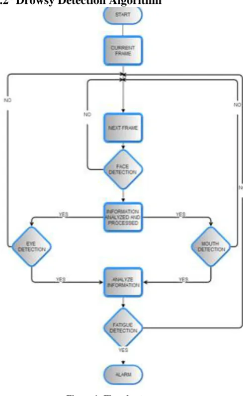
Drowsy Detection Algorithm
Figure 1: Flowchart.
Drowsiness of a person can be measured by the extended period of time for which his/her eyes are in closed state. In this system, primary attention is given to the faster detection and processing of data. The number of frames for which eyes are closed is monitored. If the number of frames exceeds a certain value, then a warning message is generated on the display showing that the driver is feeling drowsy.
In this algorithm, first the image is acquired by the webcam for processing. Then the Haarcascade file face.xml is used to search and detect the faces in each individual frame. If no face is detected then another frame is acquired. If a face is detected, then a region of interest in marked within the face. This region of interest contains the eyes and mouth. Defining a region of interest significantly reduces the computational requirements of the system. After that the eyes and mouth are detected from the region of interest by using eye.xml and mouth.xml respectively.
The following are the main modules of our Algorithm is –
3.2.1
Image Acquisition
3.2.2
Face Detection
The face area is detected using the haardetectobjects() function[4] for which the face classifier xml file is passed as a parameter to the function .The number of detected Faces is stored in a vector .Rectangular region of interest are then marked for the detected faces.
3.2.3
Eyes and Mouth Detection
The eye area and Mouth area are also detected using the haardetectobjects() function for which the eye.xml and mouth.xml classifier xml files respectively are passed as a parameter to the function .The number of detected eyes and mouth are stored in a vector. Rectangular region of interest are then marked for the detected eyes and mouth.
3.2.4
Decision Making Table
The following are the four test-cases that could be encountered while executing this project.
Table 1. Preliminary cases
3.2.5
Alarm System
When the eyes are closed for more than three frames then it is deducible that the driver is feeling drowsy and similarly if the mouth is open for more than three frames, then it is deducible that the driver is yawning. Hence these cases are detected is detected and an alarm sounded.
4.
IMPLEMENTATION
4.1
Viola Jones Algorithm using Haar
classifier in OpenCV
The output of the Viola Jones Algorithm is a trained Haar Classifier that is stored in a XML File which can be loaded using the OpenCV function: cvLoad()[4] and then cvHaarDetectObjects()[4] is used to find objects similar to the ones it was trained on to train our own classifiers to detect other objects such as faces , eyes and mouth.
This has been done with the OpenCV haartraining application[4], which creates a classifier from a training set of positive and negative samples .Steps are described below:
4.1.1
Creation of Positive Dataset Directory
Positive dataset means the collection of the object which is required to be detected by the system. In this case the positive dataset will contain the images which have faces. These may be stored in one or more directories indexed by a text file in the following format[3][5]:<path>/img_1 count_1 x11 y11 w11 h11 x12 y12 . . .
<path>/img_2 count_2 x21 y21 w21 h21 x22 y22 . . .
Each of these lines contains the path (if any) and file name of the image containing the object(s). This is followed by the count of how many objects are in that image and then a list of rectangles containing the objects. Here the starting value of the rectangles are stored followed by the width and height pixel values.
In order to get the maximum accuracy in detecting the face region, eye region and mouth region, taking into consideration more datasets will be necessary. The output of this process finally creates a directory file in the positive.txt [5].
In the case of the positive dataset for faces, the pixel value of rectangles bounding the face will be stored and similar case goes with the eyes and mouth.
4.1.2
Creation of Vector File
The utility application createsamples[4] is used to build a vector output file of the positive samples. This vector file is used as the input for the training function.
For example:
createsamples –vec face.vec –info positive.txt –w 30 –h 40
This takes the positive.txt file and outputs a formatted training file, face.vec. Then createsamples extracts the positive samples from the images before normalizing and resizing them to the specified width and height (here, 30-by-4) [5].
4.1.3
Creation of Negative Dataset Directory
The Viola-Jones cascade is a binary classifier: It simply decides whether or not the object in an image is similar to the training set. Any image that doesn’t contain the object of interest can be turned into a negative sample. It is useful to take the negative images from the same type of data. That is, if one wants to learn faces in online videos, for best results one should take their negative samples from comparable frames .However, comparable results can still be obtained using negative samples taken from any other source. Again the images are put into one or more directories and then an index file is made consisting of a list of image filenames, one per line. For example, an image index file called negative.txt. [5].4.1.4
Training of the Classifier
With the creation of all the datasets one can train the classifier. The OpenCv[4] documentation provides set of haar training commands and functions which can be used for training the classifier. The following haar training command [3][5] is used in the project:
Haartraining / –data face /
–vec face.vec –w 30 –h 40 / –bg negative.txt/
–nstages 20 / –nsplits 1 / [–nonsym] / –minhitrate 0.998 / –maxfalsealarm 0.5
The face.vec file contains the information regarding the positive dataset. The negative.txt gives the information regarding the negative dataset. The cascade goes through a total of 20 stages in the training process.
TEST CASES
EYE CLOSURE
YAWNING RESULT
CASE-1 NO NO AWAKE
MESSAGE
CASE-2 NO YES STOP
YAWNING MESSAGE
CASE-3 YES NO ALARM
In the case of the project the classifier was executed thrice in order to train the following three classifiers-face.xml, eye.xml, mouth.xml
4.1.5
Creation of .xml files
For this project face, eye and mouth classifiers are required. So the learning objects method is used to create the haarclassifier .xml files. The haarcascade files are one for the face, one for the eyes and one for the mouth. Around 1000 positive and 5000 negative samples were taken. It took a long time to train them. Finally face.xml and eye.xml, mouth.xml files are created.
These xml files are directly used for object detection using haardetectobjects()[4] function. It detects a sequence of objects (in this case our face, eyes and mouth). Haarcascade-eye.xml is designed only for open eyes. Hence no of eyes detected=2. So when eyes are closed the system doesn’t detect anything. Hence no of eyes detected=0. When this variable is ‘0’ for more than three frames, the driver is observed to be drowsy and an alarm is triggered.
4.2
Algorithm for Driver Drowsy Detection
System.
Referring to the table 1,
In each of the 4 cases, 4 frames are considered .In the initial 3 frames no message is displayed because there are no sufficient frames to make the decision. In the 4th frame a decision is made based on the previous 3 consecutive frames.
In the Project, the primary condition is ‘CLOSING OF EYE’ and secondary condition is ‘YAWNING’
.
4.2.1
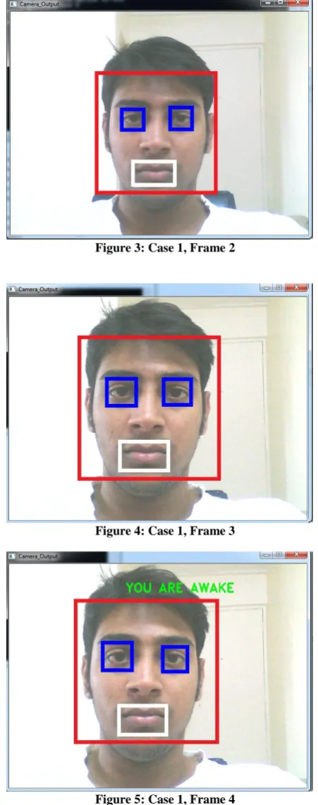
CASE-1:
[image:4.595.311.537.75.646.2]In this case the driver’s EYES are open and MOUTH is closed i.e the driver is not yawning, so the message displayed is “YOU ARE AWAKE”.
Figure 2: Case 1, Frame 1
Figure 3: Case 1, Frame 2
Figure 4: Case 1, Frame 3
Figure 5: Case 1, Frame 4
4.2.2
CASE-2
[image:4.595.53.272.497.668.2]Figure 6: Case 2, Frame 1
[image:5.595.312.533.73.255.2]Figure 7: Case 2, Frame 2
Figure 8: Case 2, Frame 3
Figure 9: Case 2, Frame 4
4.2.3
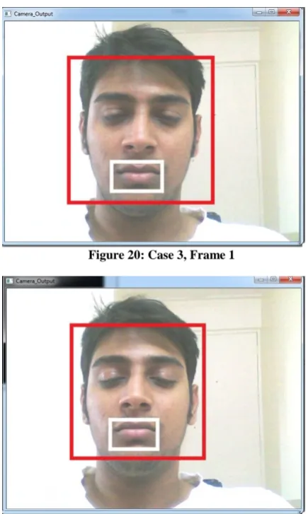
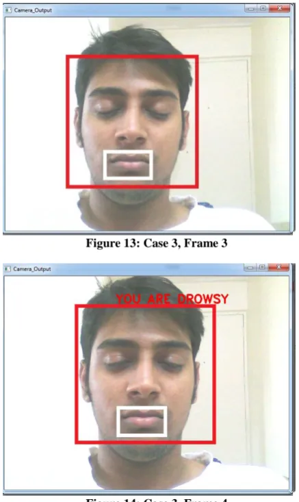
CASE-3
[image:5.595.52.276.75.642.2]In this case the driver’s EYES are closed and MOUTH is also closed, which means that the primary condition is satisfied i.e. Driver is drowsy, so the message displayed is “YOU ARE DROWSY”.
Figure 20: Case 3, Frame 1
[image:5.595.314.532.325.689.2]Figure 13: Case 3, Frame 3
Figure 14: Case 3, Frame 4
4.2.4
CASE 4
[image:6.595.52.271.73.440.2]In this case the driver’s EYES are closed and MOUTH is also open i.e the driver is yawning, it means that the driver is very drowsy, so the message displayed is “YOU ARE DROWSY”.
Figure 15: Case 4, Frame 1
Figure 16: Case 4, Frame 2
Figure 17: Case 4, Frame 3
Figure 18: Case 4, Frame 4
5.
ANALYSIS OF THE ALGORITHM
The Time Analysis Bar Chart can be seen in the Figure 19.The following is the Time Analysis of the Drowsy Detection Algorithm.
[image:6.595.54.272.509.679.2]Thus, the Drowsy Detection System finds whether the driver is sleepy or not in around 0.5-0.6 seconds.
6.
CONCLUSION
The algorithm presented in this paper forms the basis of many ‘Real Time System’ which gives highly accurate results in less time .This system was built keeping in mind every possible behavior of the driver and also the need for a quick computed result which is accurately achieved by the Viola Jones algorithm which is the backbone of Drowsy Detector Algorithm.
In the current system when the multiple faces are detected the results are inaccurate. The optimum result would be, if multiple faces are detected then only the driver’s face should get detected. This could be achieved using the Depth Calculations wherein the area of the rectangles of multiple faces are calculated and the largest area is selected since in most of the cases the driver’s face would be ahead and all the extraneous faces would be behind the driver. The rectangle which is ahead would obviously have a larger area than the rest of the detected faces and so selecting the largest area rectangle would be appropriate.
GSM Technologies such as messaging service can be included. Continuous monitoring of the Driver’s fatigue level should be done and based on that a decision should be made and a message should be sent to the Driver’s related person.
It is important to have an integrated processor while implementing this system on the vehicle which in-turn would
be connected to the GSM System. Also it would be necessary to have a display system which would show the driver’s face if the driver has to do any adjustment to the camera.
7.
ACKNOWLEDGEMENT
We express our sincere gratitude to our project guide Mrs.Vijayalakshmi Puliyadi for her help and support. Without her guidance it would not have been possible to complete our project successfully.
8.
REFERENCES
[1] P. Viola et M. Jones, Rapid object detection using boosted cascade of simple features, Proceedings IEEE Conf. on Computer Vision and Pattern Recognition 2001.
[2] Junguk Cho, Shahnam Mirzaei, Jason Oberg, Ryan Kastner “FPGA-Based Face Detection System Using Haar Classifiers” FPGA'09, February 22-24, 2009, Monterey, California, USA. ACM 978-1-60558-410-2/09/02.
[3] G. Bradski and A. Kaehler, “Learning OpenCV: Computer Vision with the OpenCV Library,” O'Reilly Media, Inc., 2008.
[4] OpenCv Documentation.