Area Efficient Counting Bloom Filter (A-CBF)
design for NIDS
Brindha.P
Assistant Professor Department of ECE
Velalar College Of Engineering And Technology, Erode, Tamilnadu.
Senthilkumar.A,
PhD. Professor& HeadDr.Mahalingam College Of Engineering And Technology,
Pollachi, Tamilnadu.
ABSTRACT
An interesting target for the intruders is computers, since valuable data are fed into it. The need for impeccable intrusion detection system is growing every day. Hardware based Network Intrusion Detection System (NIDS) relies upon power, delay and area. The Counting Bloom filter (CBF), improves the power and speed of membership test by maintaining a hazy and compact representation of large set to be searched. Our proposed architecture utilizes an array of Linear Feedback Shift Register (LFSR) along with tri-state buffers. Circuit simulation is shown for 8-bit count per entry. Simulation results show that proposed architecture is 35% hardware efficient compared to Low Power Fast Counting Bloom Filter (L-CBF) and Static Random Access Memory based Counting Bloom Filter (S-CBF).
General Terms
Network Intrusion Detection System, Static Random Access Memory
Keywords
Counting Bloom Filters, Area efficient counting bloom filter (A-CBF), Intrusion Detection System, Linear Feedback Shift Register, Tristate buffer.
1.
INTRODUCTION
A Network Intrusion Detection System (NIDS) attempts to detect malicious activities such as denial of service attack, port scans or tries to cracks into computers by monitoring network traffic. NIDS monitors all incoming packets and tries to find suspicious patterns known as signatures or malwares. These are decided by a network administrator at the time of configuration and deployment of the network intrusion detection system based on the security and network policies of the organization. Since the number of threats and network speed increases day by day, the conventional software based NID system such as Snort utilizes more processing time; hence it is difficult to cope with both protection and higher data rates. As a result, custom hardware implementation of network intrusion detection started emerging, which can have significant contribution for pernicious detection.
Extensive researches exist on general pattern matching algorithms. The Boyer–Moore algorithm is widely preferred for its efficiency [2]. But, this algorithm is inefficient for multiple patterns [3]. This problem is solved by Aho and Corasick algorithm which uses the Finite automation for concurrently matching multiple strings [4].
Fig 1: FPGA based NIDS.
The implementation of the Aho-Corasick algorithm has been done for Snort, by Mike Fisk [5] and Marc Norton [6], respectively. Fisk and Varghese presented a multiple-pattern search algorithm that combines the one-pass approach of Aho-Corasick with the skipping feature of Boyer–Moore [7]. All these approaches are developed mainly for software implementation. To examine packets in real time with full network link speed, a hardware solution is more favorable.
A Bloom filter, conceived by Burton Howard Bloom in 1970, is a space-efficient probabilistic data structure [8]. Bloom filters are created to perform membership queries. Bloom filters are scalable and compact, so they are employed in Intrusion Detection System (IDS). Bloom filters provide the output matched or not matched based on the hash bits. It implements a set membership test using a series of Monte Carlo tests with one-sided error: Each test may return positive in error [8].The probability of a false positive is at most 1/2 on any one test and therefore can be made exponentially small by repeating the test with independent random choices.
A Bloom filter (B,H) implements an approximate set membership test for a set S ⊂ U using a bit array B consisting of m bits initialized to zero and k independent hash functions H = {hj : U → [m], j ∈ [k]}; the hash functions map elements of the input space U to locations in B. The set S is represented by evaluating each of the k hash functions for each object x ∈ S and setting the corresponding bits in B to one given a key x ∈ U and a Bloom filter (B, H), can be verified and determined whether x is definitely not or might be a member of S by hashing x under the hash functions H and examining the corresponding bits in B[8]. If any bit is still zero then we know that x / ∈ S; if all k hash functions point to bits that are one then we conjecture that x ∈ S but may be wrong.
Recall that a false positive is said to occur when all k hash functions index ones in B for an element x ∈U \S. The false positive rate of the Bloom filter is the proportion of U \S for which a false positive occurs [8].
Let ρ be the proportion of bits that remain zero in B. Note that the false positive rate depends on both ρ and k while ρ is also dependent on k. Given that each of the k hash functions maps each x ∈ S to a location in B at random (i.e. the location is chosen uniformly in B and each choice is independent), the expected value of ρ is
E(ρ)=(1-1/m)nk
---(1)
This is simply the probability that a given bit in B remains 0 after the locations are sampled locations in B independently at random with replacement nk times.
Earlier bloom filters are designed to hold one bit at a cell. So each ‘1’ in the cell indicates data matched and ‘0’ indicates data not matched. In order to have multiple access to a line leads to development of CBF’s, where the single cell in Bloom filters is replaced by a counter and this counter keeps track of the data entries, deletion and matching of signatures.
CBF’s are used to improve the energy and delay characteristics [9]. L-CBF is an efficient implementation that utilizes an array of up/down LFSR and local zero detectors. Previous works use SRAM, but recent development in L-CBF includes LFSR based on CBF together with SRAM memory increases the speed of the signature detection.
The significant contribution of this work is as follows: 1. Counting Bloom Filter
2. Proposed area efficient CBF design. 3. Comparison on power, area and delay.
The rest of the paper is organized as follows. Section II describes previously designed architecture L-CBF. Section III illustrates the area efficient architecture (A-CBF). Section IV shows the sketch of the physical layout. Section V shows the implementation results.
2.
COUNTING BLOOM FILTER
This section reviews the low power counting Bloom filter and its characteristics.
2.1
Low Power Fast Counting Bloom Filter
(L-CBF)
[image:2.595.315.552.70.217.2]The Signatures are stored in static memory in the hardware. The energy consumed by the bit lines and word line is quite large. To reduce the access towards the memory, Bloom filter concept comes into picture. A single Bloom filter cell can store one pattern at a time. So, to speed-up the pattern matching process, multiple Bloom filter cells are preferred [10]. The main disadvantage relies on multiple accesses towards the same line. In order, to overcome this, an array of counters is used to store the signatures. In this way, the counter keeps track of the multiple accesses and avoids errors. And also CBF reduces the need to read/write over long bit lines. In this concern, CBF produce ‘1’ or ‘0’ which indicates the presence of pernicious signatures as depicted in Fig.3. So any counters that produce deterministic up/down sequence can be a choice for CBF. LFSR is a good choice which reduces the delay and power.
Fig 2: L-CBF counting bloom filter architecture
2.1.1
Hash Module
The Fig.2 depicts the architecture of L-CBF. The TCP/IP packets are taken as input to detect the malicious packets as shown in Fig.3.
TCP/IP Packet
Fig 3: Hash Function
The packets are first passed through the universal hash function block based on the random value ‘dij’[11].
X=< X1, X2, X3…….X6> --- (2)
hi(X)=di1.Xi1 di2.Xi2 di2. Xi2……. --- (3)
Where “.” is bit wise AND operator. is a bit wise XOR operator. dij is a predetermined random number which is in the range of (0, ….m-1) and X is input signatures. The hi(x) indicates the hash function output. By varying the random number dij,one may be able to get different hash output [9]. The single hash might lead to false positive. To deduce the false positive, multiple hash functions can be employed.
2.1.2
Decoder Module
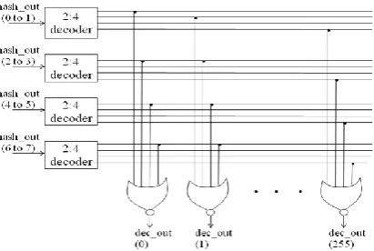
The normal decoder is replaced by the hierarchical decoder which has pre-decoder and local decoder designs [13]. The pre-decoder has four 2:4 decoder modules. The local decoder has NOR gates to provide 0:255 outputs. The decoder can be designed using NAND-NOR combination, since it consumes less power compared to any other gates.
Fig 4: Hierarchical decoder
[image:2.595.321.527.609.747.2]2.1.3
Partition Module
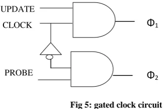
Each partition module consists of a gated clock, LFSR counter and Zero detector. The gated clock circuit is required for a power efficient architecture as shown in fig.5
UPDATE
CLOCK
[image:3.595.333.501.75.171.2]PROBE
Fig 5: gated clock circuit
The counter is preferred to track the multiple line access when the hash output is similar [9]. The up/down counter is needed to enhance the signature updating and for deletion operation.
Upon all other synchronous counters [12], LFSR is preferred due its low power consumption. When LFSR is clocked, it advances the signal through the register from one bit to the next most-significant bit (see Fig.7). Some of the outputs are feedback and combined in exclusive-OR configuration to form a feedback mechanism. A linear feedback shift register can be formed by performing exclusive-OR on the outputs of two or more of the flip-flops together and feeding those outputs back into the input of one of the flip-flops.
The Zero detector acts as a checker to test the presence of the pernicious data. L-CBF gets 8-bit entry and produces the output based on op-select signal. The basic operations are,
i. Increment ii. Decrement iii. Probe iv. Idle
Initially all the modules are reset to make the output zero.
3.
AREA EFFICIENT COUNTING
BLOOM FILTER
As the technology grows, the main criterion is miniaturization of ICs with low power consumption. In this way, so many types of hardware modules are designed to make an efficient signature matching. Early design started with the storing of signatures in SRAM and matching it with the test signatures [13][14][15]. The bit-line and word-line become difficult and consume large amount of power. To overcome this, a small hardware is designed to reduce the memory access.
The Bloom filter is used only to speed up the process and to reduce the power. The architecture shown in Fig.6 deduces the access to the bit line and save the power. Hence, whenever the output bit is zero, definitely the input signature is not a member and no pernicious data is present. Once the output bit is ‘1’, then definitely the input signature is a pernicious one. To have an exact match, the large search with original database is needed as depicted in Fig.6.
[image:3.595.65.236.128.240.2]Another significant parameter is false positive. To enhance the pernicious detection, multiple hashes are employed. By exploiting this method, more that 90% of the false positive problems are avoided.
Fig 6 :Flow sheet to show the large search
3.1
Linear Feedback Shift Register
The maximum length 3-bit LFSR is used with sequences 2n-1 states. The LFSR is a shift register and few XNOR gates fed by a feedback loop. XOR gate is preferred where permutation goes through all possible states except zero [16][17][18]. The up/down LFSR used in Bloom filter should have the permutation state “000”. This state indicates that pernicious signature is not present in the counter. So XNOR gate is used for this type of applications.
Up/down LFSR has the polynomial i. g(X)=1+X2+X3 for up count. ii. h(X)=1+X+X3 for down count.
Fig 7:3-bit LFSR counter
3.2
D-Flip flop
The Fig.7 depicts the LFSR used in L-CBF which consumes huge bit slices with reduced delay and power, when compared to basic LFSR design [17]. The huge gate count should be reduced to scale the design. Finally based on the mux output, the search has to be extended or aborted as shown in flow chart Fig.6.
The clocking scheme used in LFSR has two non-overlapping clock ф1 and ф2. The global clock is taken as ф1 and the inverted form of global clock is taken as ф2 [12].
Fig 8:D flip flop with two phase clock
Φ
1 [image:3.595.316.534.311.448.2] [image:3.595.324.535.615.709.2]3.2.1
Update Mode
The above Fig.8 shows the clocking scheme with two non-overlapping clocks. Each D flip flop in the LFSR is replaced with the above clocking scheme. The ф1 clock is enabled by the gated clock circuitry when the architecture is in update mode. So the bit is stored in the D1 flip flop. But it is not moved out of D2 since ф2 is disabled. Now the power consumption is reduced by half by using gated clock circuitry.
3.2.2
Probe mode
In the probe mode, the D2 will be in active mode and D1 will be in inactive mode in the same sense. In update mode, depending upon the operation select signal it may be in increment or decrement mode [9].
In increment mode, the data base can be updated (i.e.,) the pernicious signature can be added. The virus patterns increase in a rapid rate. Hence for, for the best architecture should be able to compete with these new patterns. Hence this increment mode provides the user with improving the database as new patterns are introduced and renowned in the future. As of the increment mode, the decrement mode is used to delete the patterns if it is found to be innocuous signatures.
3.3
Modified D flip flop
[image:4.595.317.544.71.194.2]The D flip flop with two phase clock is replaced with basic D flip flop with single clock scheme as shown in fig.9
Fig 9: LFSR with tri-state buffer
The output of the D flip flop is given to tri-state buffer. The basic operation of a tri-state buffer is, to buffer the output when control input is ‘1’. The output goes to Hi-Z when the control signal is ‘0’. The probe is given as control signal to the tri-state buffer [20]. This characterization of tri-state buffer is used to modify the architecture. In the update mode, the probe signal is made ‘0’ and hence the counter stores the hash function values. Once the probe bit is made ‘1’the hash bits are verified. The multiplexer will provide a single bit output based on the signature matching.
4.
PHYSICAL LAYOUT
The physical layout for the L-CBF based LFSR and proposed LFSR is shown Fig.10, 11.
Fig 10: The physical view of LFSR with two non-overlapping clocks
Fig 11: The physical view of basic LFSR with tri-state buffer
5.
IMPLEMENTATION
RESULTS
[image:4.595.311.560.304.650.2]The previous work of L-CBF is implemented for single hash and multiple hashes using Xilinx FPGA kit. The modified area efficient architecture is also implemented for both the premise. The results are shown in table [1] and [2].
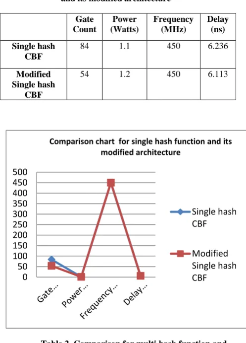
Table 1. Comparison for single hash function and its modified architecture
Gate Count
Power (Watts)
Frequency (MHz)
Delay (ns)
Single hash CBF
84 1.1 450 6.236
Modified Single hash
CBF
54 1.2 450 6.113
[image:4.595.56.277.370.447.2]
Table 2. Comparison for multi hash function and its modified architecture
Gate Count
Power (Watts)
Frequency (MHz)
Delay (ns) Multi-hash
CBF
1551 1.362 440 14.713
Modified Multi hash
CBF
1140 1.310 440 14.644
0 50 100 150 200 250 300 350 400 450 500
Comparison chart for single hash function and its modified architecture
Single hash CBF
[image:4.595.54.281.631.740.2]6.
CONCLUSION
From the results obtained, it is confirmed that the power and delay has been reduced for both single and multi hash CBF. The implementation result shows that the modified single hash and multi hash have 2% and 1.1% reduced delay respectively. The modified multi- hash has 4% reduced power. The gate count required for the single hash A-CBF is 35% less and for multi-hash A-CBF 26% less than the conventional method.
7.
ACKNOWLEDGEMENT
The authors acknowledge the contributions of the faculty of Velalar College of Engineering and Technology for helping in the design of test circuitry, and tool support. The authors also thank the anonymous reviewers for their thoughtful comments that helped to improve this paper. The authors would like to thank the anonymous reviewers for their constructive critique from which this paper greatly benefited.
8.
REFERENCES
[1] www.netsecurity.about.com/cs/hackertools/a/aa030504.h.
[2] Boyer R. S., & Moore J. S. (1977). A fast string searching algorithm. Communications of the ACM, 20, 762–772.
[3] Anagnostakis, K. G., Antonatos, S., Markatos, E. P., & Polychronakis, M. (2003). E2xb: A domain specific string matching algorithm for intrusion detection. In Proceedings of the 18th IFIP international security conference(SEC2003).
[4] Aho, V. A., & Corasick, M. J. (1975). Efficient string
matching:An aid to bibliographic search.
Communications of the ACM, 18, 333–340.
[5] Fisk, M., & Varghese, G. (2002). An analysis of fast string matching applied to content-based forwarding and intrusion detection. In Technical report CS2001-0670 (updated version). San Diego: University of California.
[6] Norton, M., & Roelker, D. (2002). Snort 2.0:
Detectionrevised. http://www.sourcefire.com/.
[7] Fisk, M., & Varghese, G. (2004). Applying fast string matching to intrusion detection. Technical Report CS2001-0670,UCSD.
[8] B. Bloom, “Space/ time trade-offs in hash coding with allowable errors,” Commun. ACM, vol. 13, no. 7, pp. 422-426, July 1970.
[9] Elham Safi, Elham Safi, Andreas Veneris,“L-CBF,A Low-Power,Fast Counting Bloom Filter Architecture” in IEEE Trans. On Very Large Scale Integration (VLSI) systems, Vol. 16, no. 6, June 2008,pp.628-638.
[10] J. K. Peir, S. C. Lai, S. L. Lu, J. Stark, and K. Lai, “Bloom filtering cache misses for accurate data speculation and prefetching,” in Proc. Ann. Int. Conf. Supercomput., Jun. 2002, pp. 189–198.
[11] M. Mitzenmacher and S. Vadhan, “Why simple hash functions work: exploiting the entropy in a data stream,” in Proc. of the 19th annual ACM-SIAM SODA, 2008, pp. 746–755.
[12] M. R. Stan, “Synchronous up/down counter with clock period inde- pendent of counter size,” in Proc. Ann. Symp. Comput. Arithmetic, Jul. 1997, pp. 274–281.
[13] B. S. Amrutur and M. A. Horowitz, “Fast low-power decoders for RAMs,” IEEE J. Solid-State Circuits, vol. 36, no. 10, pp. 1506–1515, Oct. 2001.
[14] B. S. Amrutur, “Design and analysis of fast low power SRAMs,” Ph.D. dissertation, Elect. Eng. Dept., Stanford Univ., Stanford, CA, 1999.
[15] B. S. Amrutur and M. A. Horowitz, “Speed and power scaling of SRAM’s,” IEEE J. Solid-State Circuits, vol. 35, no. 2, pp. 175–185, Feb. 2000.
[16] M. Margala, “Low-power SRAM circuit design,” in Proc. IEEE Work- shop Memory Technol., Design Test., Aug. 1999, pp. 115–122.
[17] P. Alfke, “Efficient shift registers, LFSR counters, and long pseudo- random sequence generators,” Xilinx, San Jose, CA, Appl. Note 052, Jul. 1996.
[18] P. H. Bardell, W. H. McAnney, and J. Savir, Built-in test for VLSI: Pseudorandom techniques. New York: Wiley, 1987.
[19] M. R. Stan, A. F. Tenca, and M. D. Ercegovac, “Long and fast up/down counters,” IEEE Trans. Comput., vol. 47, no. 7, pp. 722–735, Jul. 1998.
[20] H. E. W. Neil and D. Harris, Principles of CMOS VLSI Design, 3rd ed. Reading, MA: Addison Wesley, 2004. 0
200 400 600 800 1000 1200 1400 1600 1800
Comparison chart for multi hash function and its modified architecture
Multi-hash CBF