6
I
January 2018
Study of Performance Enhancement of Half Effect
Vapor Absorption System Using Loop Heat Pipes
Ankit Dwivedi, 1 R S Mishra2
1,2
Dept. of Mechanical Engineering, Delhi Technological University, Delhi
Abstract: The Half Effect Vapor Absorption Refrigeration System (VARS) has performance lower than the Single Effect VARS due to several reasons. This research aims to enhance the performance of the half effect system by incorporation of a Loop Heat Pipe (LHP) between the high absorber, high generator and condenser (which is actually replaced by the LHP) to avail the intra-cycle heat exchange. The simulations show that COP I and COP II increase by 64 % and 27 % respectively. Also the LHP condenser temperature TCondis dependent on the generator temperature TG . At higher temperatures of TG the increase in COP II is more than that in COP I . Average heat leak from the LHP QLeakis around 14.38 kW and average heat utilized due to the LHP QCondis found to be 79.52 kW.
I. INTRODUCTION
[image:2.612.176.459.375.625.2]A half-effect vapour absorption system (Fig 3) consists of 2 generators, 2 absorbers, a condenser, an evaporator, 2 pumps, 2 heat exchangers and 3 throttling valves. The half-effect cycle is basically a combination of two single-effect absorption cycles each working at different pressure levels. This system has been developed for relatively low-temperature heat source application. Also the COP of the half-effect system is relatively lower because it rejects more heat than a single-effect cycle. Heat from high temperature external source, transfers to the generator and the absorbers reject heat to the surroundings.
Fig 1: Cyclic process of a Loop heat pipe [36]
LHPs are self-primed as the volumes of the reservoir, condenser and vapor and liquid lines are controlled so that fluid is always existing to the wick. The reservoir volume and fluid are set to always have fluid in the reservoir even if the condenser and vapor and liquid lines are full of fluid.
[image:3.612.132.479.125.348.2]]
Fig 2: Porous Wick in the LHP.[35]
The LHPs have an inverted wick, and the vapors are located adjacent to the heated surface. These wicks are prepared by power metallurgy. The outer surface of the wick is in contact with the heated surface. Circumferential and axial grooves are required to generate flow channels for the vapors flow which can be machined in the wick, or to the evaporator body.
II. LITERATURE REVIEW
double effect lithium bromide/water absorption refrigeration system. The system consisted of a second effect generator between the generator and condenser of the single effect absorption refrigeration system, including two solution heat exchangers between the absorber and the two generators. S.C. Kaushik et al. (2009) presented the energy and exergy analysis of single effect and series flow double effect water–lithium bromide absorption systems. They developed a computational model for the parametric investigation of the systems. Berhane H. Gebreslassie et al. (2010) performed an exergy analysis, which only considered the unavoidable exergy destruction, conducted for single, double, triple and half effect Water–Lithium bromide absorption cycles. Gulshan Sachdeva et al.(2014) performed an exergy analysis of VAR system using LiBr-H2O as working fluid with the modified Gouy-Stodola approach. Karl Ochsner (2008)et al. (2008) developed a new CO2-heat pipe with high-grade steel corrugated pipe system, which – contrary to other pipe systems permits raw length up to 100 m. They also described the establishment of the heat pump system in general.There are different sorts of the VARS namely half, single, double, triple effects etc. Thorough study of the research papers it can be observed that rigorous thermodynamic and thermo-economic studies have already been performed on almost all of the possible systems. The ground work for further improvements in the systems has also been created. Some other components can be brought in the system and some further enhancements in the performance can be brought in.In the research work LHP can be used as the new component for intra-cycle heat exchange and reduce the requirement of heat input for the cycle to operate. Also replacements of other bulky components can be done by the LHP, which would reduce the cost and size of the system
III. SYSTEMS DESCRIPTION
[image:4.612.88.532.371.659.2]Figure 3 shows a schematic of Half Effect VARS which is working between 100ºC and 5°C. As the simulation shows the half effect cycle has lower COP I& COP II than the single effect cycle, one can apply some modifications to improve the performance of the half effect cycle. The refrigeration capacity of the cycle is set to be 90 kW and the working fluid can be NH3-H2O solution. The system consists of 2 generators, absorbers and heat exchangers.
Fig 3: A Half Effect Vapour Absorption System
also be a LHP used between the High absorber and Low Generator similar to the arrangement that will reduce the heat requirements in low generator. The table 1 has the list of the terms used in the research work.
Fig.4: Modified Half Effect Vapour Absorption System
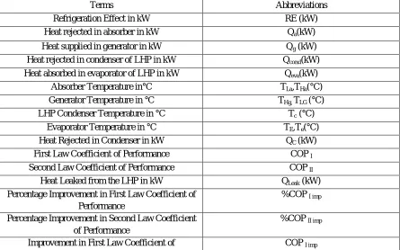
Table 1: Terms Used in Simulation
Terms Abbreviations
Refrigeration Effect in kW RE (kW)
Heat rejected in absorber in kW Qa(kW)
Heat supplied in generator in kW Qg (kW)
Heat rejected in condenser of LHP in kW Qcond(kW)
Heat absorbed in evaporator of LHP in kW Qeva(kW)
Absorber Temperature in°C TLa,THa(°C)
Generator Temperature in °C THg, TLG (°C)
LHP Condenser Temperature in °C Tc (°C)
Evaporator Temperature in °C TE,Te(°C)
Heat Rejected in Condenser in kW QC (kW)
First Law Coefficient of Performance COP I
Second Law Coefficient of Performance COP II
Heat Leaked from the LHP in kW QLeak (kW)
Percentage Improvement in First Law Coefficient of Performance
%COP I imp
Percentage Improvement in Second Law Coefficient of Performance
%COP II imp
[image:5.612.84.529.447.725.2]Performance
Improvement in Second Law Coefficient of Performance
COP II imp
IV. RESULTS AND DICSUSSIONS
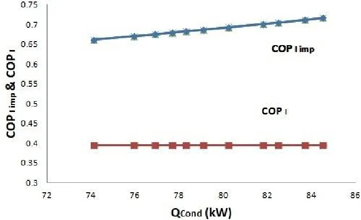
[image:6.612.129.493.205.427.2]The simulations show the following results. Fig 5 & Fig 6 show the improvements in COP I and COP II with varying heat utilized in the condenser of LHP (QCond) with reference to the performance of the system without modifications. It can be inferred from the Fig 5 that the improvements in COP I is directly proportional to the heat being utilized. The average improved COP I ,that the simulations show, is around 0.69.
[image:6.612.137.488.460.706.2]Fig 5: Comparison between COP I and COP I imp plotted with QCond
The Fig 6 shows that with reuse of heat in the LHP decreases the loss of exergy increasing the COP II . The COP II decreases a little but then it rises steadily similar to the COP I . Also the heat transfer at high temperatures helps in decreasing the exergy loss. The average enhanced COP II has been calculated to be 0.502 .
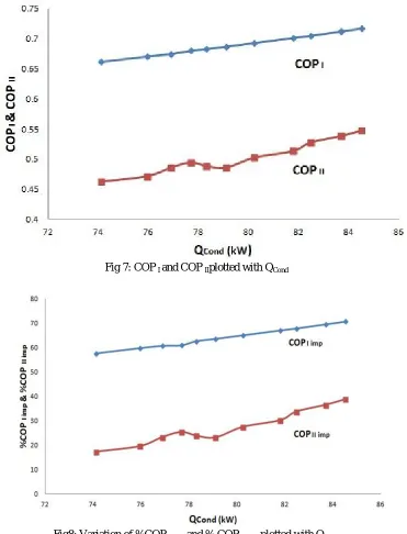
[image:7.612.127.498.148.634.2]Moreover the Fig 7 and Fig 8 show the relative comparison between the COP I&COP II .Fig 7 shows the comparison between the COP I and COP II with the varying QCond. Both rise steadily for the entire range of the QCond.
Fig 7: COP I and COP IIplotted with QCond
Fig8: Variation of %COP I imp and % COP II imp plotted with QCond
The fig 8 shows the percentage improvement in the COP I and COP II with QCond.The average rise in the COP I is 64 %, where as that in COP II is 27 %. In both the figures, COP I and COP II the rise is parallel.
Fig9: Comparison of %age improvements in COP I& COP II varying the TC
[image:8.612.136.493.524.721.2]Fig 10: Comparison of %age improvements in COP I& COP II varying the TG
Fig 12: Comparison of COP I& COP II varying the TC
The Fig 13 & Fig 14 show the values of QCond&QLeakwith respect TC and TG. With increase in the temperatures the heat leaked from the LHP is found to reduce, whereas the heat reusable increases.
[image:9.612.132.496.402.724.2]The TC is a dependent parameter on TG directly. As the TG increases the Tc also increases the heat to be supplied and the maximum temperature up to which it can be transferred also increases. The average QCondis observed to be 79.52 kW.
Fig 14: Comparison of QLeak&QCondvarying the TG
QLeakis found to decrease as the operating temperature increases. The operating temperature increases the heat transfer coefficient hence more heat is transferred in the evaporator of the LHP, reducing the QLeak. The average QLeak is calculated to be 14.38 kW.
V. CONCLUSIONS
Through the simulations followings can be the conclusions for the Half Effect VARS:
A. COP I& COP II increase with the QCond and the average values for the modified value are 0.69 & 0.502 respectively. B. The average rise in the COP I is 64 %, where as that in COP II is 27 %.
C. Higher the TG, higher will be the TC. With high temperatures of heat exchange, the COP II rise is more than the rise in COP I . Whereas the rise in COP I becomes flat.
D. With increase in the temperatures the heat leaked from the LHP is found to reduce. Average QLeakis around 14.38 kW.
E. The operating temperature increases the heat transfer coefficient hence more heat is transferred in the evaporator of the LHP having the average QCondas 79.52 kW.
F. The exergetic losses can be reduced, along with the reduction in size of the system, making the system flexible.
REFERENCES
[1] Saeed. Sedigh , Hamid. Saffari ,”Thermodynamic analysis of single effect and half effect absorption refrigeration system” International Journal of Energy & Technology Vol.25 (2011) 1-9.
[2] S. Arivazhagan , R. Saravanan , S. Renganarayanan ,” Experimental studies on HFC based two-stage half effect vapour absorption cooling system” Applied Thermal Engineering Vol. 26 (2006) 1455–1462.
[3] GulshanSachdeva, Ram Bilash,” Thermodynamic Analysis of a Vapor Absorption System Using Modified Gouy-Stodola Equation” International Journal of Computer, Electrical, Automation, Control and Information Engineering Vol:8, No:12, 2014.
[4] I. Horuz,” A comparison between Ammonia-water and Water-Lithium Bromide solutions in Vapor Absorption Refrigeration Systems” Int. Comm. Heat Mass Transfer, Vol. 25, No. 5, pp. 711-721, 1998.
[5] Abdul Khaliq, and Rajesh Kumar,” Exergy analysis of double effect vapor absorption refrigeration system” Int. J. Energy Res. 2008; Vol.32:161–174. [6] S.C. Kaushika, AkhileshArora,” Energy and exergy analysis of single effect and series flow double effect water–lithium bromide absorption refrigeration
systems” international journal of refrigeration Vol.32 ( 2009 ) 1247 – 1258.
[7] RabahGomri , RiadHakimi,” Second law analysis of double effect vapour absorption cooler system” Energy Conversion and Management Vol.49 (2008) 3343– 3348.
[9] RabahGomri,” Second law comparison of single effect and double effect vapour absorption refrigeration systems” Energy Conversion and Management Vol. 50 (2009) 1279–1287.
[10] R.D. Misra, P.K. Sahoo, S. Sahoo, A. Gupta,”Thermoeconomic optimization of a single effect water/LiBrvapour absorption refrigeration system” International Journal of Refrigeration Vol.26 (2003) 158–169.
[10] M. Belghazi, A. Bontemps, C. Marvillet,” Experimental study and modelling of heat transfer during condensation of pure fluid and binary mixture on a bundle of horizontal finned tubes” International Journal of Refrigeration Vol.26 (2003) 214–223.
[11] M.M. Talbi, B. Agnew,” Exergy analysis: an absorption refrigerator using lithium bromide and water as the working Fuids” Applied Thermal Engineering Vol. 20 (2000) 619-630.
[12] E. Kurem,” A comparison between Ammonia-water and Water-Lithium Bromide solutions in vapour absorption heat transformers “In. Comm. Heat Mass Transfer; Vol. 28, No. 3, pp. 421-438, 2001.
[13] Da-Wen Sun,” Comparison of the performances and NH3-H20, NH3-LiNO3 and NH3-NaSCN Vapor Absorption Refrigeration Systems” Energy Convers. MgmtVol. 39, No. 5/6, pp. 357-368, 1998.
[14] Yu.F. Maydanik,” Review Loop heat pipes” Applied Thermal Engineering Vol.25 (2005) 635–657.
[15] Randeep Singh, AliakbarAkbarzadeh , MasatakaMochizuk,” Operational characteristics of a miniature loop heat pipe with flat evaporator” International Journal of Thermal Sciences Vol.47 (2008) 1504–1515.
[16] T.X. Li, R.Z. Wang , L.W. Wang, Z.S. Lu, C.J. Chen,” Performance study of a high efficient multifunction heat pipe type adsorption ice making system with novel mass and heat recovery processes” International Journal of Thermal Sciences Vol.46 (2007) 1267–1274
[17] Yuan-Ching Chiang , Wen-Cheng Kuo , Chia-Che Ho , Jen-JieChieh,” Experimental study on thermal performances of heat pipes for air-conditioning systems influenced by magnetic nanofluids, external fields, and micro wicks” International Journal of Refrigeration Vol.43 ( 2014 ) 62 -70.
[18] T.X. Li, R.Z. Wang, L.W. Wang, Z.S. Lu,” Experimental investigation of an innovative dual-mode chemisorption refrigeration system based on multifunction heat pipes” International Journal of Refrigeration 3 1 ( 2 0 0 8 ) 1 1 0 4 – 1 1 1 2.
[19] L. GarousiFarshi a,*, C.A. Infante Ferreira b, S.M.S. Mahmoudi a, M.A. Rosen,” First and second law analysis of ammonia/salt absorption refrigeration systems” International Journal of Refrigeration Vol. 4 0 ( 2 0 1 4 ) 1 1 1-1 2 1.
[20] T.X. Li, R.Z. Wang , L.W. Wang, Z.S. Lu, J.Y. Wu,” Influence of mass recovery on the performance of a heat pipe type ammonia sorption refrigeration system using CaCl2/activated carbon as compound adsorbent” Applied Thermal Engineering Vol. 28 (2008) 1638–1646.
[21] Z.S. Lu , L.W. Wang, R.Z. Wang,” Experimental analysis of an adsorption refrigerator with mass and heat-pipe heat recovery process” Energy Conversion and Management Vol. 53 (2012) 291–297.
[22] Behrooz M. Ziapour*, Mohsen Tavakoli,” Performance study on a diffusion absorption refrigeration heat pipe cycle” International Journal of Thermal Sciences Vol.50 (2011) 592-598.
[23] Basant K. Agrawal*, Munawar N. Karimi,” Thermodynamic performance assessment of a novel waste heat based triple effect refrigeration cycle” International Journal of Refrigeration Vol. 3 5 ( 2 0 1 2 ) 1 6 4 7-1 6 5 6.
[24] Behrooz M. Ziapour*, Mohsen Tavakoli,” Performance study on a diffusion absorption refrigeration heat pipe cycle” International Journal of Thermal Sciences 50 (2011) 592-598.
[25] T.S. Jadhav , M.M. Lele,” Theoretical energy saving analysis of air conditioning system using heat pipe heat exchanger for Indian climatic zones” Engineering Science and Technology, an International Journal Vol. 18 (2015) 669-673.
[26] Chengchu Yan , Wenxing Shi , Xianting Li , Shengwei Wang,” A seasonal cold storage system based on separate type heat pipe for sustainable building cooling” Renewable Energy Vol.85 (2016) 880-889.
[27] Matthias H. Buschmann,” Nanofluids in thermosyphons and heat pipes: Overview of recent experiments and modelling approaches” International Journal of Thermal Sciences Vol.72 (2013) 1-17.
[28] P.D. Dunn, D.A. Reay, Heat Pipes, Pergamon Press, Oxford, 1993.
[29] D.Reay, Heat Pipes-Theory, Design and Applications, Butterworth-Heinemann,Oxford, Fifth edition 2006.
[30] Korn, F., “Heat Pipes and its Applications” Project Report 2008 MVK160 Heat and Mass Transport May 07, 2008, Lund, Sweden.
[31] Rajashree, R., Rao, K.S., “A Numerical Study of the Performance of Heat Pipe” Indian Journal of Pure and Applied Mathematics, 21 (1): 95-108, January 1990.
[32] C.P. Arora, Refrigeration and Air Conditioning, Tata Mcgraw-Hill Publishing Company Limited,Delhi, Third Edition, 2009.
[33] AnkitDwivedi, R. S. Mishra,” Thermodynamic Analysis of Heat Pipe Using Ammonia, Water and Ethanol with a View to Being Used in Refrigeration” ISSN 2347 - 3258 International Journal of Advance Research and Innovation, Volume 3, Issue 3 (2015) 498-502.
[34] AnkitDwivedi, R. S. Mishra, Manjunath K,”Optimization of Vapour Absorption System Using Heat Pipes” ISSN: 2321-9653 International Journal for Research in Applied Science & Engineering Technology (IJRASET), Volume 5 Issue VIII, August 2017,634-639.
![Fig 1: Cyclic process of a Loop heat pipe [36]](https://thumb-us.123doks.com/thumbv2/123dok_us/8295998.852876/2.612.176.459.375.625/fig-cyclic-process-loop-heat-pipe.webp)
![Fig 2: Porous Wick in the LHP.[35]](https://thumb-us.123doks.com/thumbv2/123dok_us/8295998.852876/3.612.132.479.125.348/fig-porous-wick-in-the-lhp.webp)