5
IV
April 2017
Technology (IJRASET)
Study Paper on Methods of Measurement of
Residual Stress in Mechanical Components
Mr. Vikas Dive1, Ms. Snehal Lasurkar2, Mr. Kishor Limaje3, Mr. Kumar Yash4
Department of Mechanical Engineering
Dr. D. Y. Patil Institute of Engineering, Management and Research, Akurdi, Pune-44, India
Abstract: Now a days study of residual stress is becoming more important as they influences the fatigue behavior and breaking strength of the mechanical component and even its corrosion resistance. The residual stresses can cause extensive dimensional changes, most of the times they are introduce intentionally as they can be beneficial. Therefore it becomes necessary to measure the distribution of residual stresses. Various methods are available for measurement of residual stress. The information regarding residual stresses is already been widely available .This paper aims to advise or suggest the available method for measurement of residual stresses.
Keywords: residual stress,distructive method, deep hole drilling method, incrimental hole drilling method
I. INTRODUCTION
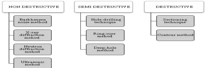
During manufacturing of Mechanical components various stress are generated. This stress may be desirable or undesirable. Most of the time these stresses are responsible for failure of mechanical components. Hence residual stress analysis is an important stage while designing the mechanical components. During analysis, various methods are available such as destructive (counter method, sectioning technique), semi destructive (hole drilling, deep hole drilling) and non-destructive (x-ray diffraction , neutron diffraction).
II. DEFINATIONOFRESIDUALSTRESS
Residual stresses can be define as the stresses that remain in mechanical component during manufacturing process after the original stresses has been removed. They can also be produced by service loading.
III. CAUSE OF RESIDUAL STRESS
Residual stresses are generated during most manufacturing processes involving material deformation, heat treatment, machining or processing operations that transform the shape or change the properties of a material. They are originated from a number of sources and can be present in the mechanical component, introduced during manufacturing or arise from in-service loading.
IV. CLASSIFICATION OF RESIDUAL STRESS MEASURING METHODS
[image:2.612.142.483.591.704.2]Many techniques exist for the measurement of residual stresses within engineering components; however it is the effects of the residual stresses that are actually measured not the stresses themselves. The destructive techniques are also known as Mechanical Strain Release (MSR) techniques.
Destructive technique includes following methods
1) Sectioning Technique: Measurement of residual stresses by the sectioning method has been used for decades to measure residual stresses in structural members. This method has proven itself adequate, accurate and economical if proper care is token in the preparation of the specimen and the procedure of measurement. However, a standard procedure to carry out such measurement does not exist in the published literature. In this paper, o detailed description is presented on the procedure of testing, preparation of specimen, the required tools and measuring devices and working conditions. For a specific cornparision of results, measurements of residual stresses were performed on a specimen having a uniform residual stress distribution along its length..The sectioning method consists in making a cut on an instrumented plate in order to release the residual stresses that were present on the cutting line. For this, the cutting process used should not introduce plasticity or heat, so that the original residual stress can be measured without the influence of plasticity effects on the cutting planes’ surface.
2) Contour Method: This method measures the residual stress on a 2 plane section through a specimen, in a uniaxial direction normal to a surface cut through the specimen with wire EDM.
At present the technique can readily measure residual stresses across sections greater than 5 mm thick and welded structures where the microstructure varies. It is increasingly being applied to map residual stresses in components to support structural integrity assessments, validate process models including weld simulation and underwrite new manufacturing routes across diverse industry sectors nuclear, power generation, aerospace, petrochemical and transport).
The method involves making a straight cut in the sample of interest along a plane where knowledge of residual stresses is required. The created cut surfaces locally deform owing to the relaxation of residual stresses present before the cut. These deformations are measured and then applied as a boundary condition in a finite element model to determine the out-of-plane residual stress distribution at the cut surface.
B. Semi Destructive Technique
Similarly to the destructive techniques, these also function using the "strain release" principle. However, they remove only a small amount of material, leaving the overall integrity of the structure intact. These include:
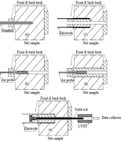
1) Deep Hole Drilling Method: Deep-hole drilling (DHD) is a technique that allows the measurement of residual stress fields through very thick components. The main assumption of this method is that the drilling of the reference hole has no effect on the residual stress state and that removing the core causes the residual stresses around the hole to be fully released in an elastic manner. The deep hole drilling technique has usually been used on metal parts such as in welds and railway tracks. In metallic components, EDM can be used to trepan a central core around the reference hole since the cutting stresses introduced by this method are not significant. The hole-drilling method involves three major aspects:
First a reference hole is drilled through the thickness of the specimen using a self-aligning gun drill
The diameter of the reference hole is measured accurately using an air probe at different angles around the reference hole and at equal intervals through the thickness of the sample
Then a core coaxial to the reference hole is trepanned using an electro discharge machining in metallic components.
Technology (IJRASET)
Fig. 1 A schematic diagram illustrating the procedures in the deep hole drilling technique: a) drill reference hole; b) diametral measurement of the reference hole; c) trepanning; re-measure the reference hole; e) axial strain measurement.
2) Incremental Hole Drilling Method: The incremental hole-drilling method is a widely used technique to determine residual stress depth profiles in technical components. Its application is limited in respect to the components geometry, for instance the components thickness. In this paper, a direct correction of the measured strain relaxations is proposed to consider the impact of deviant geometries, here the component thickness, on the residual stress evaluation that moreover, allows the application of commercially available evaluation software. The here in proposed approach is based on finite element simulation of the incremental hole drilling. The simulated strain relaxations for thin metal sheets are evaluated with an algorithm as used in commercially available evaluation software (i) for uncorrected data as well as (ii) for strain data corrected by the proposed correction procedure. It is shown that the correction approach leads to a significant improvement of the measurement accuracy. Further, by means of the approach residual stress depth profiles in thin metal sheets can be as usual determined using commercial evaluation software for the incremental hole-drilling method regardless of the algorithm used, i.e. differential or integral.
Neutron diffraction has some unique characteristics when compared to other types of radiation. This makes it very useful for the study of the atomic structure of liquids, amorphous materials and crystalline materials. Diffraction can see the ordered part of systems, which means, for ordered systems (crystals), their average structure but also deviations from this perfect order; for disordered systems, the ordered portions existing amid this disorder.
2) X-Ray Diffraction: The X-ray Diffraction (XRD) technique is the most widely used non-destructive technique, specialising in the measurement of surface residual stresses. Using laboratory-based or portable equipment, the XRD technique measures
surface residual stresses to depths of up to 30μm by measuring the material's inter-atomic spacing. The X-ray method is a non-destructive technique for the measurement of residual stresses on the surface of materials. X-ray diffraction techniques exploit the fact that when a metal is under stress, applied or residual stress, the resulting elastic strains cause the atomic planes in the metallic crystal structure to change their spacings. X-ray diffraction can directly measure this inter-planar atomic spacing; from this quantity, the total stress on the metal can then be obtained.
3) Ultrasonic Method: Ultrasonic waves (2 MHz - 10 MHz) are commonly used to detect flaws in engineering materials; however they can also be used for the measurement of stresses, applied and residual. The speed of ultrasonic waves travelling through a material are affected by the direction and magnitude of the stresses present, which is called the acoustoelastic effect. Therefore the magnitude and direction of the stresses present within a material can be calculated by accurately measuring the change in time-of-flight of an ultrasonic wave traveling through the stressed and unstressed regions of that material. For example, a stress of 1MPa in aluminium corresponds to a change in time-of-flight of roughly 1.7 ns. The acoustoelastic effect is most sensitive when the propagation path and particle motion of the ultrasonic wave are parallel to the direction of stress being measured. Different configurations of ultrasonic equipment can be used for residual stresses measurements. Overall, waves are launched by a transmitting transducer, propagate through a region of the material, and are detected by a receiving transducer. The technique in which the same transducer is used for excitation and receiving of ultrasonic waves is often called the pulse echo method. This method is effective for the analysis of residual stresses in the interior of the material. In this case the through thickness average of the residual stresses is measured. The depth of this layer is related to the ultrasonic wave-length, often exceeding a few millimetres, and hence is much greater that obtained by X-ray method. Other advantages of the ultrasonic technique are the facts that instrumentation is convenient to use, quick to step up, portable, inexpensive, and free of radiation hazards.
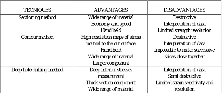
[image:5.612.80.533.483.675.2]D. Comparison of the Residual Stresses Measurement Techniques
Table 1 Comparison of the residual stresses measurement techniques.
TECNIQUES ADVANTAGES DISADVANTAGES Sectioning method Wide range of material
Economy and speed Hand held
Destructive Interpretation of data Limited strength resolution Contour method High resolution maps of stress
normal to the cut surface Hand held Wide range of material
Larger component
Destructive Interpretation of data Impossible to make successive
slices close together
Deep hole drilling method Deep interior stresses measurement Thick section component
Wide range of material
Interpretation of data Semi destructive Limited strain sensitivity and
Technology (IJRASET)
Incremental hole drilling Fast Easy use Generally available
Hand held Wide range of material
Interpretation of data Semi destructive Limited strain sensitivity and
resolution
Neutron diffraction Micro and macro RS Optimal penetration and
resolution 3D maps
Only Ferro magnetic materials Need to divide the micro structure
signal from that due to stress
X-ray diffraction Ductile Generally available Wide range of material available
Hand held system Micro and macro RS
Lab base system Small components Only basic measurement
Ultrasonic method Generally available Very quick
Low cost Hand held
Limited resolution Bulk measurement over whole
volume
V. SUMMARY
The paper provide an overview of the different residual stress measurement techniques available and guide the Engineer towards key points of technique for further and more in-depth reading. Also provided the comparison of technique and also the favourable condition in which this techniques can be used. Table advantages and disadvantages of destructive, semi destructive and non destructive methods are listed in this paper. Also we have studied different method available for measurement in destructive, semi destructive and non destructive method. This paper will provide information regarding technique selection and method selection while measuring the residual stress in mechanical component.
REFERENCES
[1] N.S. Rossini , M. Dassisti , K.Y. Benyounis , A.G. Olabi ., “Methods of measuring residual stresses in components” , Materials and Design 35 (2012) 572–588
[2] F.Hosseinzadeh, A.H.Mahmoudi, C.E.Truman and D.J.Smith , “ Prediction and Measurement of Through Thickness Residual stresses in Large Quenched
Components ” Proceedings of the World Congress on Engineering 2009 Vol II WCE 2009, July 1 - 3, 2009, London, U.K. Online articles
[3] http://www.veqter.co.uk/residual-stress-measurement/overview [4] http://www.veqter.co.uk/residual-stress-measurement/deep-hole-drilling. [5] http://www.protoxrd.com/residual-stress-info.html