Journal of Chemical and Pharmaceutical Research, 2015, 7(4):463-470
Research Article
CODEN(USA) : JCPRC5
ISSN : 0975-7384
Comparative study of the optimum controller selection for control
distillation column level in Khartoum Refinery
Salah Eldeen F. Hegazi
1, Gurashi Abdallah Gasmelseed
2,
Mubarak A. Aldoma
3and
Mohammed M. Bukhari
41Department of Chemical Engineering, Faculty of Engineering, Jazan University, Saudi Arabia
2Department of Chemical Engineering, Faculty of Engineering, University of Science & Technology, Sudan
3
Department of Chemical Engineering, Faculty of Engineering, Jazan University, Saudi Arabia
4Department of Chemical Engineering, Faculty of Engineering, University of Bengahzi, Libya
_____________________________________________________________________________________________
ABSTRACT
The delayed coking unit in Khartoum Refinery is using cascade control technique for controlling the bottom level of the Coker fractionator, A temperature in the stripping section is held by steam to the reboiler. Situation may arise where the base level continues to drop even with the valve of the bottom flow is fully closed, this is due to the fact that the boil rate is greater than the liquid condensation rate which means that the rate of the steam to the reboiler is very high. It is required to control this critical situation by cascade control technique. MATLAB tool box consider as the main software used in the analysis the control loop of the delayed coking unit . The graphical user inter-phase (GUI) tool box helps in obtaining the transfer function for the coker fractionator which leads to complete analysis using Simulink in continuous, frequency domain and digital system. Unit Step applied to the transfer function which results in finding the final value = -0.02, the offset = -1.02 and settling time =7.71 sec. Different tuning methods were applied for the system to find the ultimate gain and Ziegler-Nichol table used for the recommended values. The roots locus method is preferable compared to other methods for the least deviation
from the a average values which results in Kc=0.15,τI=1.3335min, τD =0.33 min
Key words: Coker; Transfer function; Simulink ; Setting time; Frequency; Ultimate gain
_____________________________________________________________________________________________
INTRODUCTION
In chemical plants and petroleum refineries, there are, today, many distillation columns that are working well. There are also many others that are not working well, and at least a few that function very poorly, or not at all. Failure to obtain performance specified by the column design engineer is due, in many cases, to faulty or inadequate control system design. Troubleshooting of columns that are already in operation is frequently necessary, but practical considerations usually limit corrective measures to relatively minor items. Proper original design is by far the best way to guarantee satisfactory operation and control [1].
Therefore, we will approach the design of integrated distillation column control systems as a systems problem in process design. The application of feed forward, feedback, and protective controls will be coordinated with the sizing and proper location of process holdups [1].
1.1 The delayed coking process
The processing of low quality crudes is more frequent than ever and the heavy Feedstock is providing high quantities of vacuum residue. The delayed coking unit is the main converter of residue and usually a refinery that owns a Coker is considered to be residual free. Our work investigates the delayed coking process due to the new environmental conditions for end products and because economic optimization based on model advanced control is required for plant flexibility. During the last few years a new trend of processing heavy crudes appeared because of their prices and availability, despite all the problems generated by the procedure. The delayed coking is one of the few processes able to convert heavy products (atmospheric and vacuum residues) into lighter ones with high economic value: gases C1 – C3, gasoline, gas oil, heavy distillate and coke. [3], [4].
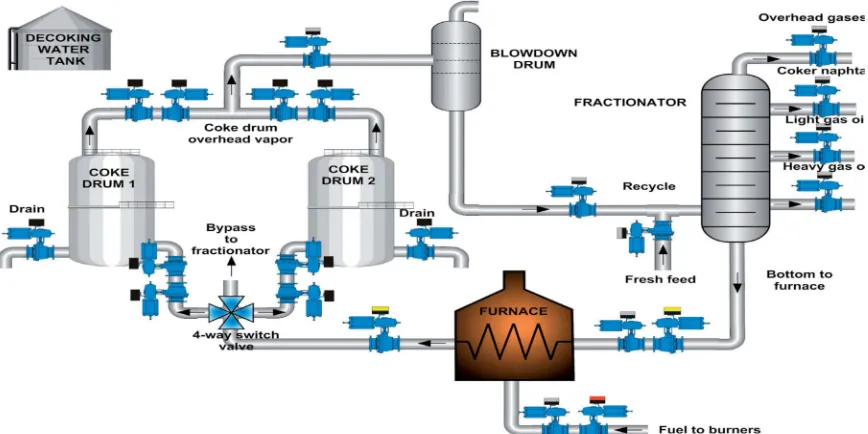
[image:2.595.76.510.302.519.2]Figure 1 is a schematic representation of a delayed coking unit from a Khartoum refinery. The vacuum residue (1) represents the fresh feed (al-fula crude) which is heated up in the convection zone of the furnace (CF) at 315-320oC and then it is inserted at the bottom of the fractionator (F). Here, some lighter fractions are removed as side streams and the mixed feed from the fractionator’s bottom is redirected to the radiation section of the furnace (CF), where it is heated up to a high cracking temperature (490-495o C). In order to avoid the coke deposition on radiation tubes, high pressure steam is introduced in the furnace tubes. The outcome of the radiation section of the furnace is a partially cracked product which enters the coke drums (CD) where cracking continues. Each drum is filled with coke for approximately 20 hours, depending on the input flow and CCR (Conradson carbon residue). The remaining coke is periodically removed from the drum [3].
Figure 1: A schematic representation of a delayed coking unit
EXPERIMENTAL SECTION
Data were taken from Khartoum Refinery, the table below shows the corresponding values of bottom level of the coker’s fractionator and furnace flow rates
Table (1): Operating records for Column Bottom level& Furnace flow rate
Flow rate-convection(T/h) Column bottom level%
114 65
114 65
113 69
112 68
112 68
112 50
113 50
113 50
[image:2.595.192.387.619.719.2]via system identification by the graphical user interface (GUI) was used for predicating the model and the transfer function of the cascade control which considered as the key of the control system analysis and different tuning methods used for investigation the system stability[5],[6].
2.2 Transfer Function
The model developed using system identification tool box (Graphical user Interface GUI) from MATLAB helps for obtaining transfer function relates the bottom level against the furnace flow rates in the S-domain and in Z-domain [7],[8].
The Transfer function in Z-domain:
G . . . . . (1)
The transfer function converted using MATLAB commands into S-domain G . . . .. (2)
2.2.1 Offset Final Value: C(∞)=lim s C (3)
r(t) =1.0 (4)
R(s) = (5)
C 1S 1.402S ! 3.967 S & 0.05113S ! 1.018 S ! 2.349 ) *6+
C(∞) ,-./ 0/C (7)
C(∞) 1 . . . . . 2 (8)
C(∞) = -0.02 Fot the ideal response is unity .Hence Cid =1.0 (9)
Offset; ε= Cω - Cid (10)
Offset = -0.02 – 1 = -1.02 From the characteristic equation 0.43 (11)
Comparing with the characteristic equation
= τ 0.66 ;
= τ ξ2 0.43,
So ξ=0.33 and the system at this value is under damped.
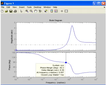
Fig. (2): Response of the system due to unit step
2.2.2 Tuning Methods
Tuning of the bottom level of the Coker’s fractionator investigated using different methods: a) Ziegler-Nichol b)Bode Criteria c) Nyquist Criteria d) Roots Locus and Routh Criteria
[image:4.595.97.492.66.353.2] [image:4.595.103.479.457.757.2]Fig.(4): Ziegler-Nichol for controlling bottom level
Fig.(6): Roots-Locus for controlling bottom level
RESULTS AND DISCUSSION
3.1 The results
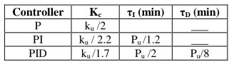
[image:6.595.101.483.70.332.2]The critical values were found using different analysis technique: Routh test, Nyquist, Bode and roots locus method. Then table 1 used to find the gain and integral time and derivative time for different types of controller suggested.
Table 1: Z.N recommended setting for feedback controller
Controller Kc τI (min) τD (min)
P ku /2 ___
PI ku / 2.2 Pu /1.2 ___
PID ku /1.7 Pu /2 Pu/8
Table (2): Comparison between Ziegler- Nichols ,Bode, Nyquist, Roots Locus and Routh methods
[image:6.595.208.372.453.498.2] [image:6.595.183.396.521.681.2]Table (3): Deviation values of proportional gain from average values for P-
Kc - k*c|
Kc Method 0.28 0.21 Ziegler-Nichols 0.49 0.985 Bode Method 0.49 0.985 Nyquist Method 0.36 0.128 Roots Locus 0.37 0.125 Routh Criteria
K*c=0.49 Average Value
Table (4): Deviation from average values for PI-Controller
τI - τ*I|
τI Kc-k*c kc Method 2.34 3.3 0.24 0.19 Ziegler-Nichols 3.75 9.39 0.45 0.88 Bode Method 3.75 9.39 0.45 0.88 Nyquist Method 1.77 3.87 0.32 0.11 Roots Locus 3.39 2.25 0.32 0.11 Routh Criteria 5.64 0.43 Average value
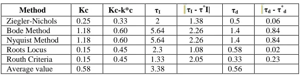
Table (5): Deviation values of Constant time from average values for PID
τd - τ*d τd
τI - τ*I| τI Kc-k*c Kc Method 0.06 0.5 1.38 2 0.33 0.25 Ziegler-Nichols 0.84 1.4 2.26 5.64 0.60 1.18 Bode Method 0.84 1.4 2.26 5.64 0.60 1.18 Nyquist Method 0.02 0.58 1.08 2.3 0.45 0.15 Roots Locus 0.23 0.33 2.05 1.33 0.45 0.15 Routh Criteria 0.56 3.38 0.58 Average value 3.2 Discussion
The root locus method is a very useful graphical technique for identifying the roots of the characteristic equation:
The roots locus method result is the minimum deviation compared to other different methods. The deviation using PID controller for the proportional gain = 0.45 from the average value, the deviation in the integral time=1.08 from the average value and the derivative time =0.02 from average value.
CONCLUSION
From an economic point of view, the delayed coking process is a valuable solution to the problem of decreasing residual fuel demand. It also generates a variety of fuels and in some cases a considerable amount of high quality coke (needle while eliminating environmentally unfriendly streams that often involve a disposal cost. Implementing advanced process control on a coking plant is quite a difficult task but the results could be remarkable: energy savings, maximized throughput, decreased CO emissions and improved yields while increasing the overall profit of the refinery.
Recommendation
The application of the override is essential for controlling the base level so recommend to adopt override control especially for the base level due to dangerous situation when the level goes below the set point which leads to dry the column, further the control protect the column from this situation.
The roots Locus method is preferable method for tuning and controlling base level of the coker’s fractionator.
Acknowledgements
The authors wish to thank the Faculty of Graduation Studies in Gezira University, and Khartoum Refinery Company for their help and support this Paper.
REFERENCES
[1] Willian L.Luyben; Josph P.Shunta. Design of distillation column control systems, Engineering Department-Lehigh University ,creative service s Inc., New York ,1985
[2] Sean Goodhart, Haseloff V., Friedman Y.Z. Implementing coker advanced process control, Hydrocarbon Processing, June 2007,99-103
[image:7.595.214.367.89.163.2] [image:7.595.139.441.289.367.2][4] Al-Haj Ibrahim, H. and Ali,M,M. The arabian Journal for science and engineering ,2005, l30-28
[5] Jim McLellan,”Using Matlab and the System Identification Toolbox to Estimate Time Series Models ,February2004
[6] Gurshi A.Gasemseed. “Advance Control Systems text book”,2011 [7] Ljung, L. System Identification Toolbox.,The Mathworks Inc.,1991
[8] Martin Hill .Identification &Optimization PID parameters Using MATLAB, Report of the project for Bachelor of Engineering in Electronics Cork Institute of Technology-Gdynia Maritime University,2002