Surface Roughness and Tool Wear on Cryogenic Treated
CBN Insert on Titanium and Inconel 718 Alloy Steel
S Thamizhmanii1*, R Mohideen1, A M A Zaidi2 and S. Hasan3**
1International College of Automotive,
Peramu Jaya, 26607, Pekan, Pahang, Malaysia.
2Universiti Pertahanan Nasional Malaysia (UPNM),
Kem Sungai Besi, 57000, Kuala Lumpur, Malaysia.
3University Tun Hussein Onn Malaysia,
Parit Raja, Batu Pahat, Malaysia.
*email: [email protected] and **email:[email protected]
Abstract: Machining of materials by super hard tools like cubic boron nitride (cbn) and poly cubic boron nitride (pcbn) is to reduce tool wear to obtain dimensional accuracy, smooth surface and more number of parts per cutting edge. wear of tools is inevitable due to rubbing action between work material and tool edge. however, the tool wear can be minimized by using super hard tools by enhancing the strength of the cutting inserts. one such process is cryogenic process. this process is used in all materials and cutting inserts which requires wear resistance. the cryogenic process is executed under subzero temperature -186º celsius for longer period of time in a closed chamber which contains liquid nitrogen. in this research, cbn inserts with cryogenically treated was used to turn difficult to cut metals like titanium, inconel 718 etc. the turning parameters used is different cutting speeds, feed rates and depth of cut. in this research, titanium and inconel 718 material were used. the results obtained are surface roughness, flank wear and crater wear. the surface roughness obtained on titanium was lower at high cutting speed compared with inconel 718. the flank wear was low while turning titanium than inconel 718. crater wear is less on inconel 718 than titanium alloy. all the two materials produced saw tooth chips.
1. Introduction
2
[image:2.595.158.434.154.313.2]milling of medium carbon steel. The cryogenically treated inserts exhibit better tool wear resistance than untreated.
Figure 1.
High-speed cutting ranges in machining of various materials
[1]
2. Experimental Setup
2.1. Principle of deep cryogenic treatment
In this research, CBN inserts were cryogenically treated and the process is explained briefly. Cryogenic expresses study and use of materials at very low temperature, below – 186º Celsius. Liquid Nitrogen (LN) is the most commonly used element in cryogenics. Nitrogen melts at -201.01º Celsius and boils at – 198.79º Celsius, it is the most abundant gas, composing about four fifths (78.03 %) by volume of the atmosphere. It is colorless, odorless, tasteless and non-toxic gas. Deep cryogenic treatment comprises of cooling the material over a period for few hours to the sub-zero range, holding at this temperature for a long time and then returning to room temperature. The process is based on the predetermined thermal cycle that involves cooling of the engineering components/materials in a completely controlled cryogenic chamber. The material is slowly cooled to -196◦Celsius and soaked at deep cryogenic temperature for 20 hours. The material is then allowed to return slowly to ambient temperature. The complete cryogenic cycle would take up to 25-30 hours. Thermal control is achieved by continuously monitoring inputs and regulating the flow of LN into the chamber and alternating the heat. Precise program control takes the cycle through its three phases of descend, soak and ascend. It is imperative that a slow descend is followed by soaking period for at least 24 hours at -186° Celsius and raised to room temperature with a slow ascend. In this process, no dimensional change and thermal crack occur. Strict computer control and precise processing profiles assure that optimum results are achieved with no dimensional change or thermal shock. The system is relatively simple and does not require large capital outlay.
2.2. Titanium (Ti-6Al-4V) alloy
3
2.3. Inconel 718
Inconel 718 is categorized as a nickel-based super alloy, which is extensively used in aerospace and energy industry, specifically in the high temperature area of engine, because of their excellent mechanical resistance to high temperature and corrosion. Many previous investigations have reported that nickel-based super alloys are difficult to machine [4-5] due to the following reasons: (1) high hot hardness and strength causing deformation of the cutting tool; (2) the rapid work hardening causing severe notch wear; (3) presence of primary carbide particles encouraging abrasion tool wear; (4) low thermal diffusivity leading to extremely high local temperature on cutting edge; (5) welding of the work piece to the tool cutting edge forming unstable built-up edge (BUE) which deteriorate machined surface; and (6) possible chemical reactions accelerating tool wear. One of major issues in machining of nickel-based super alloys is short tool life and thereby low productivity. Welding and adhesion of work piece material onto the cutting tool frequently occur during machining causing severe notching as well as alterations of the tool rake face due to the consequent pull-out tool material [6-7]. Surface quality is another important issue in the machining of nickel-based super alloys since critical components, such as discs for jet engine, are often made of this material. The main problems reported from previous investigations are surface tearing, cavities, cracking, metallurgical changes, plastic deformation and formation of residual stresses in the case of machining with carbide cutting tools [5, 8]. Sadat and Reddy [9] found that an increase in cutting speed reduced surface damages by reducing the cutting force due to an increase in cutting temperature and corresponding drop in work piece strength. Ezugwu [5] reported that the change of microstructure in subsurface when cutting tool changed from a new tool to worn tool.
Table 1. Mechanical properties
Grades Tensile
strength
Yield
strength % elongation
Inconel 718 1240 MPa 1036 MPa 12
[image:3.595.129.468.517.752.2]Titanium 147.8 KSI 138.5 KSI 19.2
Table 2. Chemical properties
Alloying elements Titanium alloy Inconel 718
Carbon 0.030-0.031 0.08 max.
Manganese < 0.01 0.35 max.
Chromium, -- 17-21
Molybdenum < 0.01 2.80-3.30
Titanium alloy Balance 0.65-1.15
Nickel 50-55 --
Aluminum 6.51-6.57 0.20-0.80
Vanadium 4 - 4.07 --
Fe 0.17- 0.21 Balance
Silicon < 0.01 0.35 max.
Copper ˂ 0.01 0.30 max.
Cobalt -- 1.00 max.
Phosphorus -- 0.015 max
Sulfur -- 0.015 max.
4
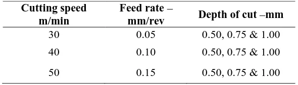
Table 3. Operating parameters
Cutting speed m/min
Feed rate –
mm/rev Depth of cut –mm
30 0.05 0.50, 0.75 & 1.00
40 0.10 0.50, 0.75 & 1.00
50 0.15 0.50, 0.75 & 1.00
3. Results And Discussion
3.1. Surface roughness
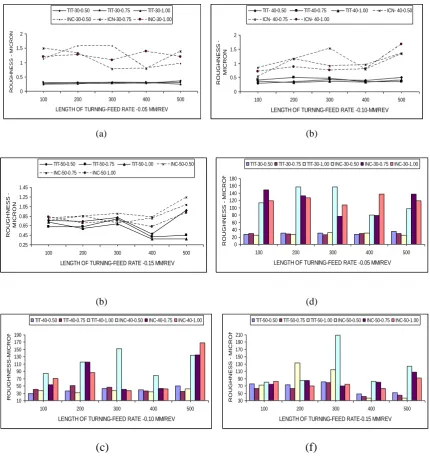
Formation of the machined surface is closely associated with the reaction of the edge of cutting tool and workpiece. Dhar et al. [10] reported that the surface roughness was low with cryogenic treated inserts in comparison with non-treated inserts at all cutting speeds. This has been more or less true for all the work – tool combinations undertaken in this research. Wuyi Chen [11] stated that the surface roughness would be low when the hardness of the material increased. Lateral plastic flow of the work material in front of the cutting edge increased roughness of the machined surfaces. Thakur et al. [12] turned Inconel 718 material by tungsten carbide tool and reported that the roughness value decreased at high cutting speed but increased as the feed rate increased. This was due to increased friction between work material and tool interface which eventually increases the temperature in the cutting zone The surface roughness values are higher when lower feed rate was used, while the roughness values were smaller when higher feed rate was employed in the tests. This is presumably, is due to ploughing action caused by smaller uncut chip thickness [13, 14]. Rougher surface at small feed rate may associate with minimum chip thickness. Figure 2 (a to f) show graphical representation of surface roughness against operating parameters as given in the Table 3. The surface roughness obtained at cutting speed of 30, 40 and 50 m/min with at feed rate is low in turning Titanium than Inconel 718 alloy steel even after 500 mm length turning. Smooth roughness obtained at cutting speed of 50 m/min with feed rate 0.05 mm / rev. at 1 mm depth of cut. This was due to more tool plough effect and plastic deformation produced low surface roughness.
Thakur et al. [12] turned Inconel 718 material by tungsten carbide tool and reported that the roughness value decreased at high cutting speed but increased as the feed rate increased. This was due to increased friction between work material and tool interface which eventually increases the temperature in the cutting zone. The surface roughness values are higher when lower feed rate was used, while the roughness values were smaller when higher feed rate was employed in the tests. This is presumably, is due to ploughing action caused by smaller uncut chip thickness [13, 14]. Rougher surface at small feed rate may associate with minimum chip thickness. Figure 2 (a to f) show graphical representation of surface roughness against operating parameters as given in the table 3. The surface roughness obtained at cutting speed of 30, 40 and 50 m/min with at feed rate is low in turning Titanium than Inconel 718 alloy steel even after 500 mm length turning. Smooth roughness obtained at cutting speed of 50 m/min with feed rate 0.05 mm / rev. at 1 mm depth of cut. This was due to more tool plough effect and plastic deformation produced low surface roughness.
5
(a) (b)
(b) (d)
[image:5.595.80.511.115.575.2](c)
(f)
Figure 2. Graphs showing length of turning vs surface roughness: (a) 30 m/min cutting and feed rate
of -0.50 (b) 40 m/min cutting speed with 0.10 feed rate (c) 50 m/min cutting speed with 0.15 feed rate, (d) DOC of 0.50 mm, (e) DOC of 0.75 mm and (f) DOC of 1.00
3.2. Tool Flank Wear
Flank wear is formed on the flank side of the insert which is due to rubbing action of the insert and machining surface. Figure 3 shows the various tool wear that is likely to occur as per ISO 3685 of 1993 [15]. The tools often fail rapidly due to non-uniform flank wear, chipping, depth of cut notching, and plastic deformation of the cutting edge even at relatively low cutting. Low thermal conductivity (11.4 W/m K), leading to high cutting temperature in cutting and high strength under high temperature are responsible for its generally poor machinability [6]. In addition, the cutting forces generated are also very high around double that found when cutting medium carbon steels [7]. This, in combination with the relatively short chip contact length and high cutting temperature, induces very high stress concentration on the area of tool / work piece interaction and leads to highly plastics deformation in
0 0.5 1 1.5 2
100 200 300 400 500
LENGTH OF TURNING-FEED RATE -0.05 MM/REV
R O U G H N E S S M IC R O N
TIT-30-0.50 TIT-30-0.75 TIT-30-1.00
INC-30-0.50 ICN-30-0.75 INC-30-1.00
0 0.5 1 1.5 2
100 200 300 400 500
LENGTH OF TURNING-FEED RATE -0.10-MM/REV
R O U G H N E S S - M IC R O N
TIT- 40-0.50 TIT-40-0.75 TIT-40-1.00 ICN- 40-0.50
ICN- 40-0.75 ICN- 40-1.00
0.25 0.45 0.65 0.85 1.05 1.25 1.45
100 200 300 400 500
LENGTH OF TURNING-FEED RATE -0.15 MM/REV
R O U G H N E S S - M IC R O N
TIT-50-0.50 TIT-50-0.75 TIT-50-1.00 INC-50-0.50
INC-50-0.75 INC-50-1.00 0 20 40 60 80 100 120 140 160 180
100 200 300 400 500
LENGTH OF TURNING-FEED RATE -0.05 MM/REV
R O U G H N E S S - M IC R O N
TIT-30-0.50 TIT-30-0.75 TIT-30-1.00 INC-30-0.50 INC-30-0.75 INC-30-1.00
10 30 50 70 90 110 130 150 170 190
100 200 300 400 500
LENGTH OF TURNING-FEED RATE -0.10 MM/REV
R O U G H N E S S -M IC R O N
TIT-40-0.50 TIT-40-0.75 TIT-40-1.00 INC-40-0.50 INC-40-0.75 INC-40-1.00
30 50 70 90 110 130 150 170 190 210
100 200 300 400 500
LENGTH OF TURNING-FEED RATE-0.15 MM/REV
R O U G H N E S S - M IC R O N
6
[image:6.595.206.388.195.313.2]cutting edge and work piece material. Manu Dogra et al. [15] found that during the turning of hardened AISI 4340 steel using CBN-TiN coated carbide and PCBN tools, result revealed that tool life of CBN –TiN coated carbide inserts was approximately 18-20 min per cutting edge, whereas PCBN tools produced a tool life of 32 min. Flank wear is primarily attributed to rubbing of the tool along the machined surfaces, causing abrasive diffusive and adhesive wear mechanisms and also high temperature, which affect the tool material properties as well as work piece surface.
Figure 3.
Various tool wear on a single point tool [15]
(a) (b)
(c)
Figure 4. Graph showing length of turning Vs flank wear (a) 30 m/min cutting and feed rate of -0.50
(b) 40 m/min cutting speed with 0.10 feed rate and (c) 50 m/min cutting speed with 0.15 feed rate.
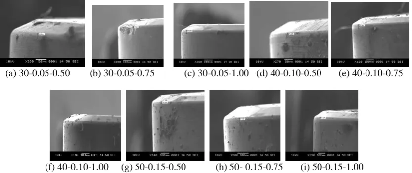
In all the cutting speeds, flank wear was formed more at low feed rate of 0.05 mm/rev. Titanium alloy steel. At 1 mm depth of cut in turning Inconel 718, the flank wear was low than 0.50 and 0.75 mm depth of cut. In this research, it was found that flank wear formation was high in Titanium than Inconel 718 and shows that Titanium alloy is difficult to cut metal. Figure 4 (a to c) show graphical representation of flank wear for all the three parameters. Figure 5 (a to i) shows SEM view on flank wear by titanium alloy and more abrasion occurred than Inconel 718. Figure 6 show SEM view on flank wear by Inconel 718 alloy steel which shows less flank wear.
20 40 60 80 100 120 140 160 180
100 200 300 400 500
LENGTH OF TURNING-FEED RATE-0.05-MM/REV
F L A N K W E A R - M IC R O N
TIT-30-0.50 TIT-30-0.75 TIT-30-1.00 INC-30-0.50
INC-30-0.75 INC-30-1.00 0 20 40 60 80 100 120 140
100 200 300 400 500
LENGTH OF TURNING - FEED RATE -0.10-MM/REV
F L A N K W E A R - M IC R O N
TIT-40-0.50 TIT-40-0.75 TIT-40-1.00 INC-40-0.50
INC-40-0.75 INC-40-1.00 0 20 40 60 80 100 120
100 200 300 400 500
LENGTH OF TURNING-FEED RATE-0.15 MM/REV
F L A N K W E A R - M IC R O N
TIT-50-0.50 TIT-50-0.75 TIT-50-1.00 INC-50-0.50
[image:6.595.82.506.355.626.2]7
(a) 30-0.05-0.50 (b) 30-0.05-0.75 (c) 30-0.05-1.00 (d) 40-0.10-0.50 (e) 40-0.10-0.75
[image:7.595.98.503.112.285.2]
(f) 40-0.10-1.00 (h) 50- 0.15-0.75 (i) 50-0.15-1.00
Figure 5. SEM view on flank wear on Titanium alloy
(a) 30-0.05-0.50 (b) 30-0.05-0.75 (c) 30-0.05-1.00 (d) 40-0.10-0.50 (e) 40-0.10-0.75 (f) 40-0.10-1.00
[image:7.595.87.506.323.506.2]
(g) 50-0.15-0.50 (h) 50- 0.15-0.75 (i) 50-0.15-1.00
Figure 6. SEM view on crater wear while turning Titanium
(a) 30-0.05-0.50 (b) 30-0.05-0.75 (c) 30-0.05-1.00 (d) 40-0.10-0.50 (e) 40-0.10-0.75
(f) 40-0.10-1.00 (g) 50-0.15-0.50 (h) 50- 0.15-0.75 (i) 50-0.15-1.00
[image:7.595.91.508.544.719.2]8
3.3. Crater wear
Crater wear is formed at rake face of the tool. Figure 3 shows the various crater wear formation which is represented by KT. The ISO 3685 of 1993 recommends the criterion of tool life due to crater wear and can be calculated by using the formula as given below:
KT =
0
.
06
0
.
3
f
(1)
where f is the feed rate and KT is the depth of crater.
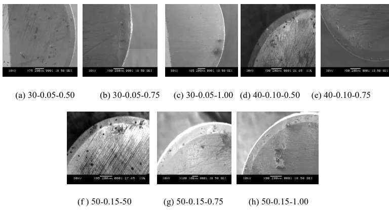
Crater wear is dished out section which develops on the rake face of the tool. The formation of crater wear occur little away from the cutting edges. In fact at low cutting speed, crater wear is usually insignificant compared with flank wear in normal operations. There is no standard available for maximum depth of the crater specification like flank wear. Deeper crater will lead to failure of the cutting edge. When machining using CBN, PCBN inserts and other high strength inserts the formation of wear take longer time. At high cutting speeds crater wear formation would be more severe and depth of crater KT will be deeper. While turning difficult to cut materials crater wear was more due to saw tooth chips. In turning Titanium alloy, the formation of crater wear was low than Inconel 718. The saw tooth chips rougher and deeper crater formed. Figure 6, 7 and 8 show the crater wear formed while turning Titanium and Inconel 718 respectively. More craters formed in turning Titanium than Inconel 718.
(a) 30-0.05-0.50 (b) 30-0.05-0.75 (c) 30-0.05-1.00 (d) 40-0.10-0.50 (e) 40-0.10-0.75
[image:8.595.107.491.369.577.2]
(f ) 50-0.15-50 (g) 50-0.15-0.75 (h) 50-0.15-1.00
Figure 8. SEM view on crater wear on Inconel 718 alloy
4. Conclusions
The following conclusions were arrived in this research. They are:
Surface roughness obtained in turning Titanium alloy was low at cutting speed 50 m/min than 30 and 40 m/min than Inconel 718.
Surface roughness at depth of cut 1 mm is low than 0.50 and 0.75 mm in Titanium alloy than Inconel 718.
Flank wear by Inconel 718 was low than Titanium. Flank wear at 1 mm depth of cut was low than 0.50 and 0.75 mm.
9
Cryogenic treated inserts performed very well by producing smooth surface roughness in Titanium alloy than Inconel 718. On the other hand, flank wear was low in turning Inconel 718 than Titanium alloy.
Acknowledgements
The authors would like to thank International College of Automotive (ICAM) and Ministry of Higher Education Malaysia for their financial support via Fundamental Research Grant Scheme (FRGS) Vot 0751.
References
[1] Ezugwu E O, Wang Z M, and Machado A R 1999 The machinability of nickel-based alloys: a review Journal Mater Process Technol 86 1-16.
[2] Barron R F, 1982 Cryogenic treatment of metals to improve wear resistance Cryogenics22 409-413
[3] Seah K H W, Rahim M, and Yong K H 2003 Performance evaluation of cryogenically treated tungsten carbide cutting inserts Proc. Inst.Mech.Eng. Part B: J Eng Manuf.217 29-43
[4] Arunachalam R, and Mannan M A 2000 Machinability of nickel based high temperature alloys.
Mach. Sci. Technol.4 127–168
[5] Ezugwu E O, Bonney J, and Yamane Y 2003 An overview of the machinability of aeroengine alloys J. Mater. Process. Technol.134 233–253
[6] Watmon T B, and Anthony C I 2010 Coating cutting tools with hard substance lowers friction co-efficient and improves tool life—a review. In: Proceedings of the International Multi-Conference of Engineering and Computer Scientists IMECS (Hong Kong )pp 17–19.
[7] Pawade R S, Suhas S, Joshi S, Brahmankar PK and Rahman M 2007 An investigation of cutting forces and surface damage in high speed turning of Inconel 718 J. Mater. Process. Technol. 139–146
[8] Sharman A R C, Dewes R C and Aspinwall D K 2001 Tool life when high speed ball nose end milling Inconel 718 J. Mater. Process. Technol. 118 9–35
[9] Sadat A B and Reddy M Y 1992 Surface integrity of Inconel-718 nickel-base super alloy using controlled and natural contact length tools. Part I. Lubricated. Exp Mech. 32 282–288
[10]Dhar N R, Paul S and Chattopadhyay A B 2002 Machining of AISI 1045 steel under cryogenic cooling –tool wear, surface roughness and dimensional deviations Journal of Materials Processing Technolog, 123 483-489
[11]Wuyi Chen 2000 Cutting forces and surface finish when machining medium hardness steel using CBN tools International Journal of Machine Tools and Manufacture40 455-466.
[12]Thakur D G, Ramamoorthy B and Vijayaraghavan L 2008 Study on the Machinability characteristics of super alloy Inconel 718 during high speed turning Materials and Design
350-6
[13]Zhou BM, Chen C, Huang Q and An Q, 2009 Study on surface damages caused by turning NiCr20TiAl nickel-based alloy J. Mater. Process. Technol., 209 5802–5809
![Figure 1. High-speed cutting ranges in machining of various materials [1]](https://thumb-us.123doks.com/thumbv2/123dok_us/8765821.896365/2.595.158.434.154.313/figure-high-speed-cutting-ranges-machining-various-materials.webp)

![Figure 3. Various tool wear on a single point tool [15]](https://thumb-us.123doks.com/thumbv2/123dok_us/8765821.896365/6.595.82.506.355.626/figure-various-tool-wear-single-point-tool.webp)