2017 2nd International Conference on Computer, Network Security and Communication Engineering (CNSCE 2017) ISBN: 978-1-60595-439-4
Research of Robot Tutorial Software Systems
Xin-yang WANG
1and Jian ZHANG
21
Guangdong Vocational Technology Institute, China
2Foshan Southern Institute of Data Science and Technology, China
Keywords: Two dimension of freedom robot, Dynamic linked library, Man-machine interface, Tutorial function, Hand drawing
Abstracts. An independent server program of drawing panel based on the original software system of SCARA 2-DOF Googol robot is developed in this paper through utilizing the common module mode of Windows platform—DLL (Dynamic Linked Library). Not only complex mathematic graph but also arbitrary hand drawing with mouse can be realized conveniently. This software operating system has good expansibility and widespread applicability. Besides complex mathematic 2-dimension graph, arbitrary hand drawing with mouse can be realized conveniently comparing with the original simple tutorial function.
Introduction
In 1960, American Unimation Corporation developed the first robot prototype according to Devol’s controllable mechanical arm idea and manufactured Unimate robots. Meanwhile, AMF Corporation designed and manufactured another programmable robot Versatran in a form of cylindrical coordinate. As the first most famous industrial robots applied till now, the above two robots successfully replace workers for transfer, welding, painting, etc. in the automobile production line through “tutorial reproduction”, and present good economic benefit, reliability and flexibility in operation. In 80s of the 20th century, development and wide application of computer technology and power electronics greatly widely and deeply extended the robot technology. Currently, the widely applied robots include the industrial mechanical arm manufactured by American Adept Corporation, Motoman series industrial mechanical arm manufactured by Japanese YASKAWA, industrial mechanical arm manufactured by Swiss ABB Corporation, etc. For high system safety & reliability and convenient use, closed architecture, dedicated control software and hardware are adopted for these industrial robot systems mainly oriented to industrial application. Joint structure design similar to Adept SCARA robot is adopted for GRB200 robot manufactured by Googol Technology (Shenzhen) Ltd., and simple point-to-point transfer can be finished with such device and supporting software, but it is fairly difficult to realize complex tutorial task due to software system limitation, so it is necessary to extend tutorial function maximally without changing the original system. Based on original software system of 2-DOF robot, utilizing the standard Windows operating system environment, an individually and easily extendable man-machine interface and convenience operations are provided by means of dynamic-linked-library. Not only complex mathematic 2-dimension graph but also arbitrary hand drawing with mouse can be realized conveniently comparing with the original simple tutorial function.
Operating Principle of Mechanical Arm
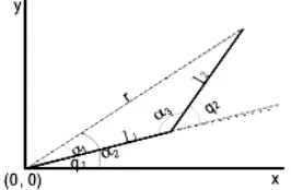
For the projection of 2-DOF mechanical arm into plane coordinates as shown in Figure 1, the solid line represents the mechanical arms—mechanical arm 1 started from the origin and mechanical arm 2 connected thereto, wherein the drawing pen installed at the top end of mechanical arm 2 is used for drawing. The combined motion of two mechanical arms must be analyzed and controlled for correct locus motion. Limited to plane motion, the plane geometry method can be directly used for finding the joint angle for the mechanical arms.
Figure 1. Projection of 2-DOF Mechanical Arm in Plane Coordinates.
The kinematic positive solution of the endpoint coordinate of mechanical arm 2 can be obtained according to Figure 1:
+ + = + + = ) sin( sin ) cos( cos 2 1 2 1 1 2 1 2 1 1 q q l q l y q q l q l x (1)
Where l1 and l2 are respectively the connecting rod lengths of robot joints 1 and 2, mm; q1 and q2 are radians. The kinematic inverse solution is as follows:
= = = − + = − = = − + + = ) , ( 2 tan ) cos , (sin 2 tan cos 2 3 sin sin cos 1 sin cos 2 2 1 1 1 1 1 2 2 2 1 2 2 1 3 2 3 3 2 1 2 2 2 2 1 2 2 2 x y a a rl l l r r l l l r l l y x r α α α α α α α α α α (2)
Accordingly, the kinematic inverse solution expression is obtained as follows:
− − − = − = 1 1 1 1 1 2 1 2 1 )) cos ( ), sin (( 2
tan y l q x l q q a
q
q α α
(3)
Whereαtan2(y, x) is the mathematical function for calcualting the arc tangent of y/x (unit:
radian), with value range of (-π/2,π/2).
The original system is only provided with several kinds of simple drawing demo software. We expect to add other curvilinear equations and functions in the original man-machine interface to make users select the added curvilinear equations and freely draw in the effective range even with mouse so as to finish the designated tasks through such mechanical arm. Theoretically, for a given group of rectangular coordinate data, the system obtains interpolation position sequence p[n]=(x[n],
y[n]) and interpolation speed sequence p[n]=(x[n],y[n])in the rectangular coordinate space through locus interpolation, and then formula (2) is adopted for the kinematic inverse solution of each pairs of interpolation position and speed to obtain target joint position q[n]=(q1[n], q2[n]) and
speed q[n]=(q1[n],q2[n])of the robot. Finally, joint position and joint speed are input as the
current q1 and q2, formula (1) is adopted to obtain the rectangular coordiante data for current position through the kinematic positive solution.
Graphical Tutorial System Design
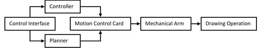
[image:3.612.86.523.212.294.2]Hierarchical structure is adopted for the whole system, as shown in Figure 2. Universal PC is taken as the master controller and the main control program of the robot runs thereon to provide user interface, finish task planning, kinematic positive/inverse solution, coordinate transformation, etc., and issue robot joint tasks (speed and acceleration for the motion to a certain position) to the motion controller. As a subordinate controller, DSP high-performance motion controller employs certain control strategy to control joint motor motion.
Figure 2. Schematic Diagram of Graphical Tutorial System Structure.
PC master controller communicates with DSP subordinate motion controller through PC bus, wherein the motion controller provides the drive program function library in the operating system and the master controller calls the function library to issue tasks and detect the command execution state. The control signal of DSP controller is sent to various joint motor drivers in the control cabinet for driving the robot joint motor after operational amplification. Hierarchical independence is realized in the motion control system through such hierarchical structure design. The controlled objects of the master controller and DSP motion controller are respectively robot joint and specific motor control axis between which the corresponding relationship is determined by robot model, thus realizing motion controller universalization.
It is not easy for general mechanical arms able to realize point-to-point motion to finish the motion among multiple points. Similarly, 2-DOF mechanical arm must be moved to corresponding coordinate positions by the sequence contrary to the practical operations, and these coordinates should be recorded to realize point-to-point motion through playback. In tutorial process, for moving the mechanical arms to accurate coordinate points, mechanical arms 1 and 2 must be cooperatively moved, usually for several times. In case of complex operation tasks (dozens of tutorial points or with the requirements for the curvilinear motion of the mechanical arm), the tutorial process will become very long and tedious. For tutorial process simplification, an independent drawing panel is added to the original control panel to make the mechanical arms not only conveniently finish common tutorial tasks but also have the ability for complex mathematic arbitrary hand drawing, thus becoming more competent for more complex operation tasks.
Software Implementation of Arbitrary Graphical Tutorial System
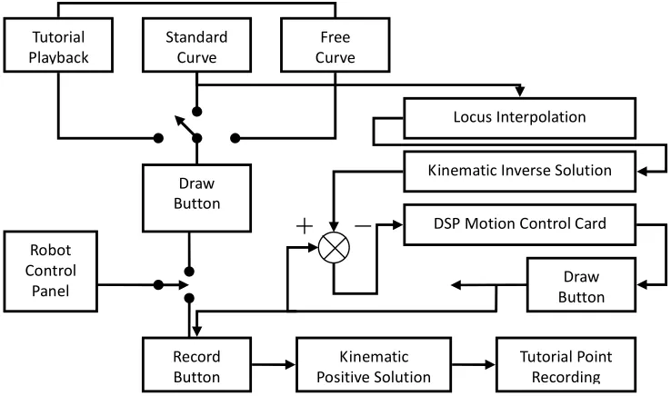
Software principle diagram of the graphical tutorial system is as shown in Figure 3. Through function addition, the robot has three drawing operation modes: tutorial playback, standard curve drawing and mouse drawing. In any above mode, a group of rectangular coordinate data is finally given after corresponding operation. Specifically, the interpolation position sequence and the speed sequence are obtained in the rectangular coordinate space through the locus interpolation of this group of data, then target joint position and speed of the robot are obtained through the kinematic inverse solution, and finally joint position and speed are input as the reference signals into the motion controller to drive the motion platform. Before tutorial playback, the joint position of current mechanical arm must be obtained through Record button in order to obtain the tutorial points through the kinematic positive solution.
Control Interface
Controller
Planner
Figure 3. Software Principle Diagram of Graphical Tutorial System
For convenient updating and function extension in future, the designed drawing panel with new functions is independent of the original control system. Utilizing common module idear of Windows system, this drawing panel is designed in Visual C++ programming environment as MFC based DLL (Dynamic Linked Library) service program. If such function is needed during original control system operation, this service program can be dynamically loaded and automatically unloaded after drawing operation. DLL service program mainly includes a property sheet (CPropertySheet) CPaneSheet with two property pages—(CPropertyPage) CDrawPane and CNormalPane, wherein the former one is the dialog box for drawing free curves and the latter one is the dialog box for drawing standard curves. As extension classes, classes CPaneSheet, CDrawPane and CNormalPane must be manually modified in the generated DLL project, and AFX-EXT-CLASS should be added during class declaration. Head files of pane.h (head files of classes CDrawPane and CNormalPane) and panesheet.h must be copied under the directory of the project files of the original control system.
Firstly, after the establishment of MFC based extended DLL project, the dialog box resource template for drawing free curves is added to the project and the corresponding CpropertyPage based class is generated to be conveniently embedded as the property page into the property sheet in future for processing. If not starting drawing in the free curve drawing panel, the user can click the mouse and move it for drawing operation, and clear the existing graph; during drawing operation, the user can click the mouse to finish the drawing operation and it is forbidden to move the graph with mouse. If drawing is allowed at present, the user can move the mouse in the free curve drawing panel to save the product of the scale factor and the difference between current mouse coordinate and drawing start point (the coordinate point of the first mouse click point is regarded as the start point, namely zero point) in arrays posInfoX and posInfoY, and meanwhile display the title bars thereof in the property sheets for user’s convenient observation, wherein posInfoX and posInfoY are dynamically adjusted according to the number of the locus points currently obtained. When the point number is over the maximum value (MAXLEN, set by the developer) allowed by the system, current drawing operation will be forced to be ended. Therefore, OnLButtonDown() and OnMouseMove() are added to realize above function. The free curve drawing panel is a property page of the whole drawing panel property sheet, so it is necessary to consider the cases of switching this page to other pages or reactivating this page. Specifically, OnKillActive() is added to release memory space and clear some flag bits when switching the free curve drawing panel to another property page; OnSetActive() is added to clear the drawn graph when reactivating this page, display “Draw Free Curve” in the title bar of the property sheet and prepare for drawing new free curves; OnInitDialog() is added to display “Draw Free Curve” in the title bar of the property sheet,
Robot Control
Panel
Record Button
Tutorial Point Recording Kinematic
Positive Solution Draw
Button Tutorial
Playback
Standard Curve
Free Curve
Locus Interpolation
Kinematic Inverse Solution
DSP Motion Control Card
dynamically allocate the program running period for saving locus point arrays, set background color, etc. at the first time of opening the free curve drawing panel; OnSetCursor() is added for user-friendly interface, and the system can call this function during idle time to change mouse shape according to current operation state: the mouse is presented as a “cross” shape during idle operation but as an “upwards inclined arrow” during drawing operation.
Secondly, the dialog box resource template for drawing standard curves is added for the project and the corresponding CpropertyPage based class is generated to be conveniently embedded as the property page together with the free curve drawing panel class into the drawing panel property sheet. The standard curve panel is provided with a curve type combo box and a graph preview window, and the user can freely select curve types in the combo box, and the panel can call corresponding curve function according to user’s current choice to obtain a series of discrete points and finally display the graph corresponding to current curve type. Therefore, OnSelchangeComboNormalSel() and OnUpdatePrev() and the following six drawing functions are added: OnDrawCircle(), OnDrawFourrose(), OnDrawHeart(), OnDrawSquare(), OnDrawEllipse() and OnDrawTriangle(). The above drawing functions can obtain the discrete points according to the corresponding curvilinear equation and save them in the standard arrays; OnUpdatePrev() function is used to update the graph in the preview window according to the data in current locus array. OnInitDiaLog(), OnKillActive() and OnSetActive() of this standard curve drawing panel are similar with those of the free curve drawing panel.
Then, the drawing panel property sheet class is established, and the property pages of above free curve drawing panel and standard curve drawing panel are embedded into this property sheet. “Apply” button on the drawing panel is selected to activate OnApply() to send corresponding drawing operation command to the main window of the original control system according to current active page. For obtaining the main window handle of the client program to realize the communication between DLL service program and the client program of the original control system, GetClientWnd() member function is added and the client program can call this function during running to obtain the main window of the original control system.
Finally, the project files of the original control system are slightly modified. First, a new menu item is added in the project, the message processing function is also added, and the drawing panel service program is loaded in this function. Second, OnDrawPaneApplied() and OnNormalPaneApplied() for processing the drawing commands are added respectively for the free curve drawing panel and the standard curve drawing panel, and they can start the mechanical arm to draw in the control platform according to current curve locus. Third, the head files (Pane.h and PaneSheet.h) of the extended class, library file (*.LIB) and DLL files (*.DLL) under the directory of the drawing panel service project are copied to the directory of the control system service project. Fourth, the project is recompiled and reconnected. In future, under the condition of not changing the head files—Pane.h and PaneSheet.h of the extended class, it is only necessary to modify the drawing panel service project and then update *.LIB and *.DLL files under the directory of the original control system project to update the drawing panel.
Conclusion
An independent server program of drawing panel based on the original software system of SCARA 2-DOF Googol robot is developed in this paper through utilizing the common module mode of Windows platform—DLL (Dynamic Linked Library). Not only complex mathematic graph but also arbitrary hand drawing with mouse can be realized conveniently. Furthermore, this control system has good expansibility and widespread applicability, network and vision function can be further added with the same idea.
References
[2] Du Haofan, Cong Shuang, Li Zexiang, et al. A 4-DOF Robot System for Handling and Assembling Operations [J]. Manufacturing Automation, 2013, 25(7): 33-37.
[3] Googol Technology (Shenzhen) Ltd., User Manual for Mechanical Arm [Z]. 2013.