2018 International Conference on Modeling, Simulation and Analysis (ICMSA 2018) ISBN: 978-1-60595-544-5
Analysis of Stray Light Suppression for Space-based
Space Objects Detection System
Kun-peng WANG
1,*, Wen-tang WU
1, Xing ZHONG
2, Jian-yu HUANG
1and Dong-ya WANG
11Beijing Institute of Tracking and Telecommunications Technology, Beijing, China
2Chang Guang Satellite Technology CO., Ltd., Changchun, China
*Corresponding author
Keywords: Space object, Space-based detection, Stray light suppression, Point source Transmittance.
Abstract. Stray light can directly influence the imaging quality and detection ability of space based detection system, and the stray light suppression of earth radiation is a key question needed to be considered by on-orbit detection system. First the basic principle and the mathematical model of stray light were analyzed here, then by using simulation analysis the requirements of stray light suppression under different imaging situations were obtained, this could be supportable for the design of space-based detection system.
Introduction
Compared with the ground-based objects detection system, the space-based objects detection system is becoming the main means and development direction of space target detection, which has all day long surveillance, all-weather surveillance, full airspace surveillance, have maneuverability,
long distance and other advantages1,2. However, the space-based space objects detection system is
susceptible to stray light caused by the sun, earth and moon, and the target SNR decreases, the image is blurred and the image contrast is reduced, which seriously affects the optical System
imaging performance and detection capability3. The space-based space objects detection system
sometimes causes the target to be buried in the stray light background, which leads to lower target detection rate, serious omission and false detection, and the whole optical system will invalid. Therefore, stray light suppression is a problem which must be considered in the design of the space-based space objects detection system, and also the key factor to enhance the system capability
of the space - based space objects detection system4.
The stray light that affects space-based space objects detection system mainly includes solar stray
light, moon stray light, ground gas stray light and stray light inside optical system5. Most
space-based space objects detection systems work back to the sun and can circumvent the effects of solar stray light by turning off and setting the angle of view. The orbital period satellite platform is much smaller than the period of revolution of the moon, the moon are small stray light affect the probability of detection system, the optical system internal stray light can be through the system design optimization to solve. Therefore, space-based space objects detection system mainly
considers the problem of the stray light suppression of earth radiation6. In this paper, the generation
mechanism and theoretical model of the stray light suppression of earth radiation are analyzed, and the ability of different imaging conditions to eliminate stray light is given by simulation.
Mechanism Analysis
Figure 1. Schematic diagram of the stray light suppression of earth radiation source.
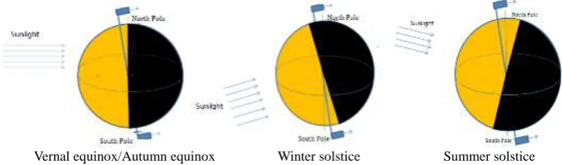
Due to the changes of the camera in the space-based detection system, the light zone, and the radiation exchange coefficient in the shadow interval varies with the seasons and the position of the orbital, so the variation of the ground gas and scattered light varies with the seasons and the position of the orbital. The sun synchronous orbit is one of the most commonly used orbits of the space-based detection systems. Figure 2 shows geometric relationship between the sun, the earth and the satellite at different seasons when the solar synchronous orbit space-based detection system is in different seasons.
Vernal equinox/Autumn equinox Winter solstice Summer solstice
Figure 2. Geometric relationship between satellite and earth in different seasons.
As can be seen from the figure, the sun synchronous orbit space-based detection system, from the spring to the summer solstice, from the autumnal equinox to the winter solstice, the track surface and the twilight circle angle is larger, reflecting sunlight into the gas detection camera surface area increases gradually, that is, under the star point trajectory and twilight circle and can reflect the sun to the camera's surface area gradually increased, then the impact of the air on the camera is also growing. In the course of satellite operation, when the satellite is located above the pole, it can reflect the sunlight and enter the ground surface of the camera with the largest surface area. To ensure that the camera can work effectively at any time of the year, the stray light received from the load above the pole during the summer solstice and winter solstice is effectively suppressed.
Modeling
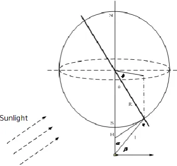
[image:2.595.92.498.369.488.2]Figure 3. The position relationship between sunlight, satellite and earth.
The sun enters a certain position on the surface of the earth, illuminating a tiny area of ( , , )
S R
. Where ( , , )R is the polar coordinates of the tiny region, and R is the radius of the
earth. As a surface light source, the radiation intensity of small area △S is L. The formula for L is:
cos( )
sun sun E
L
(1)
Where Esum is the illuminance produced by the sunlight in the visible light band on the surface of
the earth, is the reflectivity of the earth, and sum is the angle between the direction of the incident
light of the sun and the normal direction of S R( , , ) . The surface light source S R( , , ) of the
atmospheric surface reaches the camera, and the angle between the light and the camera's axis is , so
the reception surface of the camera perpendicular to the gas light is as follows:
2
cos ( ) L s E
l
(2)
Where l is the distance between the tiny surface light source S R( , , ) and the camera on the
surface of the earth, s is the area of the surface light source, and
is the angle between the surface light source and the camera connection direction and the surface light source. According tothe camera in Fig. 3, the triangular relationship between the surface S R( , , )
and the center ofthe earth, we can calculate:
2 2
2 2 2
sin cos cos sin
cos arctan
cos ( )
R sin [Rcos ]
sun E R R H E S R H (3)
The upper equation is the irradiance of the face S of the Earth's surface polar coordinate
( , , )R
at the camera's plane perpendicular to the ground.The index of optical system suppression of stray light is often used as point source transmission ratio PST, which is defined as:
( ) ( ) b E PST E
(4)
Where Eb( ) is the irradiance generated by the stray light source in the direction from the
off-axis angle in the camera system detector, and E( )
is the irradiance on the input apertureThe stray light suppression of earth radiation is incident on a range of angles within the space camera system. Assuming that the airborne stray light produces an illuminance on the image plane of the camera as Eb, then Eb is
* ( )
b
E PST E
(5)
Where Eb is the sum of the illuminance caused by the stray light suppression of earth radiation
incident on the image plane from each direction.
The system on the off-axis angle of the PST value can be determined according to the structure of stray light suppression by the optical mechanical system. According to the formula above, the irradiance of the micro surface of the atmospheric surface can be determined. Meanwhile, the illuminance of the ground clutter can be calculated on the image plane of the space camera.
PST Capability Requirements Analysis
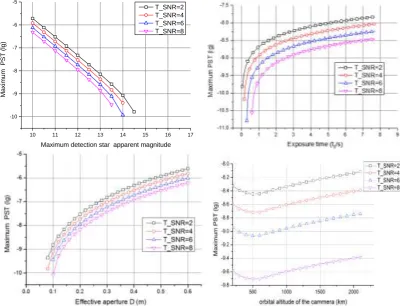
[image:4.595.97.498.352.658.2]An integrated PST index of optical system suppression of stray light is affected by exposure time, target pupil irradiance, optical system effective aperture, transmittance, dark current noise, readout noise, detector SNR threshold, solar illumination angle, camera orbit height and other parameters of the integrated impact. According to the simulation method, the analysis results of PST requirements under the conditions of different target detection star, detector SNR threshold, optical system effective aperture, exposure time and so on are shown in Figure 4.
Figure 4. The PST curves under different conditions.
For different target magnitude, when SNR threshold, with the magnitude of increase, the higher requirement for PST and, when the target magnitude beyond a certain range, the system does not play the role of suppressing stray light. When the target detection magnitude is certain, PST is negatively correlated with SNR threshold value, and the higher the SNR threshold is, the higher the requirement of the system's dissipation astigmatism.
For different exposure time, exposure time has great influence on the detection ability of optical system. When the threshold of SNR is constant, the requirement of eliminating stray light is getting lower with the increase of exposure time.
10 11 12 13 14 15 16 17 -10
-9 -8 -7 -6 -5
Ma
ximum
PST (
lg)
For the different pupil size, the larger the entrance pupil size of the optical system, the stronger the system's ability to collect light, the stronger the detection capability of the system, but the increase in pupil increases the quality and volume of the system, system will lead to the probe saturated at the same time, cause the loss of image contrast. When the system aperture is very small, even if the background noise is 0, the SNR threshold can’t be reached, that is, stray light is difficult to play a role, and with the increase of aperture, the ability to eliminate stray light of the system is rapidly reduced.
For different orbital altitude, the amount of ground stray light is related to the number of earth surface elements, the distance from the surface to the camera, and the imaging load at different orbital heights due to the influence of the stray light suppression of earth radiation. For the same SNR threshold, the change of the orbital height of the camera in the range of 200km ~ 2200km has little effect on the requirement of eliminating the astigmatic capacity, and the variation range of PST is not more than 0.5.
Summary
This paper discusses the effect of space-based detection system susceptible to the stray light of earth radiation. The geometrical model of the effect of stray light is established based on the analysis of its mechanism. The relationship between the stray light of earth radiation index PST and the detection star, exposure time, entrance pupil size and orbital height is simulated and analyzed. The research of this paper is of great significance to the design of space-based detection system. On the basis of the above, the object verification experiment will be carried out by using a prototype of an optical mechanical system, and the specific requirements of stray light suppression in space-based space target detection system will be given by simulation analysis.
References
[1] Y. P. Zhou et al., Study of photoelectric detecting and identifying of space target, Opt. Tech. 27
(2006) 26-33.
[2] G. M. Zhang et al., Model and application of image plane illumination for the space-based
infrared detecting of boost-phasem issile, J. Infrared Millim.Waves. 26 (2007) 425-428.
[3] Q. Hung, Analysis of stray light in space optical system, Infrared. 27 (2006) 26-33.
[4] X. G. Xiao et al., Influence of earth radiation on photoelectric detection system based on space,
Acta Photonica Sinica. 2 (2009) 375-381.
[5] J. J. Zhao et al., Clutter suppression based on adaptive subspace reconstruction, J. Infrared
Millim.Waves. 31 (2012) 47-51.
[6] J. X. Niu et al., Analysis and calculation of space-based infrared detecting system, Acta Optca