2017 2nd International Conference on Computer Science and Technology (CST 2017) ISBN: 978-1-60595-461-5
The Design and Development of Interpretation
and Execution Program for EDDL
Bang-teng LI
1, Yi-ding YUAN
1, Ze DONG
1,a*and Ping MA
21Hebei Engineering Research Center of Simulation & Optimized Control for Power
Generation (North China Electric Power University), Baoding, China
2North China Electric Power University, Hebei
*Corresponding author
Keywords: EDD, EDDL, Micro compiler, Configuration.
Abstract. This paper describes the EDD (Electronic Device Description) and EDDL (Electronic Device Description Language) technology, as well as the development process and the final implementation of the EDDL. The system is developed independently from the preprocessor of EEDL to the final implementation of whole program. This way makes our work more difficult, while makes our system and program more flexible. At the same time, we propose a new means to realize the parsing of METHOD by embedding the micro compiler, instead of by traditional virtual machine assembly language to interpreter. It can also realize the dynamic analysis of METHOD. The experimental results show that the system can generate an operable interface for end users by parsing the DD file to realize the configuration function of the device.
Introduction
In a typical modern industrial control system, there are thousands of devices from different manufacturers, which have different specifications and performance. Those devices need to be configured by different software or manual device, so that an instrument engineer needs to be familiar with many different tools. It not only brings great difficulties to the instrument engineers, but also increases a lot of costs. Therefore, it is necessary to propose a solution to uniformly monitor and configure the field device in the automatic control system, i.e. “device integration”. In recent years, the device integration technology is mainly implemented by the two solutions of EDDL and FDT (Field Device Tool) [1-3]. This paper focuses on the concept of EDDL and its technical realization.
EDD and EDDL Technology
Concept of EDD and EDDL Technology
Device-related EDD and EDDL are designed for industrial automation applications, including conventional digital and analog I/O modules, motion controllers, man-machine interfaces, sensors, closed-loop controllers, encoders, etc [6]. EDDL is a descriptive language based on structured text that describes the electronic (instrument) device. It provides a complete set of basic structural elements to handle simple or complex modular equipment [7]. EDD technology consists of two parts: EDD file and EDD interpreter. EDD file is a text file that is written for the device according to EDDL rules, which contains all the device parameters of the automation system components. EDD interpreter is used to parse the EDD file. EDD technology integrates 3 kinds of mainstream fieldbus technology together, so it is possible for us to the configuration in the same configuration tool software [8-10].
EDD Working Principle
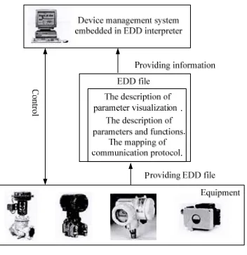
[image:2.612.219.395.307.489.2]The working principle of EDD technology is shown in Figure 1 [11].
Figure 1. Figure headings.
The device manufacturer or the automatic control system manufacturer follows the EDDL specification to compile the appropriate EDD for the device, which contains sufficient information about the device, such as manufacturer, device type, version, etc. The EDD interpreter first obtains the device parameter information and necessary communication protocol information by reading and parsing the EDD file from the field device or directly from the device management system. Then the device management system processes the results of the EDD interpreter. Finally, the system generates a friendly user interface that is consistent with the description of the EDD file, and the engineers can directly configure the device.
Parsing of EDDL File
EDDL Syntax. EDDL consists of three parts: the device information, the basic structural elements and the common attributes. Device information includes
DD_REVISION, DEVICE_REVISION, DEVICE_TYPE, EDD_PROFILE,
information. EDDL basic structure elements include AXIS, BLOCK, CHART, COLLECTION, CONNECTION, DOMAIN, EDIT_DISPLAY, FILE, GREAPH, GRID, IMAGE, IMPORT, LIKE, LIST, MENU, METHOD, PROGRAM, RECORD,
REFERENCE_ARRAY, SOURCE, VARIABLE, VARIABLE_LIST and
WAVEFORM. Each element has a corresponding function. The four most common elements are VARIABLE, MENU, METHOD and COMMAND. This paper focuses on the four elements as an example to analyze their structure.
(1) VARIABLE
VARIABLE describes the parameters contained in the device or EDD application. The lexical structure of it is as follows: VARIABLE identifier, [CLASS, LABEL,
TYPE, HELP, CONSTANT_UNIT, PRE_EDIT_ACTIONS,
POST_EDIT_ACTIONS, PRE_READ_ACTIONS, POST_READ_ACTIONS,
PRE_WRITE_ACTIONS, POST_WRITE_ACTIONS, READ_TIMEOUT,
WRITE_TIMEOUT, RESPONSE_CODE, HANGLING, VALIDITY]. We take the variable CommError_00A0_00A0 as an example.
VARIABLE CommError_00A0_00A0 {
LABEL [comm_err_dp_read_error];
HELP [comm_err_dp_read_error_help];
CLASS LOCAL;
TYPE ENUMERATED (1)
{
DEFAULT_VALUE 1;
{0, [ignore] },
{1, [check] }
} }
As shown above, for the CommError_00A0_00A0 variable, LABEL indicates the name of the element, and HELP specifies the text that provides the structure description. It can be seen that the value corresponding to LABEL and HELP is in the form of "[xxx]". In this case, we need to search the corresponding DCT file of the DD to get the final information. The current CLASS value is LOCAL, which specifies that the VARIABLE is used locally by the EDD application, and the local VARIABLE is not stored in the device, but they can be sent to the device. And TYPE specifies the format of the VARIABLE value. The data type ENUMERATED indicates that VARIABLE is an unsigned integer. It is common to say that the interface of the variable interface is a combo box, where the string "[ignore]" and "[check]" (both need to find the dct file to get the final display) is the contents of the combo box and the value of VARIABLE corresponding to the index of the combo box.
(2) MENU
The MENU organizes variables, methods and other items specified in the EDDL into a hierarchical structure. It describes how data is presented to the user by the EDD application, and the application will display MENU ITEMS in organized and consistent
form. Its lexical structure is: MENU identifier
[ITEM,LABEL,ACCESS,POST_EDIT_ACTIONS,POST_READ_ACTIONS,POST_ WRITE_ACTIONS,PRE_EDIT_ACTIONS,PRE_READ_ACTIONS,PRE_WRITE_ ACTIONS,STYLE,VALIDITY].
{
LABEL [menu_dialog_simulation];
STYLE PAGE;
ITEMS {
func1_simulate_enabled, func1_simulate_value, func1_simulate_status,
phys_hw_simulation_protection(READ_ONLY),
method_set
} }
As shown above, for the menu of Page_simulation, the LABEL property is similar to LABEL in VARIABLE. The STYLE property specifies the display format for the MENU. The current STYLE value is PAGE [12], so it usually presents a dialog box, and all of the ITEMS in this variable will be arranged in a certain order in this interface. The ITEM property specifies the elements that are presented to the user and the qualifications for each element. Those qualifiers constrain the format of the item, such as phys_hw_simulation_protection followed by READ_ONLY indicates that the variable in the current interface is read-only.
(3) METHOD and COMMAND
VARIABLE, MENU element mainly specifies the form of the interface. METHOD and COMMAND element specifies the device interaction information. METHOD is used to define the subroutines that are executed in the EDD application, which describes the interaction between the EDD application and the field device and the conversion algorithm between the EDD variables. COMMAND is a structure that supports the mapping of EDD communication elements to the selected communication system. It maps the device parameters contained in the EDD application to the supported fieldbus communication devices via SLOT and INDEX. Thus, the user can interact with the device by using the specified SLOT and INDEX, without knowing the physical address of the device.
Design and Development of EDDL Interpreter and Execution
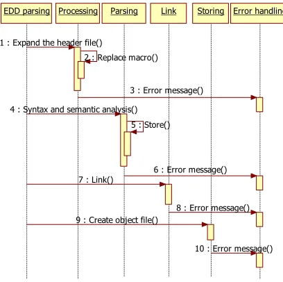
EDD parsing Processing Parsing Link Storing Error handling
1 : Expand the header file()
2 : Replace macro()
3 : Error message()
4 : Syntax and semantic analysis() 5 : Store()
6 : Error message() 7 : Link()
8 : Error message() 9 : Create object file()
[image:5.612.202.406.73.276.2]10 : Error message()
Figure 2: the implementation of EDDL interpreter.
The technical difficulty of the whole process is the parsing of conditional expression and METHOD.
(1) Conditional expression [6]
The conditional expression is used to declare a replacement value or to compute a property value for a primitive element, and the value of the expression is evaluated during execution. There are three main forms of conditional expression.
1. IF expression
The IF condition is used to specify an attribute that has two selectable definitions. The expression specified in the IF condition is evaluated, if the result is nonzero, the attribute is specified by the part THEN; otherwise, the attribute is specified by the part ELSE.
2. SELECT expression
The SELECT condition is used to specify attributes that have multiple selection definitions. The result of SELECT expression is compared to each integer n of CASE. If a matching value is found, the corresponding SELECT condition is valid. If no matching integer n is found, the subsequent DEFAULT condition is used.
3. Basic expression
The expression of the basic expression in the grammar is as follows: expr_specifier
= expr ';'
= 'IF' '(' expr ')' '{' expr_specifier '}' = 'IF' '(' expr ')' '{' expr_specifier '}' 'ELSE' '{' expr_specifier '}'
= 'SELECT' '(' expr ')' '{' expr_selection_list '}' expr_selection_list
= expr_selection
= expr_selection_listexpr_selection expr_selection
It can be seen that the conditional expression contains three forms, and they can also be nested with each other. At the same time, the value of the conditional expression can only be obtained during execution, which makes the whole parsing process very difficult. To this end, we introduced the CCondtionExp class, which contains three-member variables, namely m_pIfStruct, m_pSelectStruct and m_pExpression, to store the conditional expression of the three cases. The executor computes three expressions by calling the function of CCondtionExp class to get the corresponding value for the expression.
(2) METHOD parsing
METHOD contains DEFINITION, LABEL, ACCESS, CLASS, HELP, VALIDTY attributes, and the main difficulty lies in the parsing of DEFINITION. DEFINITION, which is based on the programming language (such as ANSI C), specifies the action to be performed. The compiler is required not only to support the parsing of EDDL, but also to support the parsing of the ANSI C language, which undoubtedly increases a lot of difficulty. Thus, the mini compiler that supports the ANSIC language is embedded in the system to complete the DEFINITION resolution. When parsing DEFINITION, the parser first copies the contents of DEFINITION. And then, in the implementation process, the DEFINITION parsing is done by the embedded micro compiler.
It is very different from the traditional implementation of METHOD. The traditional solution is to rely on the virtual machine assembly language interpreter to parse the statement defined in METHOD one by one, which requires an assembly language conversion process. In this paper, we propose a scheme of embedded micro compiler. It requires only a simple preprocessing of the statement defined by METHOD to implement the interpretation of METHOD. This greatly reduces the difficulty of implementing METHOD, shortening the entire development cycle.
Implementation of EDDL Interpretation and Execution Program
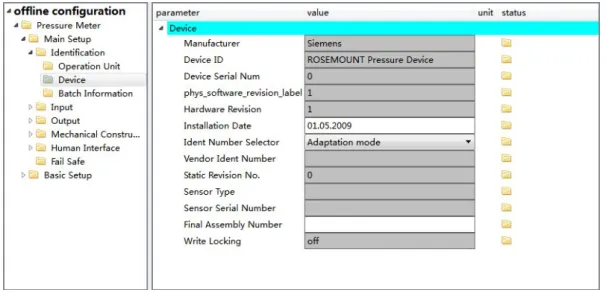
[image:6.612.160.463.519.666.2]According to the above methods and techniques, the electronic device description language interpretation and execution procedures have been developed. As shown in Figure 3, the program is called by the device management system to parse the Rosemount 3051 pressure transmitter DD file, and ultimately generate an operational interface for the end user.
Figure 3: Rosemount 3051 configuration interface.
the system will download all offline parameters from the device. And when the user clicks the download menu, the data that has been modified by the user will be written to the device. In the online parameter interface, the system will periodically update the current device data without any user operation.
Conclusion
In this paper, the development and design process of electronic device description language interpretation and execution program are introduced in detail, and the feasibility of the program is tested. The test results are consistent with expectations that the system can generate an operator interface for the user by parsing the DD file to implement the configuration function of the device.
References
[1] D.Y. Hui. Standardization and measurement of instrumentation. 4(2007):14-18, 2007.
[2] R. Hua, The basic concept of EDDL history and application, China Instruments and meters. 2009(8): 61-63, 2009.
[3] R. Hua, Overview of EDDL technology, China Instruments and meters. 2009(9): 61-63, 2009.
[4] X.Y. Shi, H.D. Gao, X.B. Li, B.H. Zao, EDDL-based design and implementation of filedbus device management system, Thermal power generation. 46(1):121-123, 2017.
[5] F.Y. Zou, R.F. Yang, Design and Application of Smart Device Management System, Automation & Instrumentation. 2013(10):5-10,2013.
[6] GB/T 21099.2-2007, Function blocks for process control Part2: Specification of FB concept and electronic device description language.
[7] W.H. Bao, H. Zhang, D.Q Xu, Research on fieldbus device description technology, East China Electric Power. 34(6):4-8, 2006.
[8] W.H. Bao, M. Lu, Research and implementation of EDDL and FDT technology, Standardization and measurement of instrumentation.2010(1): 42-45,2010.
[9] G.P. Zhou, J. Li, H, Wang. The research and realization of EDDL and FDT Technology, Control Engineering of China. 20(3):526-528, 2013.
[10]G. Michael, Compatibility and Interoperability in Field Device Integration a view on EDDL, FDT and FDI. SICE Annual Conference 2015. 2015, 1156-1161.