A Novel Approach for Turbo Decoding In ISI Channel
Sanjay Kumar Soni
Department of Electrical & Electronics G. B. Pant Engg. College
Pauri (Garhwal) India
Puspraj Singh Chauhan
Department of Electronocs & Telecommunication Engg.
C.O.E.R. Roorkee (India)
K. Vasudevan
Department Of Electrical Engg.
IIT Kanpur (India)
ABSTRACT
Turbo codes are family of forward error correcting codes, whose performance is near Shannon limit. Turbo decoding is based on the maximum a-posterior algorithm (MAP) algorithm. In this paper, the problem of turbo decoding in ISI channel is studied. A Super-trellis structure method has been presented and modified turbo decoding is suggested. Two methods have been suggested for turbo decoding in ISI channel. In the first method, we take all possible combinations of output of encoder-2 and in method-2, output of each encoder is passed through channel filter independently. Method-2 performs better than method-1 but requires higher bandwidth. The improvement in performance is demonstrated through simulations.
Keywords
Convolution code, Intersymbol interferance, ISI channel, Iterative decoding, Turbo code.
1.
INTRODUCTION
Turbo codes were introduced in 1993 by Berrou et.al. [1]. The advantage of turbo codes in the communication system is that they enable reliable communication with performance close to theoretical limit given by Claude Shannon [2]. Such codes are obtained by combining two recursive systematic encoders through interleaver. In turbo decoder, decoding is done through iterative exchange of the extrinsic information from one decoder to other decoder. The decoders are maximum a-posteriori probability (MAP) decoder. Till date a lot of research works are available regarding turbo code. As a result, much is now known regarding the interleaver design, decoding algorithm and dependency of performance on the interleaver, encoder and block size. In most work, the noise is considered to be Additive White Gaussian Noise (AWGN). However, many practical channels present intersymbol interference (ISI). The problem of convolution decoding for ISI channel using the „turbo principle‟ has been considered in several papers [3]-[5].
Ideal Maximum-likelihood detector having the perfect knowledge of channel coefficients gives the best possible predictions. However, the complexity of the algorithm increases exponentially with the increase in the length of the coefficients of the channel. Several literatures have suggested the reduced complexity ML detectors [6]-[7].
Equalization is a sub-optimal approach but it is more efficient as compared to Maximum Likelihood Sequence Estimation (MLSE). Decision feedback equalizer (DFE) yields best results when the correct feedback is supplied to input of the equalizer to update its tap coefficients. However, in the lack of correct feedback estimation, it incurs significant loss in performance [8]. This problem of error propagation when erroneous decision
Precoding has certain drawbacks such as it may not be suitable for a time-varying channel. Secondly, when the feedback part is taken to transmitter side, it is not clear from the literature as to how precoder is updated when the channel characteristic is varied.
If a channel exhibits ISI, the present trend is to employ OFDM technique and deals with several resulting frequency-flat channels. But OFDM is not very suitable for wireless communication since transmitter does not know the channel (the channel is time-varying). Consequently, the channel does not know how to allocate the power to each of the sub channels according to water filling algorithm. Thus, OFDM approach may be sub optimum for wireless application.
To date, only limited attention has been given turbo decoding in ISI channel using Super-trellis method. In this paper, our focus is on the performance of turbo codes in ISI. We have presented Super-trellis method of turbo decoding in ISI (Intersymbol Interference) channel based on modified MAP algorithm.
In Super-trellis method approach, we take into consideration the channel filter along with encoder trellis. But, the main problem with the design of Super-trellis is that, in the presence of interleaver, we do not know output of encoder-2 (Since we do not know the input bit to encoder-2 and its state). Next states of channel filter depend upon the knowledge of output of encoder-2 also. Hence, without knowing the output of encoder-encoder-2 it is not possible to define the trellis of Super-trellis structure. This problem has been solved in two ways. In the first method, the basic idea is that since we do not know the state of encoder-2 and output hence we take all possible combination of encoder-2 output i.e. if encoder-2 is rate ½ then, there are only four possible combination of output. As a result, for each message bit we have four possible outputs and hence four possible next state of channel memory (with constraint length 2). Therefore, for each message bit and each present state, we have four possible next states with their corresponding outputs.
In the second method, we do not group the output of encoder-1 and encoder-2. We treat them separately. First we pass the output of encoder-1 through channel filter, then we reset the filter and we pass the output of encoder-2 through channel filter. The advantage of this approach is that we obtain a simplified Super-trellis. Performance improvement in both the methods is shown through simulations.
2.
CHANNEL MODEL AS FIR FILTER
Many practical channels in communication, as well as in magnetic recording, encounter the problem of data transmission over a channel with intersymbol interference (ISI). Channel can be approximately by an equivalent discrete-time base band model where the transmit filter, the channel and the receive filter, are represented by a discrete-time linear filter with the finite-length impulse response (FIR).
Lk
k
n
k
h
n
h
0
]
[
]
[
(1)
The output sequence
V
k can be represented as
Ln
k n k n
K
h
x
N
v
0 (2)
Where
X
k is the input sequence to the channel (which can take value
1
) corresponding to coded bits and
N
k is a white gaussian noise sequence with zero mean and variance
2. ISI length is L+1.3.
TURBO DECODING IN ISI CHANNEL
FOR KNOWN TAP COEFFICIENTS:
Method-1
In this section we propose two methods for turbo decoding in ISI channel.
3.1
Encoder structure
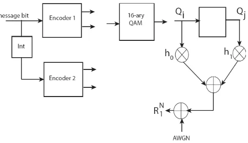
The schematic block diagram of turbo encoder is shown in Fig. 1. The scheme uses two convolutional encoders concatenated in parallel through a pseudo random interleaver. Unlike conventional code design, turbo codes are designed to reduce low weight multiplicity rather than to increase the free distance. This results in much better performance than conventional code at low and moderate SNR but somewhat weaker performance at high SNR. It is also important that interleaver should be pseudo-random interleaver in turbo code because of the reason that low weight parity sequence-1 should be matched to high weight parity sequence-2 in order to give high weight codeword to cause spectral thinning. Thus, for a given message bit, the output of encoder2 is random. Since we do not know the state of encoder-2 and its output, hence we take all possible combination of encoder-2 output. As a result, for each message bit we have four possible outputs and hence four possible next state of channel memory (with constraint length 2).
The output of turbo encoder is mapped to a symbol suitable for transmission using 16-ary Quadrature Amplitude Modulation (QAM). The channel is modeled as FIR filter with length one. The tap coefficients are denoted as
h
0,
h
1.
Q
iandQ
jare the symbol from 16-ary constellation. Encoder 1 and encoder 2 are(5, 7) recursive systematic encoder (RSC) encoder.
R
1Nis thereceived vector (output of channel).
Fig1: Encoder structure and channel Filter
[image:2.612.327.569.69.209.2]3.2
Decoder structure
Figure 2 shows the schematic diagram of turbo decoding process based on maximum a-posteriori probability (MAP). We note that decoder-1 is concatenated to decoder-2 in series through an interleaver exactly same as that used at encoder side. The input to decoder-1 is a-priori probability vector
p
aand receivedvector
R
1N. In general, decoder-1 and decoder-2 are based onMAP algorithm. In proposed method, first Decoder (D1) is based on the Super-trellis defined by Encoder-1 and channel Filter and second Decoder (D2) is based on Super-trellis defined by
Encoder-2 and channel filter.
p
a is the apriori probability.Fig. 2: The schematic diagram of Decoder structure
Turbo decoding using supertrellis structure is described as follows:
(1) Decoder-1 (using supertrellis defined by combined trellis of encoder-1 and channel filter) receives the soft input and a priori of systematic bit and yields extrinsic information.
(2) This extrinsic information after being passed through interleaver is fed to decoder-2 as input a priori.
(3) New extrinsic information is obtained from decoder-2 and after being deinterleaved is fed back to decoder-1. After complete iteration, a posteriori probability is passed through deinterleaver and sent for hard decision.
3.3
MAP algorithm
MAP decoding algorithm for the systematic convolutional code in the AWGN channel is defined by a ratio of a-posteriori probability known as log-likelihood ratio (LLR)
L(dˆk) =log[
m m k , 1
/
m m k , 0
] (3)Where
ik,m is the joint probability of message bitd
k
i
and stateS
k
m
gives the received binary sequence (soft input to decoder)R
1N observed from the timek
1
through some timek
N
and is described as) | , ( 1 , N k k m i
k Pd i S m R
(4)After writing the joint probability
ik,min terms of state metricand branch metric, the LLR in (3) can be written as
m m f k m k m k m m f k m k m k kd
L
(0, )1 , 0 ) , 1 ( 1 , 1
*
*
*
*
log
)
ˆ
(
(5)Where
kmis called forward state metric and it is the probabilityof received vector
R
1k1given the stateS
k
m
and is given as:)
|
(
R
1 1S
m
P
kk m
k
(6)The parameter
ki,mis called branch metric and is defined asm i k
,
=P
(
R
k,
S
k
m
,
d
k
i
)
(7)Backward state metric at state
S
k
m
is defined as)
|
,
(
)
|
(
R
S
m
P
R
R
1S
m
P
k N k k k N k mk
(8)3.4
Modified MAP algorithm for the
proposed decoder
The log of ratio of a posteriori probability of data bit for 1 and 0 after decoding is given by
m j j m k m j j m k N K R dL ,0,
, 1 ,
1 ) log
| (
(9) Where ) | ) , , ( , , ( 1 , , N k k m k j i mk P S d i I u mi j R
(10)
u
(
m
,
i
,
j
)
I
k Channel input at k’th instant corresponding to stateS
k
m
, input bitd
k
i
and index number j of channel filter input.By applying the Bayes‟ rule and neglecting the constant term,
] ), , , ( , , | [ * )] , , ( , , , [ * ] ), , , ( , , | [ 1 1 1 , , k k k N k k k k N k k k k j i m k R j i m u I i d m S R P j i m u I i d m S R P R j i m u I i d m S R P
(11)First term of (11) is forward state metric, second term is called branch metric and the third term is called backward state metric. Thus, these parameters are given as
)
|
(
R
1 1S
m
P
kk m
k
(12))) , , ( , , , ( , , j i m u I i d m S R
P k k k
j i m
k
(13)]
|
[
1 (1,,) ) , , ( 1 I i m f k N k I i m fk
P
R
S
(14) Forward state metric is computed by recursion as is given as:
8 1 ), , ( 1 ) , ( 1*
l l l m b k l m b k mk
(15)
v
(
m
,
l
)
I
k Input symbol of channel filter at k’th instant which can be defined by knowing stateS
k
m
and)
7
,....
2
.
1
.
0
(
,
l
l
. Note that there are eight paths merging at the next state.Similarly, backward State Metric is computed as
1 0 3 0 ) , , ( ) , , ( 1*
i j j i m k j i m f k mk
(16) Where)
,
,
(
m
i
j
f
is the next state defined by the previous state m, input bit i and index number of symbol j at the input of channel filterBranch metric is computed as
m j
u m b k Q j m Q k I j m I k m k
m j
u m b k Q j m Q k I j m I k m k
k k
y x
y x
d P
d P d L
) , 0 , (
1 2
2 , , 0 , , 2 , , 0 , ,
) , 1 , (
1 2
2 , , 1 , , 2 , , 1 , ,
* ] *
2
} ) (
) {(
exp[ .
* ] *
2
} ) (
) {(
exp[ .
log
) 1 (
) 1 ( log ) ˆ (
(18) Here
E
[
x
k,I]
m,i,j,I and E[yk,Q]
m,i,j,QoSecond term is called extrinsic information that, after being interleaved, has to be fed to the next decoder.
3.5
Table and Super-trellis structure
[image:4.612.60.288.71.192.2]Here we have tabulated the five parameters that define the Super-trellis structure. There are input to encoder, output to channel filter, present state and next state of encoder and channel filter. Super-trellis is shown in Fig. 3.
[image:4.612.353.531.111.408.2]Table 1 shows the transition of super-trellis structure where Q1, Q2, Q3 …Q16 are the points in the 16-aray QAM constellation. Its Super-trellis structure is shown in Fig. 3.
Table 1. Transition of super-trellis structure (method-1)
4.
TURBO DECODING IN ISI CHANNEL:
METHOD 2
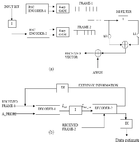
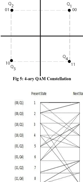
The block diagram of alternative approach for turbo decoding is shown in Fig. 4. In this approach, the output bit of ENCODER-1 and ENCODER-2 are separately mapped to different symbols using 4-ary QAM modulation scheme as shown in Fig. 5 (unlike in the previous scheme where all the four bits of encoder are mapped to single symbol using 16-ary QAM). Hence, we do not group the output of ENCODER-1 and ENCODER-2. We treat them separately. First we pass the output of ENCODER-1 through channel filter, then, we reset the filter and then, we pass the output of ENCODER-2 through channel filter. The advantage of this approach is that we obtain a simplified
[image:4.612.64.278.346.572.2]supertrellis, thereby, increasing computational speed. However, BW requirement is increased as we use only 4-ary QAM modulation scheme.
Fig 3: Super-trellis structure (Method-1)
[image:4.612.339.578.444.688.2]The decoding scheme for this approach is shown in Fig. 4(b). We note that we receive two independent frames called FRAME-1 and FRAME-2 respectively. FRAME-1 along with a-priori vector is fed to decoder-1 (based on modified MAP algorithm for joint filters such as encoder-1 and channel filter). A-priori value of message bit is assumed to be 0.5 for 0 and 1 bit each. The output of DECODER-1 is the updated value of a-priori information which is to be interleaved to be used with the interleaved date from FRAME-2. Thus, these two vectors are the input to the DECODER-2. The output of DECODER-2 is modified information about a priori probability of message bits. This extrinsic information is passed to the first decoder in the next iteration.
[image:5.612.340.553.177.403.2]Thus after each iteration, the value of a priori gets updated. After a desired iteration, this information at the decoder out is used to obtain the estimate of the message bits. Table 2 enlists all the possible states of the joint filter (Convolutional encoder plus channel filter). First column shows the possible present states of joint filter.
Fig 5: 4-ary QAM Constellation
Fig 6: Super-trellis Structure (Method-2)
We note that depending input bit, there can be only two possible states of the joint filter when the present state of RSC encoder is 00. The next state of the filter is obtained by having two possible inputs. The state diagram of the joint filter is shown in Fig. 6 Continuous line corresponds to bit 0 and dotted line corresponds to bit 1.
Table 2. Transition of super-trellis structure (method-2) showing preset state, next state, input and output
5.
SIMULATION RESULT
In order to assess the performance of the proposed method, we focus on two-tap channels. Specifically we consider an equivalent discrete ISI channel with taps
h
0
0
.
93
,h
1
0
.
25
.We have taken simulation results for two cases. In first case, by using linear equalizer, ISI effect has been removed and turbo decoding has been done in conventional manner. In second case, two methods have been proposed and Super-trellis model combining encoder and channel filter has been presented and result is compared with sub optimal technique. The result is found to be much better. For all cases, the generator matrix of RSC encoder considered for simulation is
)
(
D
G
= [12 2
1
1
D
D
D
]
and rate of encoder is taken to be ¼. Constraint length=3. For the sake of simulation, we have considered trellis without termination. The modulation technique used is 16-ary QAM for Turbo decoding in ISI channel (method-1) and for method-2, modulation ary QAM.Hence for 16 QAM constellation and 4-ary QAM constellation
(1)
2 0
2
/
av bP
N
E
[image:5.612.83.257.283.662.2]2
[image:6.612.57.284.78.302.2]
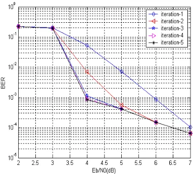
= variance of noise (one dimensional)Fig 7: BER performance (Method-1)
(2)
0 ) _ / 1 ( 0 /
N
c E rate code N
b
E (For BPSK)
For the proposed method-1, the simulation results are shown in Fig. 7 for different iterations. The plots have been obtained for BER as a function of
E
b/
N
0. This can be clearly observed thatwith increase in the number of iterations, BER performance of decoding scheme improves due to reduction in BER. The performance results for the Method-2 are shown in Fig. 8. Here also we note that the BER performance is significantly improved with increase in the number of iterations. Moreover, the method is observed to outperform the Method-1 in the sense that the BER performance is obtained at the lower SNR. A sub-optimal approach is presented in Fig. 9. Results are compared in Fig.10 and it is shown, that the performance of super-trellis Method-2 is far better than both super-trellis Method-1 and suboptimal decoding.
Fig 8: BER Performance (METHOD-2)
[image:6.612.360.551.87.259.2]Fig. 9: Turbo BER performance (sub-optimal approach). Equalizer used is linear Equalizer
Fig 10: Performance Comparison
6.
CONCLUSION
[image:6.612.346.524.309.478.2] [image:6.612.51.283.497.677.2]7.
REFRENCES
[1] A. Glavieux, C. Loat, nad J. Labat, “ Turbo Equalization over Frequency Selective Channel,” in Proc. Int. Symp. Turbo Codes and Related Topics, Best France, pp. 96-102, Sep. 1997.
[2] C. Berrou, A. Glavieux, P. Thitimajshima, “Near Shannon Limit Error Correcting Coding and Decoding: Turbo Codes,” in proc. IEEE Intl. Conf. Commun., (Geneva), pp. 1064-1070, May 1993.
[3] C. Douilard, M. Jezequel, C.Berrou, A. Picart, P. Didier, and A. Glavieux, “Iterative correction of intersymbol interference: Turbo-equalization,” European Transaction on Telecommunications, vol. 6, pp. 507-511, Sep.-Oct. 1995.
[4] C. E. Shannon, “Communication in the presence of Noise,” Proc. IRE. VOL. 37, no. 1, pp. 10-21, Jan. 1949.
[5] D. Raphaeli and Y. Zarai, “Combined turbo equalization and turbo decoding,” IEEE Commun. Lett., vol. 2, pp. 107-109. Apr. 1998.
[6] M. Vedat Eyuboglu and S. U. H Qureshi, “Reduced State Sequence Estimation with Set Partioning and Decision Feedback,” IEEE Trans. on Commun, vol. 36, no. 1, pp. 13-20, Jan. 1988.
[7] M. Vedat Eyuboglu and S. U. H Qureshi, “Reduced-State Sequence Estimation for Coded Modulation on Intersymbol Interference Channels,” IEEE J. on Select. Areas in Commun., vol. 7, no. 6, pp. 989-995, Aug. 1989. [8] John G. Proakis, 2000 Digital Communications.
McGraw-Hill, Fourth edition.
[9] M. Tomlinson, “New Automatic Equalizer Employing Modulo Arithmetic,” Electronics Letters, vol. 7, no. 5/6, pp. 138-139, March 1971.
[10] H. Harashima and H. Miyakawa, “Matched Transmission Technique for Channels with ISI,” IEEE Trans. on Commun., vol. 20, no. 4, pp. 774-780, April 1972. [11] M. Vedat Eyuboglu and G. D. Forney, Jr., “Trellis
Precoding: Combined Coding, Precoding and Shaping for ISI Channels,” IEEE Trans. on Inform. Theory, vol. 38, pp. 301-314, Mar. 1992.