Speed Range Prediction for Traffic Light Control System
Prashant Borkar
Department of CSE, GHRCE, Nagpur
Sanjeevani Jenekar
Department of ETRX, PCE, Nagpur
ABSTRACT
This paper discuses a proposed systems for acquiring the next intersection timing and generating the required speed at current intersection to cross next intersection without stopping at it. The system is speed module for next intersection prediction embedded in intelligent traffic light control system at intersection. It can also be designed for GPS based navigation system. For efficiently predicting the time and speed required for crossing next intersection without stopping at it centralized approach is taken into account, the distance between current intersection and next intersection and traffic signal timings of next intersection are considered as input to the system. The traffic signal timings are more on highway than on city road. System then generates the required speed in range to cross next intersection without stopping at it. Speed generated by the system is in specified range like 32Km/Hr to 40 Km/Hr. Also it can’t exceed the speed limit of road.
Keywords
Traffic congestion, Intersection, Traffic signal, required speed.
1.
INTRODUCTION
As the number of vehicle in urban areas is ever increasing, it has been a major concern of city authorities to facilitate effective control of traffic flows in urban areas [6]. Especially in rush hours, even a poor control at traffic signals may result in a long time traffic jam causing a chain of delays in traffic flows and also CO2 emission. Vehicle’s engine idling time consumes more fuels and releases more CO2 than the vehicle in motion states. Thus if vehicle’s idling time can be reduced, the amount of CO2 emission can be decreased [5]. Poor traffic lights control is believed to account for longer intersection waiting time, thus suitable traffic lights control scheme is crucial for reducing CO2 emissions. The total amount of accumulated delay time in a city due to waiting at signal stops is enormous if it is counted on an annual basis.
Traffic signal system is broadly categorised as static and dynamic systems. Static systems refer to traditional pre-timed system. Where the timings of the traffic controller is repeated throughout the day and are found to be same. However during off-peak times, traffic on major roadways often stop when there is little or no traffic on the cross streets. On contrary during peak hours the cycle timings don’t adjust to the traffic flow thus creating traffic jams at the intersections.
Also no one like to stop waiting at intersection, spending too much time at intersection may leads to driving stress. In many cities, these rising demands cannot be counteracted by further extending the existing road infrastructure giving a special importance to the efficient use of the existing network. In this respect, traffic lights are a vital factor since good control strategies are often capable of improving the network-wide traffic flows. To reduce the waiting time of vehicles at traffic signals is to reduce consumption of fuel and man-hours, thus it is significant to control the traffic signals in an effective manner. In the remainder of paper, an effective time management plan is
proposed where the timings of next intersection are predicted at current intersection and accordingly required speed is generated in range to cross next intersection without stopping at it, so that the effective waiting time at the intersection and corresponding traffic congestion can be reduced too much extent. In ideal case no one would have to wait at intersection.
2.
EXISTING INTELLIGENT TRAFFIC
LIGHT CONTROL SYSTEMS
Before moving on to the proposed plan it is necessary to consider some of the existing systems and architectures. In general the systems are centralised control and decentralized controls also there are some systems which are Hybrid. Holger Prothmann et. Al in [1] developed organic computing approach to develop a decentralized traffic control system and compared its impact on traffic flow with a conventional system. "The organic approach is based on industry-standard traffic light controllers,” These have been adapted to have an observer/controller architecture that allows the traffic light to respond to traffic flow and to pass on information to the other traffic lights on neighbouring roads. In the case of an urban traffic system, the sensors would be closed-circuit TV cameras mounted on road gantries and other places while the controllers, or actuators, would be traffic lights, which can effectively start and stop the flow of traffic.
Liu et al in [7] developed traffic controller for a single intersection based on the people’s strategic decision process to the multi-phase signal traffic control. The inputs to the controller were the queue lengths and the differences between the current queue lengths and the ones in next phase lanes. The outputs of one were extending green time of the current phases or changing into the succession phases. Liu et al. in [8], proposed a hierarchical fuzzy control method for arterial coordinated control. Its fundamental principle was to use hierarchical structure and fuzzy theory to solve real time coordinated control problems of traffic trunk road. Based on cycle length provided by a coordinator, it adjusted the splits of all approaches on line by using fuzzy control methods. Traffic volumes detected first then the cycle length and splits were determined by using fuzzy control method. The goal of the coordinator and subsystems was to minimize the queue length. Simulation results shown that it could shorten the queue, and reduce total traffic delay. Fuqiang Zou et al. in [13] develop fuzzy theory based traffic signal optimization for a single intersection is designed and presented based on Wireless Sensor Network. Where single-axis magnetic sensors are used to detect traffic flow and then transmitted by wireless sensor network. The system results in dynamically adjust the delay for green light and change the cycle of signal light, according to real-time traffic flow.
flow rate and real-time traffic volume of all lanes, and outputs were cycle length and green time of every phase. System has been implemented for an isolated intersection. Wiering et al in [10-11]. utilized multi-agent reinforcement learning algorithm to train traffic signal controller. The goal is to minimize the overall waiting time of cars in a city.
An adaptive real-time traffic signal control system referred to as RHODES [2], is a "dynamic network loading" model that captures the slow-varying characteristics of traffic. These characteristics pertain to the network geometry and the typical route selection of travellers. In general the system takes as input detector data for real-time measurement of traffic flow, and “optimally” controls the flow through the network. The system utilizes a control architecture that (1) decomposes the traffic control problem into several sub problems that are interconnected in an hierarchical fashion, (2) predicts traffic flows at various levels (individual vehicles and platoons) (3) allows various optimization modules for solving the hierarchical sub problems, and (4) utilizes a data structure and computer/communication approaches that allow for fast solution of the sub problems. Based on the slow-varying characteristics of the network, estimates of the load on each particular link, in terms of vehicles per hour, can be calculated. RHODES then allocates "green time" for each pattern and phase.
[image:2.595.59.284.484.575.2]Xiangjie Kong et. Al in [3] develops architecture that includes two layers - the coordination layer and the control layer. Public cycle time, splits, inbound offset and outbound offset are calculated in the coordination layer. Public cycle time is adjusted by fuzzy neural networks (FNN) according to the traffic flow saturation degree of the key intersection. Splits are calculated based on historical and real-time traffic information. Offsets are calculated by the real-time average speeds. The control layer determines phase composition and adjusts splits at the end of each cycle. The target of this control strategy is to maximize the possibility for vehicles in each direction along the arterial road to pass the local intersection without stop while the utility efficiency of the green signal time is at relatively high level.
Fig 1: Sketch map of urban arterial road
Green wave control coordinates traffic signals of adjacent intersections on arterial road to make vehicles driving by a certain speed meet no or less red lights. In other word, traffic signals of adjacent intersections become green one by one according to a certain time sequence in a direction, like a rolling “green wave”.
One approach which has gained a lot of interests in recent years is Vehicular Ad hoc Networks (VANETs). N.MASLEKAR el al. in [12] developed a dynamic system based on car to car communication. This system reduces the waiting time of the vehicles at the intersection along with the reduction in queue length. The simulation results show that system obtain a better the level of service (LOS) in terms of the average waiting time at the intersections.
3.
PROPOSED PLAN OF WORK
Based on the literature survey the proposed approach can be added as an extension part to the existing infrastructure. This section describes the proposed system that is Next intersection prediction module for intelligent traffic light control system. The proposed plan of work is centralized static approach in which all the intersections are centrally connected and static time (time for which lights at intersection are green or red) is provided as input to the intelligent traffic light control system in advance and according to that required speed is generated in range at current intersection to cross next intersection without stopping at it. All the traffic signal timings at particular intersection are considered according to signal timings of Nagpur city, India. The traffic signal timings at intersection may wary from city to city also all the calculations are done according to intersection timings of Nagpur city.
3.1
Traffic Signal Timings
This is the very important aspect to be considered while designing proposed system where in the timings for which particular traffic signal is green or red are preloaded into traffic signal control box (refer to Figure 2 and 3) and these timings are fixed throughout the day and we are assuming here that the traffic signals are centrally connected that is once the main system is initialised the entire traffic signals of particular city are start at a time. If there are any updates in traffic light timings then new timings are to be loaded into traffic signal control box for particular intersection or more than one. Generally traffic signal timings are to be updated because of several festivals or certain events such as cricket match etc.
Fig 2: Normal Traffic signal timings (Intersections on city road)
[image:2.595.291.546.490.640.2]The figure 2 refers to intersection timings of city intersection which come on city road. Here we see that all have to wait at intersection for equal time duration and also green timings for all 4 sides are same that is 22 sec.
Fig 3: Increased traffic signal timings on highway
The fig. 3 refers to intersection which comes on highway; from the figure we can see that for traffic on highway the green timing i.e. 27 sec and waiting time that is red= 70 sec. Compared to green timing = 17 sec and red time = 80 sec on city road. This is because due to more percentage of traffic on highway road as compared to city road. Also the timing provided for various traffic signals are may be different or we can even provide the timings according to rush for particular time of the day. Ex. Traffic intensity is very much high during 9 to 11 am and 4-8 pm as it office, school, college timings etc. So for this particular time period the traffic light timings can be increase by few more seconds to avoid congestion.
3.2
Neighbouring Intersections and
Approximate calculations for generating
required Speed to cross next intersection
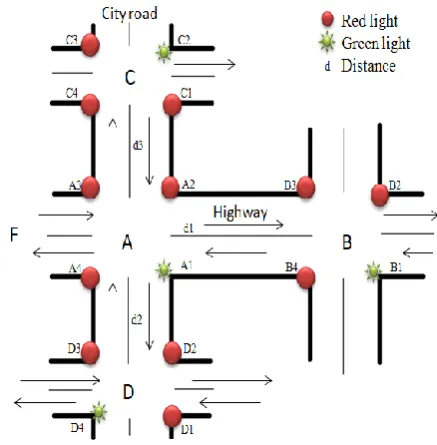
[image:3.595.59.282.77.285.2]Until now we considered only traffic signal timings for particular intersection or it can be generalised to more than one. This section of the paper provides the approximate calculations of required speed so as to cross next intersection without stopping at it. Also the required speed is in specified range so that if we follow the speed in range we don’t have to stop at intersection. Here we are considering five intersections of a particular city denoted by A, B, C, D and E. (refer to fig. 4) Traffic flow is indicated by arrows. The circle and star represents the traffic light control system. At any given intersection there are 4 traffic light controls system and every traffic light system controls the flow of traffic coming towards it as indicated by an arrow. The traffic flows from intersection A to intersection B are on highway and traffic flows from intersection C and intersection D are on normal city road. The timings for intersection A, B and F are increased as compared to intersection C and D, because they are on highway.
Fig. 4: View of 5 intersections of a particular city
Let us consider the intersection A as shown in Figure 4. Consider the flow of traffic coming towards intersection as indicated by arrow from intersection F, also d1, d2, and d3 are the distances from intersection A to intersection B, D and C respectively. In proposed plan every traffic signal light at intersection knows the traffic light timings of next signal which is ahead of it and to the right of it and to the left of it. From the fig.4 the node A.1 of intersection A knows the timings of node B.1 of intersection B and node D.4 of intersection D and node C.2 of the intersection C, here the term node refers to the traffic light control box (every intersection has 4 traffic light control box).
Moving on to the approximate calculations for next intersection prediction at current intersection and generating required speed in range to cross next intersection at current one without stopping at it. All the calculations are done according to traffic signal timings of Nagpur city, these calculations may vary from city to city.
Fig. 5: signal timings of intersection A and B
From the fig. 5 we see that at time t1 the node A1 and node B1 are on i.e. green and duration for which it remains on is 27 sec. for the traffic flow from A to B, and other timings such as 30, 50 and 80 seconds are the red timings for the traffic flow in other directions as from A to C, from B to A, and from A to D respectively similar for B. The person at A going towards B the distance he/she has to cover is 1 KM. and the speed limit of this highway is 45 KM/hr. aim is to cross intersection B without stopping at it. Now consider following cases:
Case 1: scenario where person at intersection A has to cover a distance 1 KM in 27 sec. for this the speed required is 1000/27 * 18/5 = 133.333 KM/hr which exceed the speed limit of road. Not possible
Case 2: person just reaches intersection B when it just on so he/she still have 27 sec to cross that intersection. Here person at intersection A has to cover a distance 1 KM in 27+17+27+17 = 88sec. for this the speed required is 1000/88 * 18/5 = 40.9 KM/hr. Is possible and this is the upper limit of range.
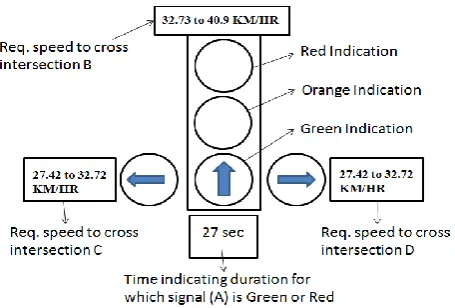
Case 3: person just reach intersection B when it going to become red (here he/she don’t have to wait at intersection B. or just for 3 to 6 sec if he/she reach earlier) here person at intersection A has to cover a distance 1 KM in 27+17+27+17+22= 110sec. here lat 22 sec. are considered for safely crossing intersection. For this the speed required is 1000/110 * 18/5 = 32.73KM/hr. This is possible and is lower limit of range. So in general if person follows speed in range 32.73 Km/hr to 40.9 KM/hr, that person doesn’t have to wait at intersection B.
Now consider the traffic flow from intersection A to intersection C and D. let us assume the distance d2 and d3 be 0.8 KM. and at time t1 the node D4 and node C2 is on i.e. green. First consider the traffic flow from A to D. at t1 timings of intersection D will look like this
The person at A going towards D the distance he/she has to cover is 0.8 KM. and the speed limit of this city road be 40 KM/hr. Aim is to cross intersection D without stopping at it. Now consider following cases:
Case 1: scenario where person at intersection A has to cover a distance 0.8 KM in 22 sec. for this the speed required is 800/22 * 18/5 = 130.9 KM/hr which exceed the speed limit of road. Not possible
Case 2: person just reaches intersection D when it just on so he/she still have 22 sec to cross that intersection. Here person at intersection A has to cover a distance 0.8 KM in 22+22+22+22 = 88sec. for this the speed required is 800/88 * 18/5 = 32.72 KM/hr. Is possible and this is the upper limit of range.
Case 3: person just reach intersection D when it going to become red (here he/she don’t have to wait at intersection B. or just for 3 to 6 sec if he/she reach earlier) here person at intersection A has to cover a distance 0.8 KM in 27+22+22+22+17= 105sec. here lat 17 sec. are considered for safely crossing intersection. For this the speed required is 1000/105 * 18/5 = 27.42KM/hr. This is possible and is lower limit of range. So in general if person follows speed in range 27.42 Km/hr to 32.72 KM/hr, that person doesn’t have to wait at intersection D. similar calculations for intersection C.
If any existing traffic signal timings optimization approach is considered then in such cases the current intersection will first acquire the traffic signal timings of neighboring intersections. These timings may vary throughout the day in accordance with traffic density conditions. Based on acquired timings and distance in-between intersections the speed range is forecasted at the intersection so that if n user follows the speed range then there will be substantial reduction in average waiting time at the intersection.
4.
PREDICTIVE TRAFFIC LIGHT
CONTROL SYSTEM AT
INTERSECTION
[image:4.595.315.543.492.646.2]The above mentioned system can be look like this at any intersection.
Fig. 7: Predictive traffic light control system at A
[image:4.595.64.285.578.738.2]4.1 Advantages
In ideal case if everyone follows the system then no one has to wait at intersection.
There will be sufficient reduction in average waiting time at intersection.
There are fewer accidents because the platoons of vehicles arrive at each signal when it is green, thereby reducing the possibility of red signal violations.
By using above mentioned system vehicle’s idling time can be reduced, the amount of CO2 emission can be decreased
Traffic flow are more smoothly, often with an improvement in capacity
Vehicle speeds are more uniform because there is no incentive to travel at excessively high speeds to reach a signalized intersection within a green interval that is not in step. Also, the slow driver is encouraged to speed up in order to avoid having to stop for a red light.
4.2 Further Considerations
The system won’t be applicable to certain events such as festivals, sport matches etc. the system may not work properly due to sudden rush on path.
If isolated intersections are considered then in such cases there may not be any communication in-between intersections.
Cost of applying this approach at signalized intersection may be significantly high due to addition display for speed range forecasting to n users at intersection.
5.
CONCLUSION
The improvement of urban traffic condition is largely dependent on the various modern techniques of traffic management and control. Advanced traffic signal controllers and control system contribute to the improvement of the urban traffic problem. The proposed plan for next intersection prediction at current one and then generating the required speed to cross next intersection without stopping at it is discussed in this paper. The primary goal is to minimize the waiting time at the intersection and alternately having smooth flow of traffic. By using above mentioned system vehicle’s idling time can be reduced, the amount of CO2 emission can be decreased. This approach can be an extension part to existing traffic signal timings optimization approaches.
For the future work we will consider the scenario more complicated also traffic light timings are continuously changing according to traffic flow and the generating the required speed to cross next intersection. We can also implement this approach at GPS based navigation device.
6. REFERENCES
[1] Holger Prothmann, Jürgen Branke and Hartmut Schmeck “Organic traffic light control for urban road networks ” Int. J. Autonomous and Adaptive Communications Systems, Vol. 2, No. 3, 2009.
[2] Pitu Mirchandani, Fei-Yue Wang “RHODES to Intelligent Transportation Systems” 1541-1672/05/ © 2005 IEEE. IEEE INTELLIGENT SYSTEMS
[3] Xiangjie Kong, Guojiang Shen, Feng Xia, and Chuang LinUrban. “Arterial Traffic Two-direction Green Wave Intelligent Coordination Control Technique and Its Application” International Journal of Control, Automation, and Systems (2011) 9(1):60-68
[4] W. Wen. “A dynamic and automatic traffic light control expert system for solving the road congestion problem” 2007 Elsevier Ltd. All rights reserved. doi:10.1016/j.eswa.2007.03.007. science direct a Expert Systems with Applications 34 (2008) 2370–2381
[5] Chunxiao LI, Shigeru SHIMAMOTO. “A Real Time Traffic Light Control Scheme for Reducing Vehicles CO2 Emissions” The 8th Annual IEEE Consumer Communications and Networking Conference - Emerging and Innovative Consumer Technologies and Applications.
[6] Chen Xiao-feng, Shi Zhong-ke, Zhao Kai “Research on an Intelligent Traffic Signal Controller” 0-7803-8125-4/03 © 2003 IEEE
[7] Liu Zhiyong, et al. A Multi-phase Fuzzy Control Method Used for Single Intersection. Information and Control, 1999, 28(6): pp. 453-458
[8] Liu Zhiyong et al. “Hierarchical Fuzzy Control for Urban Traffic Trunk Roads.” Journal of Highway and Transportation Research and Development, 1997, 14(3): pp. 17-23.
[9] Dong Chaojun, Liu Zhiyong, et al. “Urban Traffic Signal Timing Optimization Based on Multi-layer Chaos Neural Networks Involving Feedback,” Proc. Of First International Conference on Natural Computation, ICNC 2005, pp. 340-344
[10] M. Wiering. “Multi-Agent Reinforcement Learning for Traffic Light Control. Machine Learning,” Proc. of the Seventeenth International Conference (ICML'2000), pp. 1151-1158
[11] M. Wiering, et al. “Intelligent Traffic Light Control,” Technical Report UU-CS-2004-029, University Utrecht, 2004.
[12] N.MASLEKAR et al. “VANET based Adaptive Traffic Signal Control,” IEEE 2011.