© 2016, IRJET | Impact Factor value: 4.45 | ISO 9001:2008 Certified Journal | Page 421
A Seven Level Inverter using a Solar Power Generation System
Nisha Xavier
1, Sabeena Salam
2, Remna Radhakrihnan
31
Mtech Student, Department of Electrical Engineering, KMEA Engineering College, Edathala, Kerala, INDIA
2Assistant Professor, Department of Eletrical Engineering, KMEA Engineering College, Edathala, Kerala, INDIA
3
PHD Research Shcolar, Department of Electrical Engineering, CUSAT, Kerala, INDIA
---***---Abstract –
This paper proposes a new seven level inverter
with a solar power generation system, which is composed of a dc power converter and a new seven level inverter. The dc-dc power converter integrates a boost converter and a transformer to convert the output voltage of the solar cell array into independent voltage sources with multiple relationships. The most commonly used solar cell model is introduced and the generalized PV model using Mat lab/simulink is developed. Taking the effect of solar intensity and cell temperature, the characteristics of PV model are simulated. This model can be used for analysis of PV characteristics and for simulation with Maximum power point tracking algorithms. This new seven level inverter is configured using a capacitor selection circuit and a full bridge power converter. The capacitor selection circuit converts the two output voltage sources of dc/dc power converter into a three level dc voltage, and the full bridge converter further converts this three level dc voltage into seven level ac voltage. The proposed system generates a sinusoidal output current that is in phase with the utility voltage and is fed into the utility.
Key Words: Maximum power point tracking (MPPT), pulse
width modulation technique (PWM), photovoltaic (PV), multilevel inverter.
1. INTRODUCTION
The solar energy is becoming more important since it produces less pollution and the cost of fossil fuel energy is rising, while the cost of solar arrays is decreasing. The growing energy demand coupled with the possibility of reduced supply of conventional fuels, along with growing concerns about environmental preservation, has driven research and development of alternative energy sources that are cleaner, renewable and that produce little environmental impact. Among the alternative sources the electrical energy from PV is currently regarded as the natural energy source more useful, since it is free, abundant, and clean, distributed over the earth and participates as a primary factor of all other processes of energy production on earth.
The power conversion interface is more important to grid connected solar power generation systems because it converts the dc power generated by a solar cell array into ac power and feeds this ac power into utility. An inverter is necessary in the power conversion interface to convert the
dc power into ac power. Since the output voltage of solar
cell
array is low, dc/dc power converter is used in small capacity solar power generation system to boost the output voltage so it can match the dc bus voltage of the inverter. A filter inductor is used to process the switching harmonics of an inverter, so the power loss is proportional to the amount of switching harmonics. The control circuit not only provides PWM signals to switches of two power stages, but also traces maximum PV module energy as well as real time grid detection and protection. The efficiency of conventional boost converter is restricted by duty ratio for higher output voltage. Theoretically, when duty ratio is closed to unity the voltage gain will be infinity.The conventional multilevel inverter topologies include the diode clamped, the flying capacitor and the cascade H-bridge types. Diode clamped and flying capacitor multilevel inverters use capacitors to develop several voltage levels. But it is difficult to regulate the voltage of these capacitors. In both the diode clamped and flying capacitor topologies 12 power electronic switches are used for seven level inverters. The new seven level grid connected inverter contains only six power electronic switches.
© 2016, IRJET | Impact Factor value: 4.45 | ISO 9001:2008 Certified Journal | Page 422
switched at high frequency at any time, the switching powerloss is reduced and the power efficiency is improved.
1.1 Photovoltaic System
A Photovoltaic (PV) system directly converts sunlight into electricity. The basic device of a PV system is the PV cell. Cells may be grouped into form panels or arrays. The voltage and current available at the terminals of a PV device may directly feed small loads such as lighting systems and DC motors. A Photo voltaic cell is basically a semiconductor diode whose p– n junction is exposed to light. Photovoltaic cells are made of several types of semiconductors using different manufacturing processes. The incidence of light on the cell generates charge carriers that originate an electric current if the cell is short circuited.
Fig-1: Equivalent circuit of a PV cell
Fig 1 shows the equivalent circuit of a PV cell. In the figure the PV cell is represented by a current source in parallel with a diode. 𝑅𝑠 and 𝑅𝑝 represent series and parallel resistance respectively. The output current and voltage from PV cell are represented by V and I.
The I-V characteristics of the solar cell circuit can be sets by the following equations. The current through diode is given by:
ID = IO [exp (q (V + I RS)/KT)) – 1] (1) While, the solar cell output current:
I = IL – ID – Ish (2) I = IL – IO [exp (q (V + I RS)/KT)) – 1] – (V + IRS)/ Rsh (3)
Where,
I: Solar cell current (A)
IL: Light generated current (A) IO: Diode saturation current (A) q: Electron charge (1.6×10⁻¹⁹ C) K: Boltzman constant (1.38×10⁻²³ J/K) T: Cell temperature in Kelvin (K) V: solar cell output voltage (V) Rs: series resistance (Ω) Rsh: shunt resistance (Ω)
Fig-2: Maximum Power Point (Vmp, Imp)
Characteristic I–V curve of a practical PV device and the three remarkable points: short circuit (0, Isc), MPP (Vmp, Imp) and open circuit (Voc, 0).
1.2 MPPT Technique
Perturb & Observation algorithms are widely used in MPPT because of their simple structure and the few measured parameters which are required. They operate by periodically perturbing (i.e. incrementing or decrementing) the array termed voltage and comparing the PV output power with that of the previous perturbation cycle. If the power is increasing, the perturbation will continue in the same direction in the next cycle, otherwise the perturbation direction will be reversed. This means the array terminal voltage is perturbed every
MPPT cycle, therefore when the P&O is reached, the P&O algorithm will oscillate around it resulting in a loss of PV power, especially in cases of constant or slowly varying atmospheric conditions. This problem can be solved by improving the logic of the P&O algorithm to compare the parameters of two preceding cycles in order to check when the P&O is reached, and bypass the perturbation stage.
© 2016, IRJET | Impact Factor value: 4.45 | ISO 9001:2008 Certified Journal | Page 423
method may suffer from fast changes in environmentalconditions.
Fig-3 Flowchart of the P&O Algorithm.
2.CIRCUIT CONFIGURATION
The proposed solar power generation system composed of a solar cell array, a dc–dc power converter, and a new seven-level inverter. The solar cell array is connected to the dc–dc power converter, and the dc–dc power converter is a boost converter that incorporates a transformer with a turn ratio of 2:1. The dc–dc power converter converts the output power of the solar cell array into two independent voltage sources with multiple relationships, which are supplied to the seven-level inverter. This new seven-level inverter is composed of a capacitor selection circuit and a full-bridge power converter, connected in a cascade.
Fig-4 Proposed solar power generation system
The power electronic switches of capacitor selection circuit determine the discharge of the two capacitors while the two capacitors are being discharged individually or in series. Because of the multiple relationships between then
voltages of the dc capacitors, the capacitor selection circuit outputs a three-level dc voltage. The full-bridge power converter further converts this three-level dc voltage to a seven-level ac voltage that is synchronized with the utility voltage. In this way, the proposed solar power generation system generates a sinusoidal output current that is in phase with the utility voltage and is fed into the utility, which produces a unity power factor. This new seven-level inverter contains only six power electronic switches, so the power circuit is simplified.
2.1 DC-DC Power Converter
The DC–DC power converter incorporates a boost converter and a current-fed forward converter. The boost converter is composed of an inductor LD, a power electronic switch SD1, and a diode, DD3. The boost converter charges capacitor C2 of the seven-level inverter. The current-fed forward converter is composed of an inductor LD, power electronic
switches SD1 and SD2, a transformer, and diodes DD1 and DD2. The current-fed forward converter charges capacitor C1 of the seven-level inverter. The inductor LD and the power electronic switch SD1 of the current-fed forward converter are also used in the boost converter.
When SD1 is turned ON. The solar cell array supplies energy to the inductor LD. When SD1 is turned OFF and SD2 is turned ON. Accordingly, capacitor C1 is connected to capacitor C2 in parallel through the transformer, so the energy of inductor LD and the solar cell array charge capacitor C2 through DD3 and charge capacitor C1 through the transformer and DD1 during the off state of SD1. Since capacitors C1 and C2 are charged in parallel by using the transformer, the voltage ratio of capacitors C1 and C2 is the same as the turn ratio (2:1) of the transformer. Therefore, the voltages of C1 and C2 have multiple relationships. The boost converter is operated in the continuous conduction mode(CCM).
© 2016, IRJET | Impact Factor value: 4.45 | ISO 9001:2008 Certified Journal | Page 424
2.2 Seven Level Inverter
As seen in Fig. 4, the seven-level inverter is composed of a capacitor selection circuit and a full-bridge power converter, which are connected in cascade. Operation of the seven-level inverter can be divided into the positive half cycle and the negative half cycle of the utility. For ease of analysis, the power electronic switches and diodes are assumed to be ideal, while the voltages of both capacitors C1 and C2 in
the
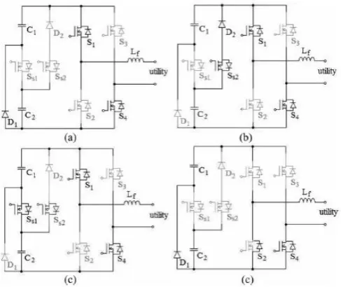
capacitor selection circuit are constant and equal to Vdc/3 and 2Vdc/3, respectively.Since the output current of the solar power generation system will be controlled to be sinusoidal and in phase with the utility voltage, the output current of the seven-level inverter is also positive in the positive half cycle of the utility. The operation of the seven-level inverter in the positive half cycle of the utility can be further divided into four modes, as shown in Fig.5.
Fig-5.Operation in the positive half cycle (a) mode 1 (b) mode 2 (c) mode 3 (d) mode 4
Mode 1: The operation of mode 1 is shown in Fig. 5(a). Both SS1 and SS2 of the capacitor selection circuit are OFF, so C1 is discharged through D1 and the output voltage of the capacitor selection circuit is Vdc/3. S1 and S4 of the full-bridge power converter are ON. At this point, the output voltage of the seven-level inverter is directly equal to the output voltage of the capacitor selection circuit, which means the output voltage of the seven-level inverter is Vdc/3.
Mode 2: The operation of mode 2 is shown in Fig. 5(b). In the capacitor selection circuit, SS1 is OFF and SS2 is ON, so C2 is discharged through SS2 and D2 and the output voltage of the capacitor selection circuit is 2Vdc/3. S1 and S4 of the full-bridge power converter are ON. At this point, the output voltage of the seven-level inverter is 2Vdc/3.
Mode 3: The operation of mode 3 is shown in Fig. 5(c). In the capacitor selection circuit, SS1 is ON. Since D2 has a reverse bias when SS1 is ON, the state of SS2 cannot affect the current flow. Therefore, SS2 may be ON or OFF, to avoiding switching of SS2. Both C1 and C2 are discharged in series and the output voltage of the capacitor selection circuit is Vdc. S1 and S4 of the full-bridge power converter are ON. At this point, the output voltage of the seven-level inverter is Vdc.
Mode 4: The operation of mode 4 is shown in Fig. 5(d). Both SS1 and SS2 of the capacitor selection circuit are OFF. The output voltage of the capacitor selection circuit is Vdc/3. Only S4 of the full-bridge power converter is ON. Since the output current of the seven-level inverter is positive and passes through the filter inductor, it forces the antiparallel diode of S2 to be switched ON for continuous conduction of the filter inductor current. At this point, the output voltage of the seven level inverter is zero. Therefore, in the positive half cycle, the output voltage of the seven-level inverter has four levels:
Vdc, 2Vdc/3, Vdc/3, and 0.
Fig-6.Operation in the negative half cycle
[image:4.595.40.284.333.538.2] [image:4.595.333.562.358.585.2]© 2016, IRJET | Impact Factor value: 4.45 | ISO 9001:2008 Certified Journal | Page 425
converter, so the output voltage of seven levelinverter also has four levels:
Vdc, 2Vdc/3, Vdc/3, 0, −Vdc/3, −2Vdc/3, and
−
Vdc.3. Experimental Results
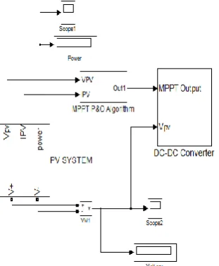
To verify the performance of the proposed solar power generation system, a prototype was developed with a controller based on the DSP chip TMS320F28035. The power rating of the prototype is 500W, and the prototype was used for a single-phase utility.
Fig 7: Simulink block diagram of solar power generation system
Simulation was done on MATLAB R2013a, the results was shown that the solar inverter has reduced harmonics.
Fig .8 Simulink model of PV cell
Fig.9 Simulink model of P & O algorithm
[image:5.595.315.553.115.328.2] [image:5.595.45.201.263.452.2]
© 2016, IRJET | Impact Factor value: 4.45 | ISO 9001:2008 Certified Journal | Page 426
Fig.11. Output voltage of seven level inverter
Fig.12.THD Waveform
4. CONCLUSION
This paper proposes a solar power generation system to convert the DC energy generated by a solar cell array into AC energy that is fed into the utility. The proposed solar power generation system is composed of a DC/DC power converter and a seven-level inverter. The seven-level inverter contains only six power electronic switches, which simplifies the circuit configuration. Furthermore, only one power electronic switch is switched at high frequency at any time to generate the seven-level output voltage. This reduces the switching power loss and improves the power efficiency. The voltages of the two DC capacitors in the proposed seven-level inverter are balanced automatically, so the control circuit is simplified. Experimental results show that the proposed solar power generation system generates a seven-level output voltage and outputs a sinusoidal current that is in phase with the utility voltage, yielding a power factor of unity. In addition, the proposed solar power generation
system can effectively trace the maximum power of solar cell array.
REFERENCES
[1] Buticchi, G.; Barater, D.; Lorenzani, E.; Concari, C.; Franceschini, G. A nine-level grid-connected
converter topology for single-phase transformerless PV systems. IEEE Trans. Ind. Electron. 2014, 61, 3951–3960.
[2] Z. Zhao, M. Xu,Q. Chen, J. S. Jason Lai, and Y. H. Cho, “Derivation, analysis,and implementation of a boost– buck converter-based high-efficiency pv inverter,” IEEE Trans. Power Electron., vol. 27, no. 3, pp. 1304– 1313,
[3] K. Hasegawa and H. Akagi, “Low-modulation-index operation of a five level diode-clamped pwm inverter with a dc-voltage-balancing circuit for a motor drive,” IEEE Trans. Power Electron., vol. 27, no. 8, pp. 3495– 3505,Aug. 2012
[4] N. A. Rahim, K. Chaniago, and J. Selvaraj, “Single-phase seven-level grid-connected inverter for photovoltaic system,” IEEE Trans. Ind. Electr. vol. 58, no. 6, pp. 2435– 2443, Jun. 2011.
[5] Jinn-Chang Wu, Member, IEEE, and Chia-Wei Chou, “Solar Power Generation system with a Seven-Level Inverter,” IEEE Transactions on Power Electronics, vol. 29, no. 7, July 2014
[6] Arango, E.; Ramos-Paja, C.A.; Calvente, J.; Giral, R.; Serna, S. Asymmetrical interleaved DC/DC switching converters for photovoltaic and fuel cell applications— Part1: Circuit generation, analysis and design. Energies 2012, 5, 4590–4623.
[7] Walker, G.R.; Sernia, P.C. Cascaded DC–DC converter connection of photovoltaic modules. In Proceedings of the 33rd Annual Power Electronics Specialists
Conference,Cairns, Queensland, Australia, 22–27 June 2002; pp. 24–29.
[8] E. Pouresmaeil, D. Montesinos-Miracle, O. Gomis- Bellmunt, ”Control Scheme of Three-Level NPC Inverter for Integration of Renewable Energy Resources Into AC Grid,“ Syst. J., Vol.6, No.2, pp.242-253, 2012. [9] K. Hasegawa, H. Akagi, “Low-Modulation-Index
Operation of a Five-Level Diode-Clamped PWM Inverter With a DC-Voltage-Balancing Circuit for a Motor Drive ,” IEEE Trans. Power Electron., Vol. 27, No. 8, pp.3495-3505, 2012
[10] J, M. Shen, H. L. Jou, J. C. Wu, “Novel Transformer- less Grid-connected Power Converter with
© 2016, IRJET | Impact Factor value: 4.45 | ISO 9001:2008 Certified Journal | Page 427
BIOGRAPHIES
NISHA XAVIER -PG Shcolar and completed B Tech in Electrical and Electronics Engineering in 2013 from SNM IMT Maliankara and presently pursuing M Tech in “Power Electronics” in KMEA Engineering College Edathala,Kerala,INDIA
SABEENA SALAM – Assistant Professor in KMEA Engineering COLLEGE EDATHALA,KERALA.She completed her B Tech in Electrical and Electronics Engineering and ME in “Power Electronics”