Particle size (/urn)
FIGURE 3.3-7 Immiscible liquid separator particle size range.
area and volume of the liquid separators for large flow applications, but they are the devices with highest purchase and operating costs.
Material of construction should not pose a major problem since most devices are available in a wide range of metals and plastics. If lower-cost metals or reinforced plastics are not acceptable and exotic metals are needed, a smaller size device such as the centrifuge may be more attractive, compromising the typical capital cost comparison of Table 3.3-1.
3.4 LIQUID-SOLID SEGREGATION 3.4-1 Gravity Settlers
TYPE I SEDIMENTATION
The settling of dilute slurries where there is little particle-to-particle interaction is commonly referred to as Type I settling. All particles settle independently; consequently, if a particle size distribution is known and the settling rate of individual particles is known, then a settler can be designed. The design method for solid-liquid gravity settlers is the same as the previously described design method for gas-liquid gravity
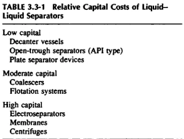
TABLE 3.3-1 Relative Capital Costs of Liquid-Liquid Separators
Low capital Decanter vessels
Open-trough separators (API type) Plate separator devices
Moderate capital Coalescers Flotation systems High capital
Electroseparators Membranes Centrifuges
Gravity decanters or API
Plate settlers
Fiber pack coalescers
Centrifuges
Flotation
Electrotreaters
Membranes
[image:1.396.105.290.473.613.2]settlers (see Section 3.2). If the terminal velocity (U,) of the smallest particle to be separated is known or can be calculated, then the overflow area (A1) can be calculated from the equation
(3.4-1)
where Qc is the volumetric flow rate of the liquid.
As for gas-liquid and gas-solid systems, the liquid depth must be sufficiently great to minimize the suspending effects of turbulent liquid flow. As discussed in Section 3.2, the particles will not be resuspended provided the flow velocity is less than about 20 times the terminal velocity. To be conservative the flow velocity should be 10 times the particle terminal velocity. Thus, the flow area (AF) is given by
(3.4-2) If the height of the basin is one-third the width,
(3.4-3)
For an example of 10 /tim particles of specific gravity = 3, the terminal velocity is 0.033 ft/s. To separate these particles and all larger particles from a water stream of 100 ftVmin (833 gal/min), the basin dimensions are calculated as follows:
In actual practice the effects of turbulence and other nonuniform flow characteristics would necessitate making the basin at least 19 ft long.
TYPE Il SEDIMENTATION
Slurries exhibiting Type II behavior are sufficiently thick and flocculent that the solids tend to settle as a mass, giving a rather sharp line of demarcation between the clear liquid overflow and the settling solids. For such systems the design is normally controlled by the thickening capability of the basin, although the basin design must be adequate to provide sufficient overflow area to clarify the liquid overflow.
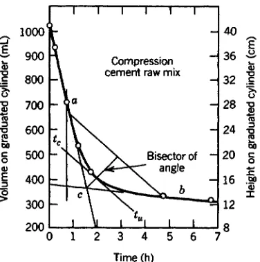
A settler for Type II slurries is normally referred to as a thickener. They are sometimes constructed as a rectangular basin; however, most often they are of circular cross-section. In the rectangular basin, solids are normally removed by a traveling syphon that moves longitudinally back and forth along the basin. In the circular design a raking mechanism is used to convey the settled solids slowly to the center of the basin where, as with the rectangular basin, a syphon is used for their removal. Figure 3.4-1 depicts a circular thickener. The feed is introduced below the liquid surface and above the sludge blanket. Density differences between the feed, clarified liquid, and settled solids cause the feed to spread laterally or radially from the feed point, producing the effect of feeding the basin uniformly across the area just above the sludge layer. The design methods most commonly used for Type II settlers and thickeners are discussed by Fitch,1 Talmadge and Fitch,2 Cremer and Davies,3 Metcalf and Eddy,4 and Clark et al.5 The methods rely on the taking of experimental data and on empirical analysis of the data to obtain a design. For this reason the recommended approach is best presented by considering a specific example. The settling data (Fig. 3.4-2) for a water-cement slurry, presented by Cremer and Davies, will be used. The important independent design parameters are as follows:
Time (h)
FIGURE 3.4-2 Settling test data utilization. Reproduced from H. W. Cremer and T. Davis, Chemical Engineering Practice, Vol. 3, Chap. 9, Academic Press, New York, 1957.
Volum
e
o
n
graduate
d
cylinde
r (mL
)
Heigh
t o
n
graduate
d
cylinde
r (cm
)
Compression cement raw mix
[image:3.396.106.294.391.580.2]Bisector of - angle
FIGURE 3.4-1 Clarifier/thickener configuration. Courtesy of Eimco Process Equipment Co. Drive motor
Feedpipe
(2)shortorms Superstructure
(2) long arms
Orive control with lood indicator
Overflow launder outlet
Superstructure
Motorized lifting device
Guide bearing Liquid level
Overflow lounder Weir
Feedpipe Feedwell
Arm
Overflow lounder
Blodes Cone scroper
Discharge cone Steel tonk
Concrete tank
QLt volumetric flow rate of water 2,625 ft3/h Qt, total volumetric flow to basin 3,150 ft3/h C0, concentration of solid in feed 32 lbm/ft3 The dependent parameters are as follows:
Xw, volume fraction of water in underflow 0.33 pM, average density of underflow 147 lbm/ft3 Q0, water overflow rate = [2625 - (525/0.667)(0.333)] 2363 ft3/h
Clark et al.5 present the method for determining the surface area large enough to prevent the rate of liquid rise from exceeding the velocity of subsidence of the sludge interface:
(3.4-4)
The subsidence velocity (K5) is obtained by measuring the slope of the plot of interface height versus time (Fig. 3.4-2). For the cement slurry V5 = 40/2 = 20 cm/h «• 0.66 ft/h. Then
Next, the area required for thickening in the bottom of the basin is determined by the method explained by Fitch, where H0 is the initial height of the slurry in the graduated test cylinder:
(3.4-5) The underflow time (tu) is determined graphically as shown in Fig. 3.4-2. For this example tu = 3.2 h.
It is recommended that this value be multiplied by a safety factory of 1.33; thus,
The diameter of the circular basin would be 113 ft. As in most thickeners the area is determined by the requirement to thicken the sludge and not by the requirement to clarify the overflow. Note that the thickener can be sized from one settling test. In practice, one should conduct a settling test in at least two different cylinder heights.
As explained by Fitch1 the depth of the sludge layer needs to be calculated. From Fig. 3.4-2 note that the time in the compression layer is about 7 — 2 = 5 h. The volumetric flow of the slurry out of the basin bottom is equal to the total flow to the basin minus the water overflow, that is (3150 - 2363) = 787 ft3/h. Knowing the flow area (10,000 ft2) and the residence time (5 h), the depth of the compression layer can be computed:
As Fitch1 indicates, the accepted procedure is to use a minimum depth of 3 ft for the sludge layer. This then makes the method conservative because more compression will be realized in a 3 ft layer than in a 0.4 ft layer.
3.4-2 Centrifugal Separators
HYDROCYCLONES
The liquid-solid hydrocyclone, shown schematically in Fig. 3.4-3, functions like a gas-solid cyclone. The hydrocyclone is also known as a hydroclone. The primary independent parameters that influence the ability of a hydrocyclone to make a separation are size and geometry of the hydrocyclone, particle size and geometry, solids loading, inlet velocity, split between overflow and underflow, density differential, and liquid viscosity. A reasonable estimate of the particle cut diameter (50% in underflow and overflow) (Ci50) is given by the following dimensionless relationship, developed initially by Bradley:6
OPERATION OF THE HYDROCYCLONE
LIQUID DISCHARGE
(D
Pressurized Slurry
enters tangential Iy ...
(2)
Slurry rotation develops
high centrifugal forces
throughout cyclone ...
(3)
Suspended solids driven
toward wall and downward
in accelerating spiral...
(4)
Liquid moves inward and
upward as spiralling vortex
[image:5.396.29.365.147.603.2]SOLIDSDISCHARGE
(3.4-6)
where Dc, Z),, and D0 are the body, inlet, and overflow diameters, respectively, n is the liquid viscosity, Rf is the fractional underflow rate, Q is the volumetric feed rate, ps and pL are solid and liquid densities, and L is the cyclone length. This equation predicts reasonable dependencies for the primary independent variables except for the cyclone diameter. The cut diameter is more nearly proportional to D, rather than D)5.
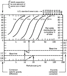
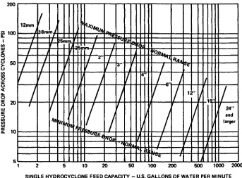
To estimate the performance of hydrocyclones, Day7 has published Fig. 3.4-4. This chart can be used to estimate the performance of hydrocyclones of various sizes and it can be used to predict the effect of specific gravity difference and liquid viscosity. Figure 3.4-5 allows prediction of capacities at various flows and pressure drops as a function of hydrocyclone size.
Equation (3.4-6) in conjunction with Figs. 3.4-4 and 3.4-5 will allow preliminary sizing of a hydro-cyclone. Sometimes this information in conjunction with vendor consultation will be adequate to determine the final sizing of a hydrocyclone, provided the solids are readily characterized and the solids concentration in the feed is steady. For applications where the solids vary widely in size, where the solids are far from spherical, where clarity of the overflow is critical, and where solids concentration in the underflow is crucial, a test program should be undertaken.
Hydrocyclones are applicable where extreme clarity of the overflow is not needed and where the separated solids are not expected to be very dry. Hydrocyclones are extremely useful where a liquid stream contains few relatively large solids that must be separated. For this situation a catch pot will suffice to capture the solids and then they can be discharged intermittently.
Discharge of the solids is a special problem with hydrocyclones. Under circumstances of a constant
Solids separation by size percent of same size in feed
U.S. standard sieve sizes
Plot solids distribution by
cumulative % of total
Base line
Base line
Particle size Giim)
[image:6.396.65.332.278.581.2]Correction Viscosity specific gravity centipoise difference correction
SINGLE HYDROCYCLONE FEED CAPACITY - U.S. GALLONS OF WATER PER MINUTE
FIGURE 3.4-5 Hydrocyclone capacity ranges versus size. From R. W. Day, Chem. Eng. Prog.y 69(9),67 (1973). Reproduced by permission of the American Institute of Chemical Engineers.
feed composition, the installation of a cone of given size will result in steady discharge of solids at a given liquid composition. However, if solids in the feed fluctuate, then the underflow will fluctuate. The conditions necessary to obtain proper discharge of underflow without plugging the hydrocyclone or getting too high a flow out the underflow must be determined experimentally. Experiments are normally necessary to determine the proper size of cone extension in order to obtain the proper split between underflow and overflow. The control of the split is a unique problem that requires careful consideration of the design. A flow control scheme can be devised to give a constant fraction of the total flow as overflow so that the volumetric flow of underflow is automatically controlled. Also, a control valve can be placed in the underflow line.
A good discussion of the hydrocyclone applications and design is given by Poole and Doyle8 and they list 193 references covering selection, operation, and design.
CENTRIFUGES
Perry's Chemical Engineers' Handbook and manufacturers* literature10"11 are excellent sources of technical
information about the selection and design of centrifuges.
Centrifuges are of two general types: (1) sedimentation and (2) filtration. The sedimentation machines apply centrifugal forces to enhance the sedimentation velocity of the solids toward a rotating, collecting solid surface; the filtration machines apply centrifugal forces to force the solid phase to collect first as a cake on a filter cloth or screen and subsequently to force the liquid through the cake and the screen. Conceptually, the sedimentation centrifuges operate analogously to the gravity settler except the gravita-tional force is enhanced from 1,000 to 20,000 times by the centrifugal acceleration. The filtration machines operate analogously to pressure or vacuum filters except the force causing the liquid to flow through the cake is a result of centrifugal forces rather than pressure forces.
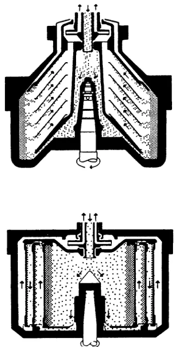
Sedimentation Centrifuges. Various sedimentation centrifuges are illustrated schematically in Figs. 3.4-6-3.4-9. The machines differ primarily in the manner in which the solids are discharged. In the solids-retaining solid-bowl centrifuge, either conical disks or cylindrical inserts are features that increase the separation area. In both types, the solids must be discharged manually by periodic opening of the bowl. In the solids-ejecting solid-bowl centrifuge, the solids collect at the periphery of the bowl and periodically
CYCLONE CAPACITY NOMOGRAPH
PRESSUR
E DRO
P ACROS
S CYCLONE
S
PS
FIGURE 3.4-6 Solids-retaining solid-bowl centrifuges: (a) bowl with conical disks and (b) bowl with cylinder-insert solids retainers. Courtesy of Alfa-Laval Inc.
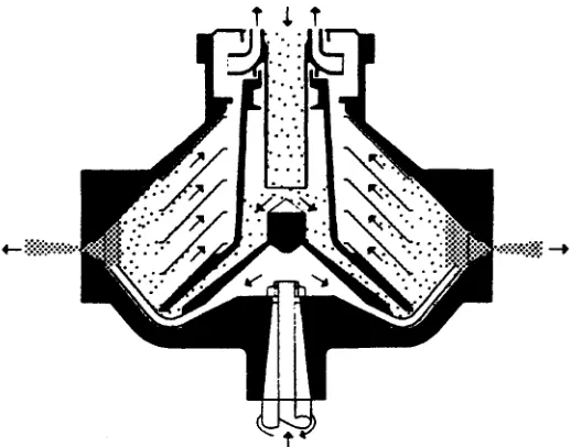
the bottom of the bowl is lowered very rapidly and the collected solids are ejected. In the nozzle solid-bowl centrifuge, the solids are discharged continuously through small nozzles. Washing can be accom-plished on these machines by injecting wash liquid between the disk stack-and the discharge nozzles. By recycling solids, the solids concentration in the nozzle effluent can be maintained at a reasonable level somewhat independent of the solids content of the feed. The decanter solid-bowl centrifuge has a helical auger conveyor operating within a rotating solid bowl. The bowl has a straight cylindrical portion and a cylindrical-conical portion ("beach"). The solids are centrifuged to the outer wall of the cylindrical section where they are conveyed out of the liquid pool up the "beach," where they drain, and out the solids discharge port. The depth of the liquid pool is controlled by the radial location of liquid discharge ports.
FIGURE 3.4-8 Nozzle solid-bowl centrifuge. The peripheral nozzles are for solids discharge. Solids are washed before discharge. Courtesy of Alfa-Laval Inc.
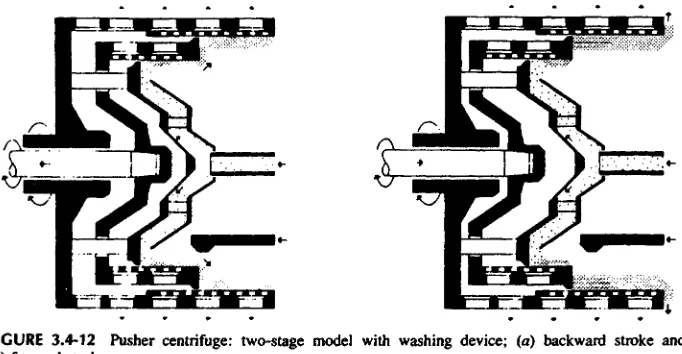
is attached to the pusher plate, and as the pusher plate oscillates back and forth the solids are pushed off the inner screen onto the outer screen and also from the outer screen into the discharge chute.
Ranges of Applicability. The suitability of a particular machine will depend strongly on the solid and liquid characteristics (liquid viscosity, density difference between liquid and solid, particle size, particle shape, percent solids in feed, and solids flowability) and on the required clarification of the liquid and the required dry ness of the solids. The solid-bowl machines are ideally suited for applications requiring liquid clarification; the order of preference is solids-retaining, nozzle, solids-ejecting, and decanter. In all these machines the solids will normally contain more than 50 vol.% liquid. The filtering machines will produce the dryest cakes. Cake liquid contents below 10 wt. % are common. However, the filtering machines will normally not produce a solids-free filtrate. Sometimes a sedimentation and a filtering centrifuge are used together to obtain the driest solids and the clearest filtrate.
[image:10.396.49.344.451.592.2]Particle size and percent solids in the feed are also key parameters that affect equipment selection. Figure 3.4-13 indicates the suitable choices for given ranges of these parameters. The filtering centrifuges will not normally handle small particles as well as sedimenting centrifiiges because of problems with filter media blinding.
FIGURE 3.4-10 Filtering vertical basket centrifuges: (a) feed and separation phase and (b) solids-dis-charging phase.
Capacities. Ultimate capacities and machine operability must be determined experimentally; however, typical ranges for various machines can be given. Table 3.4-1 gives capacity-related data for various types and sizes of sedimentation machine. Note that a tubular machine is included but not discussed here. It is simply a single rotating tube used to clarify liquids at low flow rates.
The capacities of filtering machines are even more variable than the capacities of solid-bowl machines; consequently, it is even more difficult to give an estimate of capacity. However, the data presented in Table 3.4-2 give approximate capacities as a function of machine size for a two-stage pusher. The capacities for the peeler would be somewhat less and for a basket less still. The best source of information regarding capacities are the manufacturers of the various machines.
3.4-3 lmpaction (Filtration)
FIGURE 3.4-12 Pusher centrifuge: two-stage model with washing device; (a) backward stroke and (b) forward stroke.
solids. The medium in most filtrations has only a minor effect; as solids are trapped by the medium they begin to pile up on top of each other, forming a cake of solids that actually becomes the filter medium. This is called cake filtration. In the other common filtration mechanism, called depth filtration, the solids are trapped in the pores or body of the medium.
Filtration is facilitated by establishing flow through the medium either by gravity, by applying pressure upstream of the filter medium, or by applying vacuum downstream of the filter medium. Filtration can be thought of in terms of the common engineering relationship: rate is proportional to driving force divided by resistance. For filtration, the resistance is equal to the resistance through the cake plus the resistance through the filter medium:
(3.4-4)
where QL is liquid flow rate, A is the filter area, AP is the pressure drop across the cake and medium, p. is the liquid viscosity, a is the specific cake resistance, W is the mass of accumulated dry cake solids corresponding to QL, and R is the resistance of the medium.
Particle size (Mm) 0.1 1 10 100 1000 10000 100000 Pusher
Peeler Basket Decanter Nozzle Solids-ejecting Solids-retaining
Solids (%) 0 10 20 30 40 50 60 70 80 90 100 Pusher
Peeler Basket Decanter Nozzle Solids-ejecting Solids-retaining
Source: R.'H. Perry and D. Green, Perry's Chemical Engineers' Handbook, 6th ed., McGraw-Hill, New York, 1984.
"Turbine drive, 100 lbm/h (45 kg/h) of stream at 40 lb/in.2 gauge (372 kPa) or equivalent compressed air.
^Widely variable
cMaximum volume of solids that the bowl can contain (in ft3).
Note: To convert inches to millimeters, multiply by 25.4; to convert revolutions per minute to radians per second, multiply by 0.105; to convert
gallons per minute to liters per second, multiply by 0.063; to convert tons per hour to kilograms per second, multiply by 0.253; and to convert horsepower to kilowatts, multiply by 0.746.
TABLE 3.4-1 Specifications and Performance Characteristics of Typical Sedimentation Centrifuges
Source: Courtesy of TEMA, Inc.
TABLE 3.4-2 Size and Typical Approximate Capacities for Two-Screen Pusher Centrifuges
1202 1002 802 602 452 252 352 SHS Type 1200 60 85 2900 2700 2220 9800 1000 40 75 2900 2500 2020 8200 800 25 45 2250 2100 1570 3800 600 15 33 2050 1820 1400 3000 450 8 22.5 1900 1100 1050 1800 250 350 2.5 4.5 7.7 10.5 1500 1500 850 950 800 850 900 1000 mm ton/h kW mm mm mm kg Nominal basket
Sizing of filtration equipment is impossible from a theoretical approach because of the varying nature of the solid particles. Almost all applications are determined with the aid of test work. Typical test arrangements are a vacuum leaf test, a buchner funnel, and a pressure bomb method.
A leaf test consists of a 10-12 cm diameter frame to which is attached a filter medium such as a screen or cloth. This frame is connected by tubing to a filtrate collection reservoir which is evacuated by a vacuum source. The leaf assembly is placed into a well-mixed vessel containing the slurry to be separated. Time to form various depths of filter cake and the amount of liquid passed are observed versus time and the level of vacuum applied. Potential for drying the cake is observed by removing the leaf assembly from the slurry and letting air be drawn through the cake to allow drying. A slight alternative to this approach is the use of a small Buchner funnel with an appropriate filter medium. The slurry is poured into the funnel and the time of filtration and resulting cake dryness observed. These tests can be used to determine sizing parameters for various vacuum-motivated fi It rations such as nutsche filters, rotary drum filters, pan filters, and belt filters.
A bomb test consists of a 6-25 cm2 leaf covered with appropriate filter medium and placed in a small pressure vessel containing enough slurry to form a desired amount of cake on the leaf. The quantity of filtrate liquid flowing through the cake is measured as a function of time under various pressures and the depth of cake formed is observed. This type of test can provide information for sizing pressure leaf filters or plate and frame filters. These tests are best conducted by filter vendors who have experience in translating the results to full-scale equipment.
Filtration equipment will be briefly reviewed for the following categories: batch cake filters, continuous cake filters, and clarifying filters.
BATCH CAKE FILTERS
The nutsche filter is one of the simplest designs, consisting of a vertical tank with a false bottom that is either perforated or porous and that may be covered with a cloth or screen. Slurry is fed into the vessel and separation occurs by using gravity, vacuum, or gas pressure to motivate the liquid through the media. Washing of accumulated cake is possible. This type of filter is very similar to the laboratory Buchner funnel. Most nutsche filters are self-manufactured, although the Rosenmund filter is a commercial unit of 1-10 m2 designed for closed operation with automated cake discharge.
The horizontal plate filter is a pressure filter with a number of horizontal circular drainage plates in a stack in a cylindrical shell. A filter cloth or paper is placed on each plate. Filter aid may be applied if necessary. Filtration is continued until the cake capacity of the unit is reached or the filtration rate becomes too slow owing to cake resistance. Pressure drop across the filter medium is generally designed for 50 lbf/in-2. Cake may be washed or air-blown prior to manual removal. This type of filter is flexible and easily cleaned or sterilized, but it has a high labor requirement.
The filter press was one of the most common filters in the past and is still used today. The plate-and-frame design consists of a series of rectangular plates with filter medium, usually cloth, attached to both sides with a hollow frame placed between each plate in an alternating manner to allow accumulation of cake. The plates and frames are usually hung vertically from two parallel horizontal bars or tubes and pressed together mechanically; with new larger designs a hydraulic ram is often used. Slurry is fed to the frame sections, with filtrate passing through the medium and exiting from the plate sections. Nozzles for feed and filtrate discharge are connected to manifolds with flexible tubing so that the press may be opened and spread apart for cake removal. Various nozzle configurations are used depending on the type of slurry and washing requirements. Plates and frames are constructed of metals, plastics, or wood with some designed for operating pressures up to 100 lbf/in.2.
The filter press has the advantages of simplicity, low capital cost, flexibility, ease of cleaning and media replacement, and moderate pressures. Disadvantages include high labor input to handle each plate and frame for cake discharge, frequent cloth replacement due to the handling and scraping of the cloth, and housekeeping problems that leaks or solid discharge. Some of these disadvantages are being addressed by automated mechanical systems for press opening and cake discharge. Operator exposure to process materials during the opening of the filter at each cycle limits the application to nontoxic, nonflammable materials.
TOP-OUTLET TUBULAR FILTER "HYDRASHOCK"
FIGURE 3.4-14 Tubular filter. Courtesy of the Industrial Filter and Pump Manufacturing Co.
to displace cake from the outside surface of the tubes. An example of this design is shown in Fig. 3.4-14. This system has the advantage of being a totally closed operation, which allows handling of toxic materials and low labor requirements. The blowback fluid requirements limit the ability to obtain maximum cake dryness.
Pressure leaf filters consist of flat filter elements supported inside a pressure vessel. The leaves may be circular, arc-sided, or rectangular, and they have filter medium on both faces of a durable screen frame. The vessel axis and the leaf orientation can be any combination of vertical or horizontal. Slurry is fed to the vessel body and cake accumulates on the surface of the leaves. Filtrate passes into the leaf assembly and exits via a manifold. Cake is allowed to build to a limited thickness to allow for washing or ease of discharge. Cake discharge is facilitated by sluicing with liquid sprays, vibration of the leaves, or rotation of the leaves against a knife, wire, or brush. If wet cake is allowed, a high-pressure liquid sluicing is used. With rotation of the leaves a center axis manifold and leaf support are used. Some units open the filter for cake discharge by separating the leaf assembly from the shell. Some horizontal vessels with vertical leaves use an internal conveyor to obtain dry cake removal and closed operation. Centrifugal-discharge designs consist of horizontal disks with filter elements on one side attached to a vertical hollow shaft. This filter is appropriate for closed operation on toxic materials. It is also flexible for ease of washing of cake, drying of cake with a gas purge, and a relatively dry discharge of cake due to high-speed centrifugal discharge by rotation of the vertical shaft. Some designs use a brush to aid in cake removal during the rotation for cake discharge.
C O N T I N U O U S CAKE FILTERS
Continuous cake filters are used where cake formation is rapid, solid concentration in the slurry is greater than 1 %, particle size is greater than 100 /*m, and slurry flow rate is greater than about 0.083 L/s (0.017-0.03 gal/s). Liquid viscosity is usually below 100 cP to allow good liquid flow through the cake as it forms. Some applications can compromise some of these parameters if filter aid is used and a pure cake is not the desired product.
Drain Inlet
Flow-Chamber Tube
Rotary drum filters are the most common of the continuous cake filters. Designs may be either pressure or vacuum motivated with a horizontal axis drum and a filter medium placed on the cylindrical portion of the drum supported by a backup screen or grid. Sizes range from 4 to 1000 ft2 and material of construction may be either metals or plastics. The filter operates by slowly rotating the drum in a trough of slurry with the drum from 10 to 35% submerged. An oscillating rake or agitator may be needed in the trough for rapid settling slurries. Cake forms on the outside of the drum while in the trough, and filtrate passes through the cake and is collected by a manifold system beneath the surface of the drum. As the drum rotates out of the slurry pool, air or gas is drawn through the cake, displacing the filtrate. A wash may be applied with sprays to the cake surface followed by further drying. An air or gas blowback can be applied to dislodge the cake prior to the drum rotating back through the slurry trough.
Filtrate and washes collected by the manifold system exit via a rotary valve placed in one of the drum trunnions. Drum rotation is usually in the 0.1-10 rev/min range. Various cake discharge designs are used. Scraper discharge uses a blade to deflect the cake just prior to the drum re-entry into the pool, usually assisted by an air blowback. A taut wire may be used in place of a blade. String discharge consists of many parallel endless strings or wires spaced about 1.25 cm apart. The strings separate tangentially from the drum surface, lifting the cake from the medium. The strings are separated from the cake and return to the drum surface by two small rollers. Some designs involve removal of the entire medium from the drum surface, passing it over rollers that discharge the cake and then return to the drum, often with medium washing sprays applied. A roll discharge involves a small diameter roll in close proximity to the drum and rotating in the opposite direction at a speed slightly higher than the drum. The cake on the drum adheres to the roller and is separated from the drum. A blade or wire may be used to remove the cake from the roller.
A variation of the rotary drum filter is the continuous precoat filter. This type is used for clarification of dilute slurries containing 50-5000 ppm of solids where only very thin unacceptable cakes are formed on other filters. Design is similar to the standard rotary drum with a blade discharge. Prior to feeding slurry, a precoat layer of filter aid or other solids are applied 75-125 mm thick. Slurry is then fed and solids are trapped in the outer layer of the precoat. A progressively advancing blade cuts the solids plus some of the precoat on each pass. When the blade advances to the minimum point, the operation must be suspended and the precoat re-established.
A disk filter is a vacuum filter consisting of a series of vertical disks attached to a horizontal axis shaft rotating in a pool of slurry similar to the rotary drum filter. The disks consist of several sectors of metal or plastic covered on both sides with a filter cloth. Filtrate exits from the sectors via a nipple into the center shaft. The disks are usually 40-45% submerged in the slurry trough. Wash may be applied with sprays, but this is unusual. As the sectors rotate to the discharge point, the vacuum is cut off and an air blowback helps dislodge the cake, with scraper blades directing the cake into discharge chutes positioned between the disks. This filter provides a large area with minimum floor space and has the lowest cost per unit area, and it is best used for high-volume dewatering applications.
Horizontal vacuum filters are found in two basic designs, rotary circular and belt filters. They provide flexibility in cake thickness, washing configuration, and drying time. They are effective for heavy dense solids, but they are expensive, require a large floor space, and are difficult to enclose for hazardous applications.
The rotary design is a circular pan with slurry fed across the radius of the pan and the cake discharge located about 300° around the circle using a screw discharge. Sizes range to 81 ft (25 m) diameter and the most common application is on free-draining inorganic salt slurries. A modification of the rotary horizontal design is the tilting pan design. The two designs are similar in concept except that the tilting pan is divided into sectors. Each sector has its own sides and is pivoted on a radial axis to allow it to be inverted for cake discharge, usually assisted by an air blast.
The horizontal belt filter consists of a slotted or perforated elastomer belt driven as a conveyor belt supporting a filter fabric belt. Both belts are supported by a deck which is sectioned to form vacuum chambers to collect filtrate and multiple wash zones. Slurry is fed via an overflow weir or a fantail chute at one end. Wash liquid is fed with either a weir or spray arrangement. Cake is removed from the belt as it passes over the pulleys at the end opposite the feed point. The filter medium belt is separated from the elastomer belt as it returns to the feed and, allowing for wash spraying of the filter medium if needed. Belt speeds up to 1.6 ft/s (0.5 m/s) are typical, with some units having variable-speed drives. Cake thickness of 100-150 mm is possible for some fast-draining solids. Advantages are complete cake removal and effective filter media washing. A disadvantage is that at least half of the filter area is idle on the return to the feed point.
CLARIFYING FILTERS
These filters are used on slurries with small amounts of solids, usually less than 0.1%, and generally do not form any visible cake. Solids to be removed are usually very small particles that may be trapped on the surface of the filter medium or within the medium. This type of filter is usually used in a polishing application where excellent quality liquids are needed as in food or beverage, pharmaceutical, and electronic processing operations. The most common clarifying filters are disk and plate presses, cartridge filters, precoat pressure filters, deep bed filters, and membrane filters.
or cloth filter medium may be attached to the horizontal screen and serve as the filter medium to trap solids on the surface. Flow rates to 3 gal/min and operating pressures to 50 lbf/in.2 are typical. Filter presses similar to the cake filter applications are used with good quality media to trap solids on the media surface for clarifying applications. These filters are often used to provide complete particle removal for a specified particle size cut. Newer filter media such as the Zeta Plus from AMF Cuno Division are composed of cellulose and inorganic filter aids which have a positive charge and provide an electrokinetic attraction to hold solids that are usually negatively charged. This provides both mechanical straining and electrokinetic adsorption. Other new plate-type media for clarification include composite nonwoven media combining activated carbon and cellulose fibers. These filters are not attractive for hazardous solvent applications because the units must be opened for media replacement.
Cartridge filters are probably the most common of the clarifying filters. They come in a wide variety of configurations—horizontal, vertical, single cartridge, and multiple cartridge—and in a wide variety of cartridge designs—wound fiber, resin-impregnated papers of pleated design, porous metals, and ceramics. Cartridge elements come with a wide variety of particle removal ratings, some down to 1 /tun. The lower the rating, the higher the pressure drop and the lower the filtrate capacity. For large-capacity applications, parallel units of multiple cartridges are used to provide the desired capacity. The cartridges are operated until a solids build-up causes the pressure drop across the elements to increase to an undesirable level at which time the cartridges are replaced. Most cartridges of fiber and paper are disposable, but some of the metal and ceramic units may be made reusable by off-line chemical treatment or incineration of organic contaminants. Cartridges have the advantage of flexibility: cartridges with different ratings or materials may be inserted to adapt to changed conditions or improved filtration performance requirements. These filters have the disadvantages of very limited solids capacity (usually slurries of 0.01 % solids or less) and the exposure of operating personnel to the process of cartridge replacement. Some recent constructions using bonded metal fibers are designed with parallel units that can be either chemically cleaned or back-flushed without opening the system. These units can operate at up to 4800C and at pressures up to 5000 lbf/in.2 These designs are particularly good for filtering polymer melts prior to forming operations.
Precoat pressure filters are of the same design as the cake filters described above. The filters are precoated with filter aid to provide a medium on which they can then form an effective surface for clarifying applications. These applications provide filtration by removing the solid contaminants in the depth of the media, in this case in the filter aid. Additional filter aid may be fed with the slurry for systems where the solids are sticky or slimy and tend to blind the surface. This is called a "body feed." Initial precoat of filter aid to prevent bleed-through of fine solid particles is important. Filter-aid material, while inexpensive on a unit weight basis, can add significant cost to the process and cause problems in solids disposal. Techniques have been developed to reuse filter aid for several cycles. This is done by backwashing filter aid and separated solids from the outside of tubular filter elements, and then obtaining a uniform mix and redepositing the mix as a new precoat. This may be possible until the separated solids build up in the mix to a system-dependent limiting point.
Deep bed filters are a vast contrast to the types discussed above in that liquid volumes handled can be extremely large. These filters consist of a bed of solid material, typically sand or carbon, at least 3 ft deep in a vertical vessel up to several feet in diameter. The vessel may be either a large open unit made of concrete, as in water treatment plants, or a process vessel that could operate under pressure. The bed sometimes may be composed of layers of various sized particles of different materials, such as both sand and carbon. Various designs are used which feed slurry from above, below, or in the middle of the bed. The bottom feed or takeoff points may be accomplished with perforated pipes or a false perforated vessel bottom. Upflow designs have a greater solids handling capacity as larger particles in the feed are removed by the coarser solids of the bed, with the finest solids in the stream removed by the finer grained particles near the top of the bed. Downflow designs tend to load rapidly the fine layer of solids at the top of the bed, and they require more frequent bed flushing to maintain flow capacity. The bed is backflushed with liquid and sometimes with an air sparge. The contaminant solids flushed from the bed must be removed from the backflush stream by a more conventional filter. Since a backflush is required the filtrate flow must be interrupted or parallel units used.
Deep bed filters are used for liquid clarification on large liquid flows where the solids are less than 1000 ppm. Filtration rates to 0.027 ftVs • ft2 are possible.
A deep bed system that avoids batch backwashing to clean the filter is the Dyna Sand™ filter. The bed design is continuously cleaned and regenerated by the internal recycling of solids from the bottom of the bed to the top through an air-lift pipe and a sand washer. This filter allows a constant pressure drop across the bed and avoids the need for a parallel filter to allow backwashing.
While membranes are discussed extensively elsewhere in this book, some membrane separators function as a filter sieve to clarify liquids. Solids as low as 0.001 fxm can be removed. Membranes may be in the form of hollow fibers, spiral wound sheets, or membrane disks.
3.4-4 Electromotive Separators
while materials such as coal, proteins, and other organic solids are typically negatively charged. Use of electrical fields can cause particles to agglomerate, and thereby improve settling, or to be attracted or repelled from surfaces. Experimental applications have been in the areas of enhanced settling in sludge ponds, electronically augmented filtration, and membrane dewatering processes. This should be a promising development area.
3.4-5 Selection Approach
The size and handling characteristics of the settled solids have the largest impact on separator selection. Also, the desired clarity of the liquid and the dryness of the solids are key selection criteria. For biological sludges, settling basins are often used because of the inexpensive open construction. For small-diameter particles (1-10 ^m) solid-bowl centrifuges are most appropriate. For applications requiring dry cakes of solids which are larger than about 10 fim in size, either a filtering centrifuge or a vacuum or pressure filter are the logical choices. For applications requiring extreme clarity of the liquid a solid-bowl centrifuge is the logical choice. For applications requiring low clarification of the liquid and not very dry solids, hydro-clones should be considered. For applications requiring the driest solids, a filtering centrifuge or a filter are the logical choices. For almost every application more than one type of equipment will suffice. The selection procedure involves a careful study of the characteristics of the solids, the needed process require-ment, usually a test program and, normally, contact with several equipment manufacturers.
3.5 GAS-SOLID SEGREGATION 3.5-1 General
Gas-solid phase segregation is required following solids processing operations such as drying, calcining, grinding, and solids air conveying. Before attempting to design a separation system, one should determine pertinent characteristics of the solids. The shape and size distributions are key parameters, as is the solids density. The "stickiness" of the solids, as indicated by the angle of repose and the general flow charac-teristics of the solids must be determined. The solids loading will also affect equipment selection and design.
3.5-2 Gravity Settling Chambers
The gravity settler is the simplest of all the gas-solid separation equipment. Refer to Sections 3.2-2 and 3.3-2 for discussions of gravity separators used for liquid-gas and liquid-liquid phase segregation. In its simplest form, this device is an empty chamber with a well-designed inlet diffiiser to introduce the gas-solid stream to the separator while producing a minimum level of turbulence. (Refer to Section 3.3-2 for guidelines about inlet difruser design.) With negligible suspending action owing to turbulence, the design of the gravity settler is very simple: the residence time of the gas in the chamber must be sufficient to allow the smallest solid particle to settle from the top to the bottom of the chamber. For a rectangular chamber, the required horizontal area A1 is given by
(3.5-1) and the height of the chamber H is given by
(3.5-2)
where L and W are the length and width of the separator, Qc is the volumetric flow rate, and U, is the particle terminal velocity of the smallest particle to be separated, and UF is the horizontal flow velocity of the gas stream.
The flow velocity has to be sufficiently low so that the turbulence in the flowing stream will not suspend the settled particles. According to Dryden1 the settled particles will not be resuspended provided the velocity of the turbulent eddies (refer to Section 3.2) does not exceed the particle terminal velocity. On this basis, the flow velocity can be about 20 times the terminal velocity; however, it is reasonable to use only about 10 times the terminal velocity. On this basis,
Particle diameter 0*m)
FIGURE 3.5-1 Terminal velocities of spherical particles of different densities settling in air and water at 700F under the action of gravity. From Lapple et al., Fluid and Particle Mechanics, University of Delaware, Newark, 1951.
coefficient curves for falling spheres (Fig. 3.1-1) and Eq. (3.1-1); however, Fig. 3.5-1 will normally be sufficient for design purposes for particles falling in air.
An example is now considered: 100 pm particles of specific gravity = 2.58 (U, - 1.9 ft/s) are to be separated from a 10,000 ft3/min ambient air stream in a separator with H = W.
From Eq. (3.5-3),
From Eq. (3.5-1)
Equivalent standard Tyler screen mesh Theoretical screen mesh ^
Termina
l settin
g velocit
y (ft/s
)
Notes
1. Numbers on curves represent true (not bulk or opporent ) specific gravity of particles referred to water at 4° C. 2. Stokes-Cunninghom corr-ection foe tor is included for fine particles settling in air. 3. Physical properties used
Fluid Air Water
Temp. »F 70 70
Viscosity centipoise00181
0.981
and from Eq. (3.5-2)
Particles larger than about 50 pm can often be successfully separated in an oversized transfer line. However, very fine particles require excessively large chambers; for example, if the particles in this example are reduced to 20 jim, the chamber size is increased to 14 ft x 14 ft x 140 ft.
3.5-3 Centrifugal Separators (Cyclones)
Typical geometries for gas-solid cyclones are indicated in Fig. 3.5-2. In the cyclone, the gas-solid stream flows in a helical path; consequently, centrifugal action results in a force on the solid particles which moves them toward the wall of the cyclone. Conceptually, the cyclone separates solids in the same manner as in a gravity settling chamber with the gravitational force being replaced with a centrifugal force that can vary frm 50 to 1000 times the normal gravitational force.
The cyclone has an inlet velocity limitation due to settled solids being re-entrained from the cyclone wall. The design method presented here allows calculation of the optimum inlet velocity.
Depending on the size of the cyclone, particles from 2 to 20 fim can be economically separated. With large cyclones (3-10 ft diameter) a reasonable lower limit for successful separation is 10-20 /-tm. For banks of smaller cyclones (4-10 in. diameter), the reasonable lower limit is 2-5 fim. Figure 3.5-3 (for air at 1000F with a solid particle density of 2.58 g/cm3) gives a good qualitative idea of the range of applicability of cyclone separators.
The Leith and Licht method6"8 for predicting cyclone performance is presented here because it is considered to be the most accurate and comprehensive. However, the method is too long and tedious for hand use in its most comprehensive form; consequently, an abbreviated version is presented. As the step-by-step procedure is described, the simplifications and compromises will be noted. Only a rating procedure is given, and to use it for design, an iterative procedure is required. The recommended rating procedure is as follows:
1. Select a geometry from Fig. 3.5-2. For design purposes the Stairmand geometry is a good one. For rating an existing cyclone, select the Fig. 3.5-2 geometry that comes closest to the existing equipment. The value of C, which is needed to calculate the grade efficiency, is given for the various geometries in the table in Fig. 3.5-2.
2. Calculate the optimum value of the cyclone inlet velocity V1 by Eq. (3.5-4).
(3.5-4) where b and Dc are in ft and
(3.5-5) g is the gravitational acceleration, /x is the gas viscosity, pp is the density of the solid particle, and pg is the gas density.
4. Calculate the parameter n using the equation
(3.5-6) 5. Calculate the product of ^ and C:
(3.5-7)
FIGURE 3.5-2 Design configurations for tangential entry solid-gas cyclones. Excerpted by special per-mission from Chemical Engineering, Nov. 7, 1977, pp. 80-88, © by McGraw-Hill, Inc., New York, NY 10020. Peterson and Whitby5 General Purpose Swift3 Lapple4 High Efficiency
Stairmand2 Swift3
Nomenclature 1.0 0.583 0.208 0.583 0.5 1.333 3.17 0.5 1.8 324.8 7.76 41.86 39.4 1.0 0.5 0.25 0.6 0.5 1.75 3.75 0.4 2.30 381.8 8.0 47.7 47.7 1.0 0.5 0.25 0.625 0.5 2.0 4.0 0.25 2.30 402.9 8.0 50.36 54.4 1.0 1.0 0.5 0.44 0.2 0.21 0.5 0.5 0.5 0.4 i.5 1.4 4.0 3.9 0.375 0.4 2.48 2.04 551.3 699.2 6.40 9.24 86.14 75.67 55.1 64.6 body diameter inlet height inlet width outlet length outlet diameter cylinder height overall height dust outlet diameter natural length
8 KJK1JKi
16 ab/Dl
8 KJKaKb
Particle size, d
p, (^m)
FIGURE 3.5-3 Grade efficiency of Stairmand cyclone correlated with particle size, inlet velocity, and cyclone diameter. Excerpted by special permission from Chemical Engineering, Nov. 7, 1977, pp. 80-88, © by McGraw-Hill, Inc., New York, NY 10020.
7. Repeat the procedure for as many size fractions as needed to generate the grade efficiency curve for this particular geometry.
As Leith and Licht6 and Koch and Licht7 indicate, this design method does not include dust loading9 as a parameter. Higher dust loading improves efficiency; however, the quantitative effect cannot be pre-dicted. Also, a purge flow of 10% of the gas out the bottom of the cyclone can increase overall collection efficiency by as much as 20-28%, according to Crocker et al.9
The pressure drop through a cyclone can be calculated by
(3.5-8) where NH is given in Fig. 3.5-2. and K7, is in ft sec"1.
3.5-4 lmpaction
WET SCRUBBERS
Seive-plate columns, packed columns, fibrous beds, spray nozzles, Venturis, and many other specialized designs are used. Calvert10 gives a good discussion of the various types with their advantages and disad-vantages and an approximate cut diameter chart (Fig. 3.5-4). The most widely used scrubbers are the so-called venturi types. Figure 3.5-5 presents a schematic of a particular commercial design that functions by atomizing the liquid with a high-velocity gas flow that shears a liquid film into droplets. Approximate sizing information is given here for this type of scrubber. The operating parameters of significant economic importance are:
1. The gas-phase pressure drop required to separate a given particle size. 2. The amount of liquid required per unit of gas flow.
3. The size (and capital) cost of the equipment.
The scrubber system consists of the scrubber, a liquid recirculating system, and sometimes a mist
Grad
e efficiency
, ty
(%
)
Gas-phase pressure drop (in. H2O)
Ia. Sieve-plate column with foam density of 3b. Same as 3a except 0.004-in. diameter fibers.
0.4 g/cm
3and 0.2-in. hole diameter.
the number of plates does not affect the 3c. Same as 3a except 0.002-in. diameter fibers.
relationship much. (Experimental data and
mathematical model.) 4. Gas-atomized spray. (Experimental data
from large Venturis, orifices, and rod-type
Ib. Same as Ia except 0.125-in. hole diameter. units, plus mathematical model.)
2. Packed column with 1-in. rings or sad- 5. Mobile bed with 1 to 3 stages of fluidized
dies. Packing depth does not affect the hollow plastic spheres. (Experimental
relationship much (Experimental data data from pilot-plant and large-scale
power-and mathematical model.) plant scrubbers.)
3a. Fibrous packed bed with 0.012-in. diameter
fiber—any depth. (Experimental data and
mathematical model.)
FIGURE 3.5-4 Particle cut versus pressure drop or scrubber power for various separators. Excerpted by special permission from Chemical Engineering, Aug. 29, 1977, p. 54, © by McGraw-Hill, Inc., New York, NY 10020.
eliminator on the outlet of the scrubber. Scrubbers normally use the cyclonic action of the gas flow to separate all but a small fraction of the atomized liquid from the gas stream. The required gas-phase pressure drop to separate a particular particle size can be determined from Fig. 3.5-4. For the scrubber of Fig. 3.5-5, the liquid requirement per unit of gas flow can be estimated by Fig. 3.5-6. To determine the scrubber diameter for use with Fig. 3.5-6, a superficial velocity of about 15 ft/s (900 ft/min) can be used.
As an example, removal of 50% of 0.3 fim particles from a stream flowing at a rate of 100,000 ft3/min requires a scrubber about 12 ft in diameter (set by superficial velocity) by 48 ft tall, with a gas pressure drop of 50 in. H2O and a scrubber power requirement of 1500 hp (Fig. 3.5-4), and a liquid requirement of 700 gal/min (Fig. 3.5-6).
Scrubber power (hp/1,000 ft3.min)
Cu
t diamete
r (/imA
FIGURE 3.5-5 Configuration of Klosterman high-energy venturi scrubber. Courtesy of Fisher-Klosterman Inc.
It could well be that other scrubber designs might be more economical. To determine the economic optimum is beyond the scope of this chapter; for the necessary information refer to Calvert et al.11
FILTERS
Typical fractional collection efficiencies for gas-solid filters are indicated in Fig. 3.5-4. Below a particle size of 2-5 ptm, where even banks of small-diameter cyclones are ineffective, filters are often the most economical equipment. A filter can often be selected with a minimum of experimental work. The availability of standard equipment to handle capacities up to 100,000-200,000 fWmin is very good. Consequently, filters are normally the equipment that is given first consideration after a determination has been made that neither gravity settlers nor cyclones are economical.
Types of Filters. Two broad general classes of filters are commonly used: (1) depth filters, which normally employ inertial impaction and Brownian movement as collection mechanisms and which are often discarded or cleaned with a liquid when they become dirty; and (2) fabric (or bag) filters, which build a bed of solids that acts as the filter medium and which is normally cleaned mechanically at frequent intervals (similar to liquid-solid cake filters).
Dirty gas
inlet Contactor section andliquid injection
Supplementary liquid supply
Adjustable throat venturi
Spinner section
\ Cyclonic droplet ' eliminator
Scrubber diameter (in.)
FIGURE 3.5-6 Estimate of liquid requirements for high-energy venturi scrubber. Courtesy of Fisher-Klosterman Inc.
Depth Filters. These are either fiber bed or pleated-paper media that are built into standard-size rectangular panels. The panels can be easily inserted into a suitable frame. Tables 3.5-2 and 3.5-3 give the characteristics and pertinent operational parameters for the filter types as classified by the American Society of Heating, Refrigerating and Air-Conditioning Engineers (Types I, II, and III) and for nuclear facilities (Type HEPA—high efficiency paniculate air). The depth filters are normally used only for gas streams containing small amounts of solids. The service life of depth filters depends on the dust loading of the gas. Table 3.5-4 presents typical dust loading for various environments. Viscous filters are wetted with a tacky liquid (e.g., mineral oil or adhesives) to retain the dust. Dry filters use finer fibers and have much smaller pores than viscous media. Dry filters are normally deeper than viscous filters and have higher flow resistances. The filtration velocities are normally lower than those used with viscous filters. In general, viscous-type filters will average 2-5 months with average city air, whereas for dry types 1-2 months is typical. The service life is inversely related to the dust loading.
Fabric Filters. Fabric filters normally use either woven or felt type cloth in the common bag-filter configuration. The fabric is made into bags 6-10 in. in diameter and 6-40 ft long. The air flow can be in either direction through the bag wall. The dust is periodically removed from the bag either by a shaking mechanism or by a reverse flow pulse-jet. Means are provided in either style so that only a fraction of the total number of bags are being cleaned at any one time.
The collection efficiency of bag filters for various dust particle sizes is given approximately in Fig. 3.5-13. These collection efficiencies are realized for bags in good condition with minimal holes. The wearing of bag fabric is a severe problem and means should be provided to check the filter performance to detect bag failures before they become catastrophic.
For units cleaned by mechanical shaking, cleaning may take up to 3 min, while for air-pulsed units cleaning can be done in 2-10 s.
Bag filters are normally designed for a 4-8 ft/min face velocity at pressure drops of 1-6 in. H2O. The normal mode of operation is to remove the solids buildup based on pressure drop across the filter. For typical dust loadings of normal chemical process gas streams, the cleaning frequency will be from 1 to 15 min. The pressure drop through the bed of solids can be calculated9 by assuming that the properties of the gas and solids are known. These calculations are normally not necessary because once it appears that a bag filter is the separation technique of choice, a reputable vendor can provide specific information about costs and operating procedures.
The air pulse for a bag filter is normally 90 lbf/in.2. Filters are normally supplied in standard units up to 10,000 ft2 in area with larger units often assembled from standard units of 10,000 ft2 each.
For the pulsed filter, the solids removal may be very effective; consequently, there will be no solids layer initially to act as a depth filter. Felt fabrics must be used to provide for effective filtration until the solids layer builds to a level where paniculate removal is very effective.
Liqui
d
requiremen
t (gal/100
0
A.C.F.
TABLE 3.5-2 Comparative Air-Filter Characteristics
Automatic Filters Unit Filters
Dry Type Viscous Type
Throwaway Cleanable Cleanable Throwaway
1. Well adapted for heavy dust loads (>2
grains/1000 ft3) since it is serviced
au-tomatically 1. Well adapted to light or moderate dust
loads of less than 1 grain/1000 ft3
1. Well adapted for heavy dust loads (up to
2 grains/1000 ft3) due to high dust
capac-ity Dust capacity
1. Automatic viscous units supplied to handle 1000 ftVmin and over 2. Face velocity is 350-750 ft/min 1. Common size of unit filter is 20 x 20 in. face area handling
800 ft3 min at rated capacity
2. Face velocity is generally 300-400 ft/min for all types Filter size
1. Rated velocity is 350-750 ft/min through the filter medium for viscous types. For dry types, it is 10-50 ft/min 1. Rated velocity is 10-50 ft/min through
the medium. (Some dry glass types run as high as 300 ft/min.)
2. Higher velocities may result in rupture of filter medium
1. Rated velocity is 300-400 ft/min through the filter medium
2. Entrainment of oil may occur at very high velocities
Air velocity
1. Resistance runs about 0.3-0.4 in. water 1. Resistance ranges from 0.05-0.30 in. when clean to 0.4-0.5 in.
when dirty
2. When the resistance exceeds a given value, the cells should be replaced or reconditioned
3. Cycling cells in large installations will serve to maintain a nearly constant resistance
Resistance
4. Excessive pressure drops resulting from high dust loading may result in rupture of filter medium
4. High resistance due to excessive dust loading results in channeling and poor ef-ficiency
1. In general, give higher efficiency than viscous type, particularly on fine particles 2. Efficiency increases with increased dust load and decreases with increased veloc-ity
1. Commercial makes are found in a variety of efficiencies, these depending roughly on filter resistance for similar types of medium
2. Efficiency decreases with increased dust load and increases with increased velocity up to certain limits
Source: R. H. Perry and D. W. Green, Perry's Chemical Engineers' Handbook, 6th ed., McGraw-Hill, New York, 1984.
1. Well adapted for continuous operation lort-period operations
ay) due to relatively
St
1. Well adapted for s (less than 10 h/d low investment co
2. Operating cycle is 2-4 weeks for general "average" industrial air conditioning 2. Operating cycle is 1-2 months for general
"average" industrial air conditioning Operating cycle
1. Automatic. Filter may clog in time and cleaning by blowing with compressed air may be necessary
1. Vacuum cleaned, blown with com-pressed air, or dry cleaned
d. Life may in some jd by shaking or vac-this is not often suc-1. Filter cell replace
cases be lengthen uum cleaning, but cessful
1. Washed with steam, hot water, or solvents and given fresh oil coating
Method of cleaning
1. Have a high headroom requirement 2. Take up less floor space than other types 1. Well adapted for low headroom requirements
2. Form of banks can be chosen to fit any shaped space
3. Space should be allowed for a man to remove filter cells for cleaning or replacement
4. Requires space for mechanical loader in some cases 4. Requires space for
washing, reoiling, and draining tanks Space requirement
1. Metals screens, packing, or baffling. One type uses cellulose pulp 1. Cellulose pulp, felt, cotton gauze, spun
glass
2. Dry medium cannot stand direct wetting. Oil-impregnated mediums are available to resist humidity and prevent fluff entrain-ment
1. Crimped, split, or woven metal, glass fi-bers, wood shavings, hair—all oil coated Type of filter
me-dium
1. Not suited for linty material if of vis-cous types
1. Not well suited for handling oily dusts 1. Not well suited for linty materials
Character of dust
2. Well adapted for linty material
3. Better adapted for fine dust than other types
2. Well adapted for make-up air and gran-ular materials
1. Viscous may be used up to 2500F if
suitable oil is used. Dry type limited to
1800F
1. Limited to 1800F, except for glass types
which may be used up to 7000F if
suit-able frames and gaskets are used 1. AU metal types may be used up as high
as 2500F if suitable oil or grease is used.
Those using cellulosic materials are
lim-ited to 1800F
TABLE 3.5-3 Classification of Common Air Filters
Resistance, in Water
Used Filter Clean
Filter Air-flow
Capacity
(frVmin-ft2
of frontal area) Removal Efficiency (%) for Particle Size of
10.0 iim 5.0 (im
1.0/xm 0.3 fim
Filter type Efficiency
Group
0.3-0.5
0.5-1.0
0.6-1.4
0.5-2 0.05-0.1
0.1-0.5
0.20-0.5
0.5-1.0 300-500
250-750
250-750
125-250 90-98
98-99
99.9
100 40-70
85-95
99-99.9
100 10-30
40-70
75-99
99.99 0-2
10-40
45-85
99.97 min Viscous impingement,
panel type Extended medium,
dry type Extended medium,
dry type Extended medium,
dry type Low
Moderate
High
Extreme II
III
HEPA
Source: Heating Ventilating Air Conditioning Guide, American Soci-ety of Heating, Refrigerating and Air-Conditioning Engineers, New York,
1960, p. 77.
3.5-5 Electrostatic Precipitators
Figures 3.5-7 and 3.5-8 illustrate the important features of an electrostatic precipitator. The typical precip-itator consists of collector plates arranged parallel to the gas flow. Midway between the collector plates are placed discharge electrodes with a high negative, pulsating voltage. Typical voltages are 70-100 kV peak which is sufficient to cause gas ionization (corona formation) around the discharge electrode. The applied voltage must be controlled to produce corona formation without excessive sparkover (i.e., arcing). As the particles pass through the electrostatic field created by the discharge electrode, they become charged and the charge attracts them to the collector plates, where they migrate and are collected. The collected dust is shaken loose by mechanical plate rappers, falls into a hopper, and is discharged.
Thus, for an electrostatic precipitator to function properly, the following features are essential: 1. Ionized gas around an electrode.
2. Charging of solid particles as they pass through the ionized gas. 3. Gas retention to permit particle migration into a collector plate. 4. Removal of collected particles.
In a single-stage precipitator, the discharge electrode is negatively charged and the collector plates are the positive electrodes in the same electrical circuit. The single stage has the advantage of simplicity; however, it does produce more ozone than a positive discharge two-stage system (Fig. 3.5-9) and lower voltages must be used for collection with the single-stage unit. A two-stage unit has the advantage of being able to use different voltages on the ionization and collecting stages. Normal industrial practice is to use single-stage units for most process applications (where the small amount of ozone produced does not have significant detrimental effects) and to use two-stage units for air-conditioning applications. Precipitators on home heating and cooling systems are all two-stage units.
For electrostatic precipitators to be economically applied, great care must be exercised during both design and operation, because many variables have a very important effect on the optimum operation. An appreciation of the complexity of the electrostatic precipitator system can be realized by considering typical operational problems and their solutions.
1. Dust re-entrainment. As the dust collects on the plates or is removed from the plates by rapping, it can be re-entrained into the gas stream. The gas velocity, the geometry of the collector plate, the resistivity of the dust, electrical arcing, and gas flow maldistribution can all contribute to excessive re-entrainment. Good gas flow distribution, optimum sparkover frequency, effective collector plate geometry, proper dust resistivity, proper rapping force and frequency, and optimum gas velocity are necessary to obtain the best operation. With low dust resistivity (below 100 ohm • cm), the dust readily loses its charge to the collector plate and is sheared off into the gas stream. When the resistivity is too high (2-5 x 1O10 ohm • cm), excessive voltage drops occur across the dust layer and corona discharge can occur (in the dust layer) causing the dust to explode from the collecting surface; for example, carbon black has too low a resistivity and low-sulfur coal fly ash often has too high a resistivity.
2. The precipitator can have excessive arcing. This is controlled in modern precipitators with electrical circuits that give the optimum voltage to produce 50-100 sparks/min.
3. When the dust resistivity is too low and excessive re-entrainment occurs, the precipitator will normally cause agglomeration of the particles so that they can be captured in a downstream cyclone.
[image:31.396.78.322.36.140.2]4 When dust resistivity is too high, the gas can often be conditioned to lower the resistivity. Tem-perature and gas composition are the variables that give the most control. Proper humidification of the gas and chemical conditioning (NH3, SO3, etc.) are often effective. The resistivity of fly ash as a function of
TABLE 3.5-4 Average Atmospheric-Dust Concentrations (1 grain/1000 ft3 = 2.3 mg/m3)
Location Rural and suburban districts Metropolitan districts Industrial districts
Ordinary factories or workrooms Excessive dusty factors or mines
Dust Concentration (grain/1000 ft3)
FIGURE 3.5-7 Electrostatic pnecipitator mechanism. Courtesy of the MikroPul Corp.
temperature and coal sulfiir content is given in Fig. 3.5-10; Fig. 3.5-11 shows the effects of temperature and moisture. Figure 3.5-12 presents experimental data for the performance of electrostatic precipitators removing fly ash.