ARCE 453 Report
Chandler Morehardt
Team 6:
Client:
Project: Cal Poly Brocade Challenge 2013
06.06.2013
P a g e | 2 Table of Contents Report….………..………3 Introduction Problem Statement Division of Responsibilities Interdisciplinary Experience Overview of Design Structural Recommendation
Architectural/Structural Engineering Work Package………6 Conclusion….……….………..………11 Appendix
Structural Calculations Map of Brocade Property Structural Drawings/Plans
Senior Project Records of Meetings Time Sheet
P a g e | 3
Introduction
For the third year in a row, Brocade (a technology company specializing in data and storage networking products) has presented Cal Poly students with a challenging project. This project benefits both the students’ knowledge and exposure to industry as well as helping Brocade scout for top talent and receive innovative ideas from college students. The project changes yearly, depending on Brocade’s most pressing need. This year, the project presented the opportunity for a bigger structural focus than in years past, and Al Estes volunteered to advise three ARCE seniors on their senior project. As one of those ARCE seniors, this paper reports my experience with the project during Winter Quarter, 2013.
Problem Statement
Brocade’s second largest site is located in Broomfield, CO. The site is rapidly running out of infrastructure as business grows, particularly in the data center type labs where Brocade develops and tests its products. The goal of this project is to help Brocade decide the best way and what technologies to use in the infrastructure for a new building.
The project mission was to plan and design a new building to support Brocade R&D and product testing rack labs. This space should use innovative ideas to lower both initial construction costs and operating costs while being highly efficient and best in class Power Utilization Effectiveness (PUE). The building needs to be designed with scalability and flexibility allowing for racks to be added, growth of density in the racks, as well as designed to allow for redundancy to be
incorporated or added through its life. The building must also be financially feasible, taking into consideration all associated costs.
Division of Responsibilities – Team 6
Architectural/Structural Engineering: Chandler Morehardt (4th yr ARCE)
Mechanical: Alexa Coburn (1st yr ME), Juan Silva (4th yr ME), Kerry Sun (3rd yr AERO)
Electrical: Greg Wang (4th yr EE), Raul Chagoya (2nd yr CPE)
Financial: JD Torres (2nd yr BUS)
Interdisciplinary Experience
I learned a lot of lessons in professionalism and communication during this project and am a better student because of it. A major factor of our team’s success is that we held group meetings early and often. We met three times a week to share ideas with each other and discuss different angles for the solution. One challenge of being in an interdisciplinary team was that we had to work on how we each translate what we know about our field into a language that another team member can understand.
It is important to have open communication with the Brocade representatives, Nathan and Victor. When I needed to know the weights of the racks, Victor was quick to give me a detailed response. Going to office hours was always beneficial and helped steer our group in the right direction after each meeting. One week I went to the office hours and asked a question about the structural design that sparked a 45 minute conversation with Victor about what exactly he does as a civil engineering graduate at Brocade. He went on to explain to me how he is basically a translator between Brocade and the contractor building their new
P a g e | 4
buildings. I was very interested in what he does and was grateful that I decided to go to the office hours that day. Brocade also made themselves available through conference calls and email correspondence. They would pick a time that anyone could call in and ask questions. The constant communication was important to the progress of our work
An area where our team could have improved was time management. While Al had me list my deliverables and schedule their completion, our team did not have intermediate
deadlines throughout the project. This scheduling of activities helped me with time
management. It would have been helpful to set deadlines as a team, rather than wait until the last weekend before the project is due. We spent late nights in the library trying to piece everything together. We spent the first six weeks of the project on research. At that point, we had to take what we had and finish the project. It would have been beneficial if we had held each other more accountable for what we were expected to contribute to the team.
I valued the opportunity to work with other disciplines on this project. It was especially interesting to work with a Business major to learn the financial side of the project and how it applies to my field of study. There were many challenging, yet rewarding moments where I had to translate my work in order for someone else on the team to be able to understand it. For example, there was one time I used to whiteboard to illustrate tributary area to another teammate. I also had to ask the other disciplines questions about their design that might pertain to my design. These questions usually pertained to the dimensions of the systems that they were trying to put into a building that had already been given fixed dimensions.
Throughout the project, I needed to be very flexible with the input I was receiving from my teammates. Overall, I had a positive experience working with other majors and look forward to applying what I learned to my future career.
Overview of Design
The building will be a structural steel frame building with space for 152 racks per phase. This 4-phase construction process will occur over a 9 year period and be able to hold 608 racks by completion. Our cooling system consists of three main components: a rear-door heat exchanger, coolant distribution unit (CDU), and an air-cooled chiller. The rear-door heat exchanger attaches to the back of each individual rack and neutralizes the heat directly at the source, maximizing energy efficiency. The second essential component of our design is the CDU unit, which consists of a heat exchanger, pumps, controls, and a piping distribution manifold. The third component of our design is an air-cooled chiller that is located outside and utilizes Broomfield’s cold weather to incorporate free-cooling into our system. In our data center design, we decided to use overhead flexible piping rather than the traditional under-floor hard piping. Additionally, we will have two cooling accessories: a negative pressure ventilation fan to remove excess heat from the data center and one AC unit located in the meeting room. The electrical distribution will be accomplished through a 480 to 208 V AC system, versus other AC or DC-DC distributions. The electrical system will mainly be powered by utility, however in the event of a power failure, backup diesel generators will supply the required power. All of our electrical components are running off a dual-branch design, providing N+1, and for our case, also 2N redundancy. Having 2N redundancy means that maintenance can be provided without shutting down any critical loads. In our design we utilize uninterruptible power supplies (UPS), load banks, power distribution units (PDU), and switchgears. These components provided by Schneider Electric are easily scalable which gives this system great flexibility. All these
components work in unison to accommodate the needs of powering and monitoring this data center.
P a g e | 5
Structural Recommendation
One of the main architectural concerns is to maximize the floor space for rack layout. The chosen structural material is steel because of how long steel can span without needing columns. The chosen joist system of open-web trusses can typically span 60 feet. Concrete and timber buildings require more supports throughout the framing plan and take more
construction time. Although steel can be slightly more expensive, it minimizes the area occupied by columns, allows for changes in the building over time and minimizes on-site erection time.
Another important requirement for the mechanical design of this building is to prevent the racks from overheating. From an architectural standpoint, this means choosing an exterior material that minimally absorbs the suns heat. Dark colored materials absorb 70-90% of the radiant energy from the sun. A solution to this is to use a lighter colored exterior material in addition to radiant barrier insulation. Radiant barriers can reduce heat gains on the roof/walls of the building by 25% and can also double as insulation.
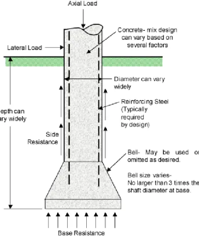
When it comes to foundation design, there are some important soil characteristics about the Broomfield area to take into account. Bentonite, a highly expansive clayey soil is prevalent throughout the Denver area. This soil expands and contracts depending on water levels and can cause unwanted settlement of the foundation, leading to extra cost. The recommended foundation design is to drill caissons or piers down to the bedrock. When the foundation is anchored in the bedrock, the soil above no longer becomes an issue because of how stable the bedrock is. Fortunate for this project, bedrock is typically shallower in mountainous regions like Broomfield, Colorado.
For more information, see the Architectural Engineering Work Package and Appendix.
P a g e | 6
Architectural Engineering Work Package
Project: Brocade Data Center
Location: 4 Brocade Parkway, Broomfield, CO
Owner: Brocade
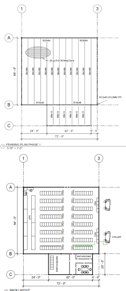
Building Description: Brocade’s second largest site, located in Broomfield, CO, is rapidly running out of infrastructure as the business grows, particularly in the data center labs. This building will primarily provide more room for data racks and secondarily provide space for engineers to work. The space should be designed to initially hold 150 racks and be scalable to house 600 racks total. The layout should maximize usable space and should be designed to have 50 engineers working within the lab. Story height is 15 feet for the one story building. The primary structure of the building is structural steel beams and columns with metal deck and open web trusses. The recommended lateral force resisting system is concrete shear walls and moment frames.
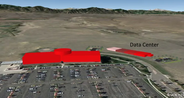
Site location: The Broomfield, CO branch of Brocade has plenty of available land, so finding space for this additional server rack lab was no problem. The initial 150 rack space was chosen to be across the street in the north direction from the existing structure so that the parking lot can be shared and the engineers can easily walk over to the rack lab. The expansion of the building will occur along the main road into the property in the west direction so that all points of the rack lab are equally accessible from the existing structure. There is plenty of space for additional parking on either end of the fully scaled rack lab. Several options were considered in the site selection process. Option 3 was eliminated because of its lack of accessibility from the current parking lot and existing structure. The recommended location is a mix of Option 1 and 2 for its ease of accessibility from the parking lot and existing building. The site selection research can be seen in the Appendix.
Figure 1: Site location in Broomfield, CO
P a g e | 7
Structural Design
Building Code: 2012 International Building Code
References: Loads: ASCE 7-10
Steel: AISC 360-10
Concrete: ACI 318-05
Weights:
Slab on Grade Live Load = 250 psf (rack weight)
Dead Load = Slab self-weight
Roof Live Load = 20 psf
Snow Load = 20 psf
Material Selection: The recommended material selection is structural steel. The reasons for selection steel as opposed to concrete or timber/masonry are that steel minimizes area occupied by the columns which maximized the floor plan for rack space. Steel is easy to install and uninstall which allows for changes in the building over time. This building will undergo four phases over twelve years (one phase every 3 years). Steel construction also has minimal on-site erection time and construction time. These are important characteristics for a phased
construction. By nature, data center floor plans are repetitive and simple. A more complicated framing layout might call for timber or concrete as the structural material.
Practical Span Ranges: Steel beams can span anywhere from 10 to 75 feet and are typically spanned 30 feet. Open-Web Joists typically span 60 feet and metal decking can span anywhere from 10 to 20 feet.
P a g e | 8
Exterior Architectural Materials
A radiant barrier on the underside of the roof will allow for the exterior materials to use methods of natural cooling (Figure 2). The primary source of heat build-up is sunlight absorbed through the roof, walls and windows. A radiant barrier (Figure 3) can reduce heat gains on the roof by 25% and will also double as insulation for this project. Dark colored exterior materials absorb 70-90% of the radiant energy from the sun while light colored surfaces effectively reflect most of the heat away. The recommended exterior architectural material for the rack lab is a light colored surface with radiant barriers as the primary insulation.
Rack Layout: The rack layout will include 9-10 racks per row. Racks are typically laid out with 8-12 per row. The more racks that are next to each other without interruption, the more efficient the system is. For example, a row length of 1 rack would be the least efficient, while a row length of infinite racks would be the most efficient. Having more than 12 racks per row is not feasible due to means of egress and fire codes. For reference, see the phase 1 rack layout in Figure 4.
Framing Options: The chosen framing option was to run the joists in the long direction and the beams in the short direction. This layout was chosen in order to eliminate the need for columns in the server room. The 6-foot on center joist layout was chosen based on optimizing the metal deck span. For more information, see the structural calculations in the Appendix.
P a g e | 9
P a g e | 10
Phase Construction: This building will be built initially to hold 152 server racks and will be scalable to house 608 racks. This growth will be done through a 4-phase process, adding 4600
ft2 of space (room for 152 racks) every 3 years. This process is recommended to eliminate
wasted space. If the entire 20,000 ft2 were built up front and only a portion of that used, there
would be an unnecessary cost to maintain the unused portion. The phased construction will minimally interfere with operations in the data center by simply adding on to the building and opening a doorway when the addition is complete.
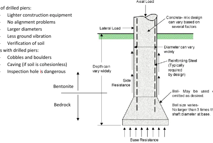
Foundations: The foundation design for this project will need to account for expansive soil. Bentonite, a highly expansive soil, expands when saturated with water and shrinks during drought periods, causing settlement of the foundation. One way to avoid this is to drill caissons (or piers) into the bedrock (Figure 5), which will not settle. Bedrock depths can range from 10 feet to 150 feet below the ground surface but are typically shallower in mountainous or high elevation areas such as Broomfield, CO. The Broomfield Building Department also stated that drilled piers to the bedrock are a
common foundation design for the area.
The benefits of drilled piers are that they don’t have alignment
problems and the larger diameters allow them to support more load. Drilled piers also require lighter construction equipment than other foundation systems and therefore, less vibration during installment. When drilling the hole for the pier, the soil type can be verified to check the accuracy of the soil report. Some problems with drilled piers are that there is the possibility of running into large cobbles or boulders which require much effort to move. If the soil is cohesionless, there is the possibility of caving. Also, inspection of the hole can be dangerous.
P a g e | 11
Conclusion
On Tuesday, March 5th, 2013, Brocade representatives travelled to Cal Poly for the
preliminary presentations. From these presentations, the top teams would be selected to
present again at Brocade’s headquarters in San Jose, CA on Friday, March 8th, 2013. My group
was asked to present again in San Jose, along with 2 other groups. Only one group was not asked to present again. The day in San Jose was spent presenting in the morning, followed by networking with Brocade employees in the afternoon and a tour of the facilities. Later in April, Brocade came down to San Luis Obispo one final time to host a reception dinner for all teams involved and announce the winning teams. The reception was held at Novo on Higuera Street. The night began with catching up with our teammates and then talking with the Brocade
representatives. After a five course meal, the winners were announced. Our team was awarded second place. Initially, there was disappointment among our team, but we were all happy with the experience and grateful to be walking away with our $400 per person prize money.
I would definitely do this project again and would recommend it for other ARCE’s to get involved in. That being said, because the project changes yearly, it is important to make sure there is an opportunity for a structural element of the project before committing to do it. The Brocade Challenge gave me exposure to an experience that I would not have found in any other class at Cal Poly.
balanced
~design
SHEET NO _ __ _ _ _ . , - - -CALCULATED BY _ __ _ _ _,_,.ATE _ _ _ CHECKEDBY _ __ _ _ _ O,ATE _ _ _ SCAlF :~e.r5
+-e-e.l
Dt~'-k
OC.J'11.Y~
...,C.4i'
X .3~1 b-~vs J~c.k -o«ra)lt{h
~01 nJ.-t. - -1--- - - I_!_"'----+-
1 - t
r I·
'DL
~
z.A.'lf:s .f
\(
.\
L-: fL.;-~» ~
r
~'!)
LL=
~0 f'S..fI
I I~
tl>e-<
~
S»a
_
..,
'~JJ+t-~--,--1
-!-r-1 _._
,
.--'1'----;---; -:
~t-tlr
·
.
hoi"~
: I l) 1J,.<AJ.I~
j
1::oA'"'S ( '\ ' O..l.. -z.)L
~w'-'~,
i
~
)
ij? ~ ~
1.11e~<h
1 1'3) 1...
4'cp\e
C
fd
I -tALJ..)~
clfi'"'•"U.S.- ' -- -
--
1
-~----
j I - · - .. - - .Opr
\~
ns:
20je>..?4-~-'31o
l
sops€
tl!( Cht.C.p'f.Y'v
·
.E..il-
{
0 ( Ai'At)o£.::,_z.v
~ ~
'f'J
i
f\ -..
+
,- "
~s-f
:
i'h"
l)~
~
,_
_,~ ~
B...
'
I 1h"
dL-r
~
lt7;h+
d.L..UL
-
-1
\A-1;-\-~
'?r:Wlt.tff'"';--..t-
(
J
~
l\
,~ ~ -h, f
·
~
-f1_
rbo
V
~ '"-L (1e
r f"(. · t - - - - · - ·I
~t
' ' Ibalanced
~design
Vul
(r:~.ft {i~LI\/DjI
I
Llc..
fsl
~s
f
~
1.1' ) "1
o
~
p
(
.f
I JO•~--- ---SHEET NO _ _ _ _ ~·- ---CALCULATED BY _ _ _ _ _ _ _ _ _ D A T E ' -CHECKED BY _ _ _ _ __ _!JAT.,___ _ _ SCALE ' Idocument. pdf http://www.vulcraft.com/products/catalogs/steeljoists/document.pdf
L R F D
S IANUAI{[) LOAD I Atilt ~OillONGSPI\N Sl tl:l. JOISI S, LH.StNltS
Based on u ~ ksi Maximum Yield Strength -lond.s Shown In Pounds Per Uuoor Foot (pll)
Jotst Approx WI Depth Max SAFElOAD·
Destgnation in Lbs Per lo Load in Lbs SPAN IN FEET
Linear Ft in<!>•• (pit) Bel ween
tJolsiS oni:J) < 29 29·33 34 35 36 l1 38 30 •o ~1
·~ ol
•
•
•s ~8 47 48 24LH03 11 24 601 17<3ll 513 505 I 504 484 450 439 416 400 ~~ I ~; 351 336 322 310 295 ::'JS 226 z,a 204 1GB 175 11!2 152 12A 116 109 102 96 "24LH04 12 24 737 2f360 628 >97 5GB 540 514 490 ~68 U7 427 409 '"393 376 361I
346 333-~as >65 L.C6 '127 210 19S 162 1G9 IS$ ·~a 13{\ 130 124 114 1Q7 24L1'105 13 24 789 228!10 673 669 660 628 59ll 570 5« 520 496 I 475 456 436 420 403 387 :';06 2._'.jl 28~ ::!f-4 2.ol4 226 210 195 182 171 150 150 H1 132 121 24LH06 16 24 1061 ~80 906 1168 832 795 756 720 685 655 625 398 571 546 -srr SOf 480 411 382 356 331 306 284 ?63 245 22-~ 211 197 184 172 161 152 24LH07 1T 24 1166 33810 997 957 919 882 847 811 774 736 ;~~ t ~~~ 639 610 583 559 535 4~~ 421 3U3 :'!67 343 320 2ll7 275 2:23 206 195 162 171 24LH08 18 24 1243 30<JOO 1060 1015 973 933 895 858 817 780 745 712 682 652 625 600 576
4E:J 447 ••s JSE 352 138 314 292 2.72 :25-l 238 222 208 1?6 1e4
:?4LH09 21 24 14&< 42450 1248 1212 1177 1146 1096 10~· 994 948 903 861 822 7e6 751 720 690
%.? ~JO 501 .s~.o 42.1 393 ~53 JJI 311 :.'9:! 2"12 2~4 ~Ja 2('3 ]00 24LH10 23 24 15<7 4485Q 1323 1284 t248 1213 1182 1152 1105 1053 1002 955 912 873 634 799 7b8
~96 5.':.!1 !·18 $0/l 474 4:19 400 JJA :.s• 3?6 3~U 2AS 266 249 234
24LH11 25 24 1630 4n80 IJ90 1350 1312 f276 1143 12TO nao 1152 1101 1051 1006 963 924 885 650 624 .saf! 555 5~5 <ss 47~ Wl 4t6 :!1!8 361 3J7 3-1S. 294 276 259 < 34 34-41 42 43 44 45 46 47 I 48 49 so 51 I ~~ Sl 54 65 56 28LH1l5 13 28 62"3 21HIO 505 4e4 465 445 429 412 397 382 367 355 342 330 319 309 298 719 205 192 180 169 159 150 142 133 126 11~ 113 107 102 ll7 28Lf!06 16 28 ~2B 28140 672 643
I
618 592 5611 546 525 5115 486 469 451 436 421 406 393 28~ 270 253 2"3 223 209 197 186 175 168 156 148 140 133 125 2BL1'107 17 28 934 ,1770 757 726I
696 667 640 815 591 508 5<7 528 508 490 474 457 442'P6 ::os .:es 267 ~~1 236 222 20"3 1!:17 166 176 1G6 158 ISO Hl
26LH08 18 26 1001 34020 BfO 775 744 712 684 657 630 604 580 556 535 516 498 .f78 462 348 3~.5 305 2% 258 252 236 2.22 209 195 18> 175 165 156 148 2BLH09 21 28 1232 41660 1000 958 918 879 844 810 776 748 721 694 669 645 622 601 580 428 400 375 351 32.Q 309 2!11 274 :!58 243 22e 216 204 193 183 28LH10 23 28 1347 ~810 1093 1056 1018 976 937 900 864 631 799 769 742 715 690 666 643 4G!) 43~ 41' 1fB J.64 342 J22 :!{)3 2B!i ~fi9 255 241 226 215 204 26LH11 25 28 1445 49140 1170
I
1143 1104 1066 1023 982 943 907 873 641 810 781 753 727 702 49~ .t.l~ 4·1·~ 4;'.3 397 373 35\ 331 312 204 276 263 .249 236 2~3 2BLH12 27 28 1587 53970 12es 1255 1227 1200 1m 1149 1105 1063 1023 984I
948 913 a eo 649 819 ~.4~ s:o 496 476 454 435 408 m 361 3JO 32t )(p 285 270 756 26tHt3 30 28 16S. 56250 1342 1311 1281 1252 1224 1198 1173 1149 1126 1083 1041 1002 964I
930 897 56~ S·D SlB ·1~5 47:2 452 .03 415 ~~ :37J ~2 2J2 314 297 2f!1 < 39 lV.~S lt7-4PJ so 51 52 53 Sol 56 56 57 so 59 60 81 I 61 63 64 32LHOG 14 32 647 25230 25230 507 489 472 456 441 A26 412 399 385 373 .:l8l- ~~ ~Q ~ 321 211 109 189 179 169 1GI 153 145 tJS t31 U$ Jl!l',.
'tl)ol 32LH07 16 32 728 263M <o3BO 568 5<9 529 511 493 of/7 45:? 4.f1 432 I 410 ~D!r '3~ lleJ 370"""
23-5 223 ::!11 200 189 17!l j71! 162 154 146 140 1J3 IV 121 113 32LH08 f7 32 790 30610 308!0 6t6 595 574 553 535 517 499 4e3 - ! 453 ·~~ ~!: ~Ill.g
3.88 255 242 2Z9 716 205 t94 184 175 167 159 137 l2S 32LH09 21 32 992 38670 38670 774 747 720 694 670 648 627 606 586 568 sso5,.
St7 S02 w '-19 :Mil .:R~. 270 :'56 243 :130 Zl9 208 Hi8 18~ '~ m <64 151 32LH10 21 32 1096 42750 4uSO 556 825 i 798 768 742 717 693 867 645 624 803 $p:_
p~ ~29 352 132 315 2!:7 ::"8? 267 :'54 2~0 .228 217 2(11. Ito 118 111(1 32LH11 24 32 1201 46B30 458'30 937 g(iJ 870 840 811 783 757 732 709 687 ss. '1>13 f26 ~ 51538.; 363 343 .)~~ Jn.o ).'J) 277 263 ~51 239 ~1 ~Ill 1llll !!Ill Ill/
3:2LH12 27 32 1409 54960 54960 not Hilla 1032 996 !i6t 928 897 667 B38 Btl 186 162
~~ ~~ ~ fnl~ .!SD 42.7:; t 400 334 364 345 321 31 J 2f!S 261 ?fi7 ~·~ 32LH13 30 32 1572. 61320 1225
1
~~
11$ 11iS 1072 tOM 999 !.164 931 900 871 SH &ttl l'SD -f:g~ 400 48-1 4U ~;111 3!)7 31G l-'4 ~1ti 319 _:lQol_ 288 215 ~ 249 32LH14 33 32 1618 63120 6Jt:l0- 1264 1239 1215 --;';~2 t'170 114S 1107 11)&9 1032 997 9&4- ~} 903 874 ~ ~15 .;gs '76 4~-'3••o
H7 3~ 174 l-'<5 337 321 ~ 116 ;'il.C 32LH 15 35 32 1673 65250 65250 1305 1279 : 1255 1231 1207 '1186 1164 1144 1125 ! 1087 1051 !017 i84 952 924 532 Sl 1 I 492 473 4.54 <33 42:! <PI 39.3 l ';74. 355 338 322. 300 2ll2 • <J .l .. B A7-~& H 58,.
60 616'
6l fi4 65 65 67 68 69 I '10 t 71 12 36lrl07 16 ~ 590 25350 25350 438 424 411 399 387 376 36$ 355 345 I 336 327 31$ 310 lOt':
177 168 160 15-3 14& 140 134 tl8 m 117 112 107 103 ~ 35LH0B 18 l6 649 27900 27900 451 ~ l ~~~ 439 •215 ~14 4Dl J90 37!1I
3G9' "3SG'~=-
3~0 331 322 I 194 tea 160 153 146 140 134 128 12.3 113 lll'l 104 ~"
36 832 35700 35760 616 597 579 501 544 528 I~ 499 .(84 .f71 459 «S 433' 423 412 I 247 2:JS 2:2~ 214 204 1~5 1T9 171.
163 1-57 150.'"
138 13J 36LH10 21 36 915 39390 J93~)0 681 660 639 619 601 583 567 550 535 520 5UT ~~ <(80 ~66' 454 :27l 2EO 248 236 225 215 206 197 188 t6Q 173. 59 152 146 36LH11 23 36 1000 42990 42990 742 720 697 676 657 637 618 601 583 567 552 537 522 SOB 495 1197 .:-~7 z.',J 2R~ 2~7 .246 234 ~ 214 205 196 18!1 1W 173 16!; 159 36LH12 25 36 51450 S'i<sO 8B9 B62 635 810 784 782 139 717 695l
675 655 636 618 GO\) SS3 'lC:J )'i' 322 .30? ...292 273 2!i7 2$5 243 232 222 213 204 195 187 '-6LH13 30 l~ t~u7 605"10 5()510 104:. 101:~' ~~ 951 922 894 868 843 019 ' 7D6 774 753 732 7f2 694 .J ~ :", j~~ ~78 359 342 .l27 3t2 198 1~5 ~73 262 ~SI :!40 231 2:!2 36LH1-I 36 :.>& l&!il 66690 66690 1152 1132 1093 1059 1024 991 981 931 903 I 876 a-so 826 802 780 7574:.:; ..;34 I -112 3'i2 373 356 :U9 i l l l09 ; :295 283 270 :l59 241 2:17
J6LH15 36 3G 16JS 70320 70320 12f3 1f92 1f11 1153 tne 1081 1047 1015 984 955 927 900 874 BSO 826
-~ t:.:l ~1::·1 448 4~4 413 .;.g .. 37$ ~~a 3<2 327 .)12 299 :!BG 274 26l
107
balanced
~design
,.__,.______ f:p,-_l JO'~--- ---SHEETI'jO· _ _ __ _ OF· -CALCULATED BY _ _ _ _ _ _ _ ______J)ATc_ _ _ CHECKEDBY _ _ _ _ _ _ IDATE _ _ _ _ ro""'
1.\l'(z.e
tJ.~
~---1~· It- 1'1 L.vd
I1
I
D
./o
l DJ
'=I
'L .~D
S
;
n
w
l
b".J
I
i II
~·~~ <.3
-2.3
Aut,
11 .
1-\,;;1 \ •"~
: \.(3
4-)
~
\
lJL (u~)
•
12.
.~
s
f.
I 1z
.?,x
tAl:.
4LW~"
.11+
Vy-
:.
~
=
~1
K
I
'
·~~-=- ~-:./
$'"
1"(·~, 1-;?,I
l
I
1-JO
balanced
SHEET NO~d~sign
CALCULATED BY CHECKED BY S<:A (.hq:1-l
~v~
(l"+) ('l't· ~~pq
-
I
~v
W<:i h 1\ + - - - - , ,V,I_w
'VI->:be.
\:.\ 21X83 I ~3()1--tvf~~
·
2.Jf JrlI
~-~,l
t
' u~t
f
or
e~ekt"
n I'b
...,..,
...., (
jj
1
\~X~ ~
~ii~·JI-yrjr~'~""'
I
I
I I ~-
i
t
,__1_ ' II
~ + I I II
I
Ibalanced
~design
"1"2...!(> 1 ~~- l( " -4-Vv..-r
:
-17 11 < )(., '-l..f.·B--!-t-1 .Jo,_· - - - -SHEETNO _ _ _ _ _JJ; - - -CALCULATED BV _ _ _ _ _ D A T " -CHECKEDBY _ _ __ _ _ DATc_ _ _ 1 II bb.
G. I c;' ( \"11. t:>l(~.,f)
1
(
10)11..\4 344l
~Jo
db
r.
"f )
l
u)
' I.
Ibalanced
~design
_(+IS (5'ee (
~rn--11!1aJ.I<-+-
1
A*=-:. 3b I l(3Z.
'
\
15"2-f
{'z,J1
pS
DL
ZO
pS
f. .fnt> W I I1.-z.
o
L
(.IL "1:12.
~
p5-f I 1I
I1---'-~
li
v~
kV\~ :-
s+
I
I
\'\-:.. ~ • 0 SHEETI'/0 _ _ _ _ -J.> -CALCULATEDBV _ _ _ _ _ D A T t _ _ _ CHECKEDBV _ _ _ _ _ DATE _ _ _ SCAL - - -- --'--'--1 L{}-C M;Vlbj
lZ-
..(,
al~n1-s. II
It
S
I~~
L
ocA ·T
lb
N
?--
E:.s
Eft~c
H
/
prev~·,
I
~nq
·JJ·"J
r-=\
~v-,\
A·Vlj
-\oot?r
·
,
f'\T
?'fDpMty
\'1'1\~1 3 A B C 36LH 09 36LH 09 36LH 09 36LH 09 36LH 09 36LH 09 36LH 09 36LH 09 36LH 09 36LH 09 36LH 09 20 g a PL B-36 M e ta l D e ck W2 4x 84 W2 4x 84 W1 8x 48 W1 8x 48 W8x13 W8x13 W8x13 W8x13 W8x13 W8x13 64' 0" 72' - 0" 24' - 0" 42' - 0" 6' - 0" W1 2x 40 C O LU M N T Y P . 6' - 0" TY P . Sc al e Pr oj ec t n um be r Da te Dr aw n by Ch ec ke d b y 1 /1 6 " = 1 '-0 " 3/5/ 201 3 4: 39:2 6 PM
S.1
RO O F F R A M IN G P LA N 03 13 01DATA
CENTER
03. 05 .1 3 C. M O R E H A R D T TE A M 6 1 /1 6" = 1 '-0 " 1 FR A M IN G P LA N P H A S E 1 No . De sc ri p ti o n Da te1
3
A B C
PDU PDU PDU PDU PDU PDU PDU PDU
CH
IL
LE
R
CDU CDU
PDU PDU PDU PDU PDU PDU PDU PDU
SWIT CH GE AR S UPS 64' 0" 42' - 0" 20' 0" 6' - 0" 24' - 0" 72' - 0" BAT HROOM S 8' - 0" 4' - 0" Sc al e Pr oj ec t n um be r Da te Dr aw n by Ch ec ke d b y 1 /1 6 " = 1 '-0 " 3/5/ 201 3 4: 39:2 6 PM
S.2
RACK LAYOUT 03 13 01DATA
CENTER
03. 05 .1 3 C. M or eh ar dt Te am 6 1 /1 6" = 1 '-0 " 1 RA C K LAY O UT No . De sc ri p ti o n Da teSc al e Pr oj ec t n um be r Da te Dr aw n by Ch ec ke d b y 3/5/ 201 3 4: 39:2 7 PM
S.3
RA C K L A Y O U T 3 D 03 13 01DATA
CENTER
03. 05 .1 3 C. M or eh ar dt Te am 6 1 RA C K LAY O UT No . De sc ri p ti o n Da teSc al e Pr oj ec t n um be r Da te Dr aw n by Ch ec ke d b y 3/5/ 201 3 4: 39:2 9 PM
S.4
ST R U C T UR A L 3D V IE W 03 13 01DATA
CENTER
03. 05 .1 3 C. M or eh ar dt Te am 6 1 ST R U C T U R A L 3D V IE W No . De sc ri p ti o n Da teWeek Hours
1
5
2
6
3
6
4
6
5
15
6
15
7
20
8
20
Total
93
Time Sheet
Team 6
Chandler Morehardt
Alexa Coburn
Kerry Sun
Juan Silva
Greg Wang
Raul Chagoya
JD Torres
Client:
Project Name: Brocade Cal Poly Challenge 2013
03.05.2013
P a g e | 2 Table of Contents Report….………..………3 Division of Responsibilities Overview of Design Financial Analysis Recommendation Lessons Learned Work Packages Architectural/Structural………8 Mechanical….………..………13 Electrical….………..……….18 Appendix
Discounted Cash Flow Model Structural Calculations Structural Drawings/Plans Map of Brocade Property
Mechanical/Piping Single Line Drawings Mechanical Calculations
P a g e | 3
Problem Statement
Brocade’s second largest site is located in Broomfield, CO. The site is rapidly running out of infrastructure as business grows, particularly in the data center type labs where Brocade develops and tests it products. The goal of this project is to help Brocade decide the best way and what technologies to use in the infrastructure for a new building.
Plan and design a new building to support Brocade R&D and product testing rack labs. This space should use innovative ideas to both lower initial construction costs and operating costs while being highly efficient or best in class Power Utilization Effectiveness (PUE). The building needs to be designed with scalability and flexibility allowing for racks to be added, growth of density in the racks, as well as designed to allow for redundancy to be incorporated or added through its life. The building must also be financially feasible, taking into consideration all associated costs.
Division of Responsibilities
Architectural/Structural Engineering Work Package: Chandler Morehardt Mechanical Work Package: Alexa Coburn, Juan Silva, Kerry Sun
Electrical Work Package: Greg Wang, Raul Chagoya Financial Package: JD Torres
Overview of Design
The building will be a structural steel frame building with space for 152 racks per
phase. This 4-phase construction process will occur over a 9 year period and be able to hold 608 racks by completion. Our cooling system consists of three main components: a rear-door heat exchanger, coolant distribution unit (CDU), and an air-cooled chiller. The rear-door heat exchanger attaches to the back of each individual rack and neutralizes the heat directly at the source,
maximizing energy efficiency. The second essential component of our design is the CDU unit, which consists of a heat exchanger, pumps, controls, and a piping distribution manifold. The third
component of our design is an air-cooled chiller that is located outside and utilizes Broomfield’s cold weather to incorporate free-cooling into our system. In our data center design, we decided to use overhead flexible piping rather than the traditional under-floor hard piping. Additionally, we will have two cooling accessories: a negative pressure ventilation fan to remove excess heat from the data center and one AC unit located in the meeting room. The electrical distribution will be accomplished through a 480 to 208 V AC system, versus other AC or DC-DC distributions. The electrical system will mainly be powered by utility, however in the event of a power failure, backup diesel generators will supply the required power. All of our electrical components are running off a dual-branch design, providing N+1, and for our case, also 2N redundancy. Having 2N redundancy means that maintenance can be provided without shutting down any critical loads. In our design we utilize uninterruptible power supplies (UPS), load banks, power distribution units (PDU), and
P a g e | 4
system great flexibility. All these components work in unison to accommodate the needs of powering and monitoring this data center.
FInancial Analysis
The estimated capital cost of constructing the data center with all of its components is $4,028,411. Under favorable circumstances, Brocade could build the data center and profit $500,000 from the sale of the building within the first year of the project. The money earned through this scenario has more value than the money that would be profited from selling the building after a ten year build to own scenario.
When looking at our project versus conventional data center designs, we have found that ours is more efficient and therefore economical. Although the capital cost of our data center is slightly larger per square foot than typical data centers, the savings in operational costs is a benefit that makes the higher capital cost negligible.
Three scenarios were run (see appendix for Discounted Cash Flow Models): build to suit, build to own and build and lease back. Based on the numbers run through our discounted cash flow model, our recommendation is for Brocade to pursue the Build and Lease Back financial model.
Under a build to own scenario, even if the building’s value went up 5% per year, its NPV would be worth less than 4 times the amount it took to construct the building even after taking account the increased value of the building after Phase 4 of construction. Even after escalating the building value 5% per year, the discounted cash flow model shows that the building would be worth $1,971,000, which is significantly smaller than the $4,031,000 it will take to initially construct and run the building.
Build and Lease Back shows similar operating cost to Build to Suit. The difference will obviously be the initial capital gains. Project revenue from these two scenarios will come from the sale of the land and/or building. Our finance model shows that it will be much more financially viable to construct and subsequently sell the building under the Build and Lease Back scenario. A Build and Lease Back scenario would be ideal because of the initial revenue in year zero it provides while allowing for an exit strategy that simply involves ending the 10-year lease and selling off assets.
P a g e | 5
Recommendation Structural:
One of the main structural concerns is to maximize the floor space for rack layout. The chosen structural material is steel because of how long steel can span without needing
columns. The chosen joist system of open-web trusses typically span 60 feet. Concrete and timber buildings require more supports throughout the framing plan and take more construction
time. Although steel can be slightly more expensive, it minimizes the area occupied by columns, allows for changes in the building over time and minimizes on-site erection time.
Another important requirement for the architectural design of this building is to prevent the racks from overheating. From a structural standpoint, this means choosing an exterior material that minimally absorbs the suns heat. Dark colored materials absorb 70-90% of the radiant energy from the sun. A solution to this is to use a lighter colored exterior material as well as radiant barrier insulation. Radiant barriers can reduce heat gains on the roof/walls of the building by 25% and can also double as insulation.
When it comes to foundation design, there are some important soil characteristics about the Broomfield area to take into account. Bentonite, a highly expansive clayey soil is prevalent throughout the Denver area. This soil expands and contracts depending on water levels and can cause unwanted settlement of the foundation, leading to extra cost. The recommended foundation design is to drill caissons or piers down to the bedrock. When the foundation is anchored in the bedrock, the soil above no longer becomes an issue because of how stable the bedrock
is. Fortunate for this project, bedrock is typically shallower in mountainous regions like Broomfield, Colorado.
For more information, see the Architectural Engineering Work Package and Appendix. Mechanical:
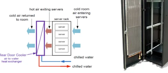
Our cooling system consists of three main components: a Rear Door Heat Exchanger (RDHx) that attaches onto the back of each rack, a Coolant Distribution Unit (CDU), and an air-cooled chiller. The RDHx is a passive liquid-cooled heat exchanger that attaches directly to the back of each rack. By close-coupling the heat exchanger to the heat source, a “mini” hot aisle is confined in the space between the servers and the rear door, providing an ultimate containment solution. By using RDHx’s, a hot-cold aisle arrangement of racks is no longer necessary; the air entering the front of the rack has the same temperature as the air exiting through the back door. As opposed to typical CRAH cooling systems, which require fans to move the air from the heat source to the cooling unit, RDHx’s do not use fans since they neutralize the hot air directly at the heat source.
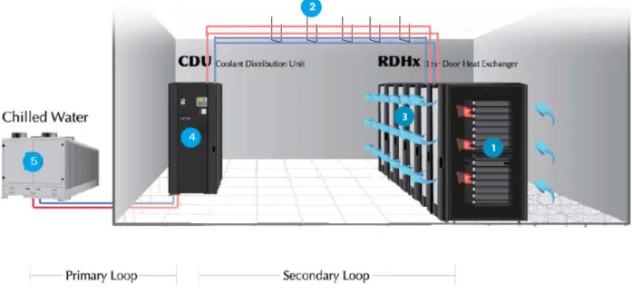
The CDU unit is composed of a heat exchanger, pumps, controls, and a piping distribution manifold. The CDU distributes cooled water to the RDHx’s, creating an isolated secondary loop separate from the primary chilled water system loop, which enables precise control of the water supply and pressure. Heat removed by the RDHx’s is then returned to the chilled water supply by means of the heat exchanger in the CDU. Additionally, our system addresses redundancy by incorporating redundant pumps, actuators, and valves in case the initial components fail.
The third component in our design is the air-cooled chiller. We chose to use an air-cooled chiller rather than a water-cooled chiller for several reasons. First, water-cooled chillers require a
P a g e | 6
mechanical room and a cooling tower (which would raise capital cost) while air-cooled chillers utilize free, open space outside, which we have plenty of. Secondly, since the temperature of Broomfield, CO is generally cold, using an air-cooled chiller is a great way to take advantage of cold air as free cooling resource and implement free-cooling into our design.
The piping we decided to go with is overhead, flexible piping. This flexible piping eliminates the use of intermediate fittings, which reduces the potential for water leakage and raises the reliability of the pipes.
Lastly, we included negative pressure ventilation fans to help extract additional heat in the data center. Although our primary cooling system composed of the RDHx, CDU, and chiller will neutralize the heat produced by the server equipment, we want to include extra fans to extract any extra heat produced. Additionally, we are including an AC wall-mount unit in the meeting room to cool the engineers while they work.
Electrical:
For our electrical distribution we chose the traditional 480 V to 208 V system. However, our other ideas included DC-DC and running higher AC voltages. The problem with the conceptual idea of running 380 V DC to the racks, which provides the highest efficiency over any system, is the lack of compatibility. In order for server racks to handle 380 V there would need to be a new generation of IT and power equipment. IT vendors would only proceed with this revolutionary change if there’s a compelling economic advantage for their customers, which there isn’t really at the moment. The main problem with running higher AC voltages as they do everywhere else in the world besides North America is the higher potential for fault currents. Without a primary transformer in this distribution, the fault current levels are dangerously high around all the electrical components. This creates a major safety hazard for a data center environment such as Brocade’s, where there will constantly be engineers working on powered equipment. Higher potential for fault currents also raises the Personal Protection Equipment level, which makes it more difficult to operate and make changes to equipment.
The standard 480 V to 208 V best suits our application. Schneider Electric’s new product line of UPSs and PDUs offer efficiencies closely comparable to DC systems, monitoring at all levels, scalability options, and easy installation and maintenance. The actual voltage distribution from the utility to the server racks follows a dual-branch layout, ensuring N+1 redundancy which also turns out to be 2N. Our main power sources are backed up by diesel generators. This design is outlined in our single-line drawing attached in the electrical work package.
P a g e | 7 Lessons Learned
We learned a lot of lessons in professionalism and communication during this project and are all better students because of it. A major factor of our teams success is that we held group meetings early and often. We met 3 times a week to share ideas with each other and discuss different angles for the solution. One challenge of being in an interdisciplinary team was that we had to work on how we each translate what we know about our specialty into a language that another team member can understand.
Another key lesson learned was that it is important to have open communication with the Brocade representatives, Nathan and Victor. Going to office hours was always beneficial and helped steer our group in the right direction after each meeting. The fact that Brocade made themselves available through conference calls and email correspondence was largely important to the progress of our groups work.
P a g e | 8
Architectural Engineering Work Package Chandler Morehardt
Project: Brocade Data Center
Location: 4 Brocade Parkway, Broomfield, CO
Owner: Brocade
Building Description: Brocade’s second largest site, located in Broomfield, CO, is rapidly running out of
infrastructure as the business grows, particularly in the data center labs. This building will primarily provide more room for data racks and secondarily provide space for engineers to work. The space should be designed to initially hold 150 racks and be scalable to house 600 racks total. The layout should maximize usable space and should be designed to have 50 engineers working within the lab. Story height is 15 feet for the one story building. The primary structure of the building is structural steel with metal deck and open web trusses. The recommended lateral force resisting system is concrete shear walls and moment frames.
Site location: The Broomfield, CO branch of Brocade has plenty of land to build on, so finding space for
this additional server rack lab was no problem. The initial 150 rack space was chosen to be across the street in the north direction from the existing structure so that the parking lot can be shared and the engineers can easily walk over to the rack lab. The expansion of the building will occur along the main road into the property in the west direction so that all points of the rack lab are equally accessible from the existing structure. There is plenty of space for additional parking on either end of the fully scaled rack lab. Several options were considered in the site selection process. Option 3 was eliminated because of its lack of accessibility from the current parking lot and existing structure. The recommended location is a mix of Option 1 and 2 for its ease of accessibility from the parking lot and existing building. The site selection research can be seen in the Appendix.
Figure 1: Location on site
P a g e | 9
Building Code: 2012 International Building Code
References: Loads: ASCE 7-10
Steel: AISC 360-10
Concrete: ACI 318-05
Structural Criteria
Lateral Shear Walls and Moment Frames
Slab on Grade Live Load = 250 psf (rack weight)
Dead Load = Slab self weight
Roof Live Load = 20 psf
Snow Load = 20 psf
Material Selection: The recommended material selection is structural steel. The reasons for selection
steel as opposed to concrete or timber/masonry can be seen below. By nature, data center floor plans are repetitive and simple. A more complicated framing layout might call for timber or concrete as the structural material.
Reasons for Selecting Structural Steel
- Minimizes area occupied by columns
o This maximizes the floor plan for rack space.
- Allows for changes in the building over time
o Building will undergo 4 phases over 12 years (1 phase/3 years)
- Minimizes on-site erection time - Minimizes construction time
o Important for phase construction
Practical Span Ranges
- Steel Beams 10-75’ (typically 30’)
- Open-Web Joists 10’-150’ (typically 60’)
P a g e | 10 Exterior Architectural Materials
A radiant barrier on the underside of the roof will allow for the exterior materials to use methods of natural cooling. The primary source of heat build-up is sunlight absorbed through the roof, walls and windows. A radiant barrier can reduce heat gains on the roof by 25% and will also double as insulation for this project. Dark colored exterior materials absorb 70-90% of the radiant energy from the sun while light colored surfaces effectively reflect most of the heat away. The recommended exterior architectural material for the rack lab is a light colored surface with radiant barriers as the primary insulation.
Rack Layout: The rack layout will include 9-10 racks per row. Racks are typically layed out with 8-12 per row. The more racks that are next to each other without interruption, the more efficient the system is. For example, a row length of 1 rack would be the least efficient, while a row length of infinite racks would be the most efficient. Having more than 12 racks per row is not feasible due to means of egress and fire codes. For reference, see the phase 1 rack layout below.
Framing Options: The framing option was chosen to run the joists in the long direction and the beams in the short direction. This layout allows for there to be no columns in the server room. The 6-foot on center joist layout was chosen based on optimizing the metal deck span. For more information, see the structural calculations in the Appendix.
P a g e | 12 Phase Construction: This building will be built initially to hold 152 server racks and will be scalable to
house 608 racks. This growth will be done through a 4-phase process, adding 4600 ft2 of space (room
for 152 racks) every 3 years. This process is recommended to minimize wasted space, which would
occur from building the entire 20,000 ft2 building up front. The phase construction will minimally
interfere with operations in the data center by simply adding on to the building and opening a doorway when the addition is complete.
Underground: There are many data centers around the world that occupy abandoned bunkers or the side of mountains to form an underground data center. Some benefits to having an underground data center are added security and protection from the sun. Some underground data centers, like the one in Helsinki, uses seawater to cool the racks. However, unless there is already an underground space to occupy or a nearby mountain to dig in to, excavation costs make building underground very costly and not worth the return on investment from energy savings. I believe that there is more to be gained by building above ground in a cool climate such as Colorado because of free cooling.
Foundations: The foundation design for this project will need to take into account the hazard of expansive soil. Bentonite, a highly expansive soil, expands when saturated with water and shrinks during drought periods, causing settlement of the foundation. One way to avoid this is to drill caissons (or piers) into the bedrock, which will not settle. Bedrock depths can range from 10 feet to 150 feet below the ground surface but is typically shallower in mountainous or high elevation areas such as Broomfield, CO. The Broomfield Building Department also stated that drilled piers to the bedrock are a common foundation design for the area.
Benefits of drilled piers:
- Lighter construction equipment - No alignment problems
- Larger diameters - Less ground vibration - Verification of soil Problems with drilled piers:
- Cobbles and boulders
- Caving (if soil is cohesionless)
- Inspection hole is dangerous
Bedrock Bentonite
P a g e | 13 Mechanical Write-up
Alexa Coburn Juan Silva Kerry Sun Cooling System Description:
Our cooling system consists of three main components: a Rear Door Heat Exchanger (RDHx), a Coolant Distribution Unit (CDU), and an air-cooled chiller. The Rear Door Heat Exchanger (RDHx) is a passive liquid-cooled heat exchanger that attaches directly to the back of each rack. The RDHx uses a water-filled coil to directly neutralize the exhaust air before its reentry into the data center. The specially designed fin and tube coils in the rear door are protected by two 79% open perforated sheets, which help maintain airflow through the rack. By close-coupling the heat exchanger to the heat source, a “mini” hot aisle is confined in the space between the servers and the rear door, providing an ultimate containment solution. By using RDHx’s, a hot-cold aisle arrangement of racks is no longer necessary; the air entering the front of the rack has the same temperature as the air exiting through the back door. The function of a RDHx is demonstrated in Figure 1.
Not only do Rear-Door Heat Exchangers effectively control the ambient air temperature in the data center, they also provide a significant reduction in energy required to cool the building. As opposed to typical CRAH cooling systems, which require fans to move the air from the heat source to the cooling unit, RDHx’s do not use fans since they neutralize the hot air directly at the heat source. In addition, RDHx’s do not require any moving parts or electrical connections, further minimizing energy
consumption. The one concern we had about using RDHx’s was that engineers will be opening the rack doors often to work on the servers. In this instance, the heat exchanger will not be able to cool the air directly at the source, allowing heat to escape into the room; however, we came to the conclusion that
Figure 2. RDHx-LD Figure 1. RDHx Function
P a g e | 14 all the other racks with closed rear doors (air exiting at approximate 85 F degrees) will compensate for the couple of racks that heat is escaping from. In other words, the effect of opening a few doors at a time is minimal considering the size of the room and amount of RDHx’s. As for the specific brand, we suggest “low-density” RDHx’s supplied by Coolcentric This actual device is shown in Figure 2. The RDHx - LD (low density) supports low to medium rack densities of approximately 4-12kW. These heat
exchangers come in a top or bottom feed configuration to support underground or overhead piping. Additional information about this specific model is provided in the appendix. Note that we suggest using overhead piping to reduce cost and increase accessibility. This piping system is explained in detail in the description of pumping and piping below.
Another essential component of our cooling system is a floor-mounted Coolant Distribution Unit (CDU), which consists of a heat exchanger, pumps, controls, and a piping distribution manifold. The CDU drawing is shown in Figure 3. The CDU distributes cooled water to the RDHx’s, creating an isolated secondary loop separate from the primary chilled water system loop, which enables precise control of the water supply and pressure. Heat removed by the RDHx’s is then returned to the chilled water supply by means of the heat exchanger in the CDU. In addition, the CDU maintains the secondary loop water temperature above the dew point, preventing condensation on the RDHx coils and ensuring sensible cooling. Because the CDU is designed to provide constant flow to the RDHx’s, changes in heat load require modulating the primary valve and allowing more or less chilled water to flow to the heat exchangers. The CDU model we chose for our system is the CD6A floor-mount model also provided by Coolcentric. It is a versatile unit designed with redundant speed pumps. The CD6A is energy efficient, supporting 260 kW maximum cooling capacity while only consuming a maximum of 3.7kW of power. We will incorporate 8 CDU units in our design, located at side of the wall. Our design is scalable so that additional CDU units can be added as the building expands and more and more racks are included. Additionally, our system addresses redundancy by incorporating redundant pumps, actuators, and valves in case the initial components fail. The redundant pumps are shown in Figure 4.
P a g e | 15
The third component in our design is the air-cooled chiller. We chose to use an air-cooled chiller rather than a water-cooled chiller for several reasons. First, water-cooled chillers require a mechanical room and a cooling tower (which would raise capital cost) while air-cooled chillers utilize free, open space outside, which we have plenty of. Secondly, since the temperature of Broomfield, CO is generally cold, using an air-cooled chiller is a great way to take advantage of cold air as free cooling resource and implement free-cooling into our design. In Figure 6, which shows the annual temperature of Broomfield, you can see that there are only two months (July and August) that are relatively hot, allowing the air-cooled chiller to operate efficiently all but two months in the year. Some benefits of using an air-air-cooled chiller are that it lowers capital cost by eliminating the need for a separate mechanical room and also lowers maintenance cost with fewer components in our system.
Figure 6. Monthly Average Temperature of Broomfield, CO Figure 5. Basic Representation of our Design
P a g e | 16 We chiller we suggest is the YCIV Air-Cooled Variable Speed Screw Chiller because it uses the best of modern screw compressor design and manufacturing techniques. These also offer quieter, vibration-free operation and are well known for their robustness, simplicity, and reliability. They are designed for long periods of continuous operation, needing very little maintenance. Screw compressors can overcome high lift when speed is reduced, allowing energy savings without the possibility of surge as the compressor unloads.
Piping Description:
The traditional approach to piping distribution has been to use hard copper or carbon steel piping with welded, brazed or threaded fitting for routing and branching of piping to the racks. Since leakage is always a common concern with traditional piping, the distribution is generally located under a raised floor where channels or trenches are sometimes built under the pipe to capture water in case of any leaks or rupture. For our new industrialized data center, raised flooring is not necessary because we implement flexible piping instead of hard piping. A centralized distribution system allows for multiple connections to a main distribution header above the racks. The flexible piping is routed through the aisles from the distribution header to each rack and a drip pan is placed underneath the pipes. Figure 7 illustrates the use of flexible piping overhead. Seamless flexible piping eliminates the use of
intermediate fittings, such as elbows, decreasing the risk of water leaks and increasing the fundamental reliability of the piping itself. This methodology replaces all the intermediate joints in the data center with only two joints per supply and return line; one at the distribution header and one at the rack. A traditional hard piping system would have 10 to 20 joints per supply or return branch. This reduces the leak potential by 80-90% compared to hard piping. Additionally, the potential for condensation is reduced by not having intermediate fittings because it is difficult to provide insulation at the joints of a pipe, so with fewer joints, there is less chance for condensation. The flexible piping material we are using is a multi-layered composite tubing consisting of an aluminum tubing sandwiched between inner and outer layers of cross-linked polyethylene. This gives the piping flexibility to be routed through the data center with the rigidity to stay in place. The cross-linked polyethylene or PEX also offers excellent protection against corrosion and the smooth interior walls and chemical properties make it resistant to mineral buildup with hard or soft water eliminating the risk of pinholes. Table 1 shows the comparison between using hard and flexible piping.
P a g e | 17
Hard Piping Flexible Piping
Reliability Leak potential at every joint location Eliminating intermediate joints increases reliability
Installation Cost Higher installation cost. System balancing
requires more time adding cost to start-up balancing is less complex with the centralized Lower installation cost. System start-up and
distribution system
Amount of Joints Typical for 10-20 joints between distribution
and each rack Only 2 joints per branch
Material Cost Hard piping has lower initial cost, but overall
installation cost is higher because it takes more labor
PEX piping has a higher cost, but overall installation is lower
Earthquake/Vibration Vibrations can cause leakage at the joints Less susceptible to break or leak in earthquake
conditions
Condensation More potential for condensation due to
difficulty to insulate multiple fittings. Small cracks or spaces left without insulation may
cause condensation
Less potential for condensation due to elimination of intermediate joints between the distribution
system and the racks
Mineral Buildup Susceptible to leakage due to mineral buildup Very resistant to mineral buildup due to smooth
interior walls and chemical properties
Pressure Drop The use of elbows for turns and mineral
buildup causes additional pressure drop Smooth interior and larger radius turns without fittings reduces the pressure drop
Extra Fans and AC Units:
Since the temperature of the facility is designed to stay at 85 degrees Fahrenheit, we decided to use negative pressure ventilation fans to help extract any excess heat produced by from the engineers who work on the equipment. Our primary cooling system including the RDHx’s , CDU’s, and chiller will accomplish the task of neutralizing all the heat produced by the servers, however, we decided to add fans to make sure the data center stays cool enough to support people. We chose to use negative pressure fans over positive pressure fans due to the fact that we want more air exiting the building than entering. Additionally we are including one AC wall mount unit in the meeting room so the engineers can be in a comfortable temperature at all times.
Redundancy:
Redundancy is implemented into our cooling system to ensure system availability in the event of component failure. Our Coolant Distribution Unit (CDU) has 2 pumps internally; one of them is a
redundant pump, which backs up the CDU if the first pump breaks down. Also we have decided to have N+1 redundancy for our air-cooled chiller to prevent the failure of the chiller due to the hot temperature in July and August in Broomfleid, CO.
P a g e | 18 Electrical Work Package
Raul Chagoya Greg Wang Electrical Distribution Description:
Power distribution to data centers can be done using either AC or DC power. AC power is typically distributed at the server rack level at voltages of 120 V, 208 V, or 230 V. DC power is typically distributed at the telecommunications standard voltage of 48 V. Throughout North America a traditional 480/277 V to 208/120 V AC step-down transformation, accomplished at the power distribution unit (PDUs), is most commonly used. Everywhere else in the world uses 400/230 V AC directly to the server racks. Only a few small data centers throughout the world are currently using a DC power distribution. The different data center power distribution methods that will be discussed are shown in Figure 1, 2, and 3.
Proposals have been made recently to move towards DC distribution in order to increase overall electrical efficiency by eliminating the unnecessary voltage transformation and AC/DC conversion stage. Additionally, without the bulk of transformers a lot of floor space and floor weight is freed up. However, several studies praising the dramatic efficiency improvement from DC systems utilize historic values for AC devices that are not representative of what is currently available. For example, a recent article assumes an AC UPS efficiency value of 74-96% versus a DC UPS efficiency value of 97%. Schneider Electric’s new product line now actually offers efficiencies over 96% for their AC UPS and PDU systems.
Figure 2: Hypothetical Approach for Distributing 380V DC
With that being said, the 48 V DC distribution has proven to have worse efficiency than any existing AC system. This has led to the conceptual proposals of higher DC distribution voltages, such as 380 V DC shown above in Figure 1, to overcome the earlier problems associated with DC power. A 380 V DC approach may offer approximately a 1% advantage in efficiency over the best AC system, which can be the difference of hundreds of dollars in energy savings a year for larger data centers. However, as mentioned earlier this is a conceptual idea. A 380 V DC distribution system would require a new generation of IT and power equipment that does not yet exist. In order for IT vendors to proceed with
P a g e | 19 such a revolutionary change there needs to be a compelling economic advantage for their customers, which for most users at the moment is relatively small.
Figure 3: Common AC Distribution Outside North America
The AC system with the highest efficiency, but only by less than 1%, is the 400/230 V distribution shown in Figure 2. Virtually all IT equipment is designed for worldwide compatibility and can operate on a voltage range of 100 to 240 V. Running the server rack at the highest voltage supported requires less current given the same power capacity, one source of efficiency improvement. So hypothetically a 415/240 V AC distribution system would improve it even more. Eliminating the voltage transformations in the PDUs, originally required for the 480 to 208 V distribution as shown below in Figure 3, will remove that source of inefficiency while reducing floor weight and floor space as well. This also ends up making the component cost cheaper compared to the other AC system. However, a 400/230 V AC distribution requires running neutral conductors throughout the whole system since the 230 V output is derived from a line-neutral configuration. The extra costs required for the labor, wire, and protection devices make the overall system cost comparable to other systems.
Figure 4: Common AC Distribution in North America
A negative factor of eliminating the PDU transformer is the increased potential for fault currents. A proper application needs to be carefully implemented in order to ensure that it is safe to perform maintenance and install additional IT peripherals without de-energizing the entire system. Figure 4 on the next page outlines the concept of fault current availability for both AC systems. The arc flash potential is a major safety hazard for Brocade’s data center, where there will be several engineers constantly working on the energized server racks and PDUs. Additionally, with the higher potential for arc flash, the higher the PPE (Personal Protective Equipment) level and the more difficult it will be to operate and make changes to equipment in the data center. This is another major downside for the 400/230 V AC distribution method for Brocade’s data center, which needs to be easily scalable in the future.