DOI: 10.4236/aast.2020.51001 Jan. 6, 2020 1 Advances in Aerospace Science and Technology
and Vortex Generators
Sushil Chandra, Rajan Tyagi
*Aerospace Engineering Department, IIT Bombay, Mumbai, India
Abstract
In the past extensive research has been carried out, to study the effect of Gurney flap (GF) on symmetric and cambered airfoil for its usage in low Reynolds number regime. Use of GF at the trailing edge of the airfoil en-hances the lift due to increase in the effective camber of the airfoil, which in turn improves the aerodynamic efficiency i.e. Cl/Cd. In the present study, Eppler 423 airfoil is used to first understand the aerodynamics of such a highly cambered airfoil and later GF of various sizes were added on it to un-derstand the change in flow dynamics achieved by adding the GF and their impact on aerodynamic parameters such as Cl, Cd and Cl/Cd. Eppler 423 being a highly cambered airfoil produces high lift coefficient and smoother stall and by adding the GF of various sizes the performance of Eppler 423 improves tremendously and reason for this enhanced performance and effect of size of GF are presented in this paper. Vortex Generators (VG) generate counter ro-tating vortices that allow the flow to remain attached even at high angles of attack. Also, effect of adding VG at the leading edge of Eppler 423 aerofoil is presented in this paper. At last, results obtained from combination of VG at leading edge and GF at trailing edge on Eppler 423 aerofoil are discussed at length.
Keywords
Eppler 423 Airfoil, Gurney Flap, Vortex Generators, Aerodynamic Efficiency, Stall
1. Introduction
The Gurney flap is a small flap (like tab in aircraft wing trailing edge), added at the trailing edge of an airfoil or wing at right angle to the pressure surface. Gen-erally its height varies between 1% - 2% of chord or inside boundary layer [1]. Addition of Gurney Flap to enhance lift of an airfoil/wing is not a new concept
How to cite this paper: Chandra, S. and Tyagi, R. (2020) Study of Eppler 423 Airfoil with Gurney Flap and Vortex Generators. Advances in Aerospace Science and Tech-nology, 5, 1-19.
https://doi.org/10.4236/aast.2020.51001
Received: November 11, 2019 Accepted: January 3, 2020 Published: January 6, 2020
Copyright © 2020 by author(s) and Scientific Research Publishing Inc. This work is licensed under the Creative Commons Attribution International License (CC BY 4.0).
DOI: 10.4236/aast.2020.51001 2 Advances in Aerospace Science and Technology
to be thought of; it was erstwhile originated from racing cars, but its roots can be traced back to 1935 by E. F. Zaparka [1] patent US Patent Re19412. Its origin and usage on race car was introduced by Late Dan Gurney (1931-2018) a racing car driver, who later owned a racing car company AAR (All American Racers). He improvised the car in 1971, which was underperforming, to the winning car (as a manager post-retirement from racing), this invention was inspired from spoilers attached to the rear of bodywork to cancel lift by certain teams in the 1950s [1]. Gurney was able to use the device in racing for several years before its real purpose became known. Later, he discussed his ideas with an aerodynamic-ist and wing designer Bob Liebeck [2] of Douglas Aircraft Company. Liebeck tested the device, which he then named the “Gurney flap” and confirmed Gur-ney’s field test results using a 1.25% chord flap on a Newman symmetric airfoil. An experimental study was conducted by Bob Liebeck [2] on a Newman aero-foil. He found that the GF with only 1.25% chord length gave high-lift coefficient by increasing lift but also reducing drag at the same time. Liebeck also found that the flap height should be between 1% C and 2% C to maximize the aerody-namic benefits from this simple high-lift device. He also concluded that flaps with a height of more than h = 2% C would significantly increase the drag. Lie-beck from his results proposed the formation of two counter-rotating vortices downstream of the Gurney Flap (Figure 1). It is evident that both lift and drag coefficients increase with an increase in the height of the Gurney flap. Giguere et al.[3] conducted the study to understand the effects of the mounting location of the Gurney flap on airfoil. They found that the increment of lift coefficient had decreased when the GF has shifted forward away from the trailing edge, wea-kening the lift-enhancing effects of the flap. Also Giguere et al.[3] suggested that the size of the optimum GF for the best lift-to-drag ratio is determined by the flow condition at the trailing edge at the pressure side of the airfoil. It was rec-ommended that the flap should be submerged in the boundary layer, which was also confirmed by Li [4] through experiments. Li et al. [5] studied the effect of mounting angle of GF on aerodynamic performance of NACA0012 airfoil and found that with increase in mounting angle Cl increases as compared to clean
[image:2.595.212.540.548.692.2](a) (b)
DOI: 10.4236/aast.2020.51001 3 Advances in Aerospace Science and Technology
increase in thickness of GF, Cl is seen to decrease also zero-lift angle of attack shift is less pronounced with increasing thickness, suggesting that thicker flaps reduce the effective camber. Roy et al. [9] and Yachen Li et al. [10] found in their experiments on NACA 0011 aerofoil that addition of the Gurney flap adds camber to the aerofoil and thus increases the coefficient of lift and effect of GF on symmetrical aerofoil is much more when compared with cambered aerofoil. Also, P. Giguère et al. [11] found that addition of GF on low speed aerofoils tends to increase the effective camber of the aerofoil and thus increases the lift coeffi-cient. As evident from the existing literature both GF and VG when added inde-pendently have a positive effect on the performance of Eppler 423 aerofoil as both increases the aerodynamic efficiency of the Eppler 423 aerofoil. In the present study, firstly behavior of clean Eppler 423 aerofoil is studied than a comparison is made with configuration having GF and VG only followed by configuration having both GF and VG.
2. Materials and Methods
DOI: 10.4236/aast.2020.51001 4 Advances in Aerospace Science and Technology
(a)
[image:4.595.211.536.71.520.2](b) (c)
Figure 2. Aerofoil setup. (a) Wind tunnel schematic; (b) Setup; (c) Eppler with GF.
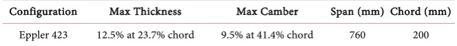
Table 1. Dimensions of Eppler 423 Aerofoil.
Configuration Max Thickness Max Camber Span (mm) Chord (mm)
Eppler 423 12.5% at 23.7% chord 9.5% at 41.4% chord 760 200
difference between the selected channel (connected to a port on airfoil) and stat-ic pressure from the Pitot-statstat-ic tube. The desired channel can be selected for measurement, and the pressure reading at the manometer is noted. Each channel of the multi-channel selector panel was numbered and marked to a pressure port on the airfoil.
[image:4.595.208.540.571.605.2]DOI: 10.4236/aast.2020.51001 5 Advances in Aerospace Science and Technology
[image:5.595.213.537.65.170.2](a) (b)
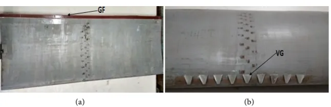
Figure 3. Aerofoil geometry with GF and VG. (a) Eppler with GF; (b) Eppler with VG.
Various configurations utilized were in % of chords, namely 2%, 3%, 4% and 5% of chord (200 mm). Fabricated models were in L shape with 5 mm base, and other dimensions are in % of chord.
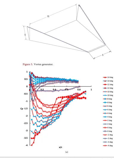
VG was used like in conventional aircraft, in which the VG’s are attached on the leading edge as shown in Figure 3(b). The patterns were chosen such that the counter-rotating vortices were formed, which will prevent flow separation and allow flow to remain attached, which is evident from the modified pressure distribution. The height, as well as dimensions facing the flow of VG, is 2.5% of chord as shown in Figure 4 and Figure 5. Total of nine VG’s were used on the airfoil leading edge, equally spaced at 2% of chord. Different configurations tested are mentioned in Table 2.
3. Results and Discussion
3.1. Variation of Coefficient of Pressure (Cp) with and without GF
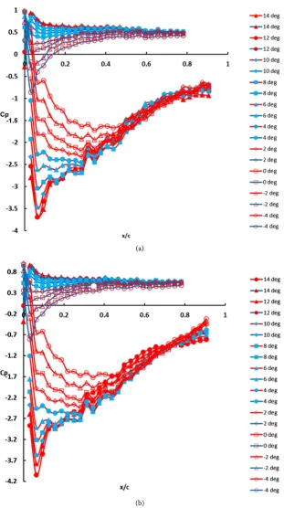
Figure 6(a) shows the distribution of pressure around a clean airfoil on the up-per and lower surface against x/c. The pressure distribution modifies as the AoA is increased, the flow separation occurs on the suction surface at 10 degrees, the peak of the suction surface goes up to −4 at 14 degrees AoA. The area keeps on increasing as the AoA is increased beyond −4, as a result, lift as well as pressure drag also increases, at around 10 degree AoA stall occurs which results in reduc-tion of lift.
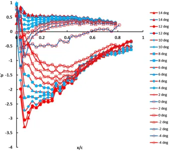
Figure 6(b) shows the modified pressure distribution over the airfoil at 2% Gurney flap. It is observed that addition of the Gurney flap alters the pressure distribution over the pressure surface that results in the enhanced lift, also addi-tion of Gurney flap results in increase in effective camber of the airfoil. However, the effect is more prominent on symmetric airfoil than on cambered airfoils. As, Eppler 423 is a highly cambered airfoil and addition of gurney flap results in further increase in camber that results in an additional increment in lift com-pared to clean airfoil, but there is a penalty in terms of reduction in stall angle.
DOI: 10.4236/aast.2020.51001 6 Advances in Aerospace Science and Technology
[image:6.595.208.538.67.184.2](a) (b)
Figure 4. Gurney flap. (a) Gurney flap dimensions; (b) Gurney flap used in experiments.
Figure 5. Vortex generator.
[image:6.595.148.532.208.744.2]DOI: 10.4236/aast.2020.51001 7 Advances in Aerospace Science and Technology
[image:7.595.208.537.67.357.2](b)
Figure 6. Pressure distribution on clean wing and with GF. (a) Pressure distribution on clean wing; (b) Pressure distribution with 2% GF.
Table 2. Configurations tested in wind tunnel.
Configuration AoA (in Degrees)
Airfoil with 2% GF −4, −2, 0, 2, 4, 6, 8, 10, 12 and 14
Airfoil with 3% GF −4, −2, 0, 2, 4, 6, 8, 10, 12 and 14
Airfoil with 4% GF −4, −2, 0, 2, 4, 6, 8, 10, 12 and 14
Airfoil with 5% GF −4, −2, 0, 2, 4, 6, 8, 10, 12 and 14
Airfoil with 2% GF and VG −4, −2, 0, 2, 4, 6, 8, 10, 12 and 14
Airfoil with 3% GF and VG −4, −2, 0, 2, 4, 6, 8, 10, 12 and 14
Airfoil with 4% GF and VG −4, −2, 0, 2, 4, 6, 8, 10, 12 and 14
Airfoil with 5% GF and VG −4, −2, 0, 2, 4, 6, 8, 10, 12 and 14
3.2. Variation of Coefficient of Pressure (Cp) with Gurney Flap (GF)
and Vortex Generators (VG)
[image:7.595.209.528.421.575.2]DOI: 10.4236/aast.2020.51001 8 Advances in Aerospace Science and Technology
is a marked improvement in the performance of the highly cambered Eppler 423 airfoil as compared to the airfoil with only GF. It can be seen that the stall angle has been increased thus delaying the stall.
(a)
DOI: 10.4236/aast.2020.51001 9 Advances in Aerospace Science and Technology
[image:9.595.211.538.73.357.2](c)
Figure 7. Pressure distribution with GF. (a) Pressure distribution with 3% GF; (b) Pres-sure distribution with 4% GF; (c) PresPres-sure distribution with 5% GF.
[image:9.595.196.538.407.711.2]DOI: 10.4236/aast.2020.51001 10 Advances in Aerospace Science and Technology
(a)
[image:10.595.215.531.67.624.2](b)
Figure 9. Pressure distribution with GF and VG. (a) Pressure distribution with 2% GF and VG; (b) Pressure distribution with 3% GF and VG.
3.3. Comparison of Variation of Coefficient of Pressure (Cp) with
and without VG
DOI: 10.4236/aast.2020.51001 11 Advances in Aerospace Science and Technology
(a)
[image:11.595.219.531.64.621.2](b)
Figure 10. Pressure distribution with GF and VG. (a) Pressure Distribution with 4% GF and VG; (b) Pressure distribution with 5% GF and VG.
DOI: 10.4236/aast.2020.51001 12 Advances in Aerospace Science and Technology
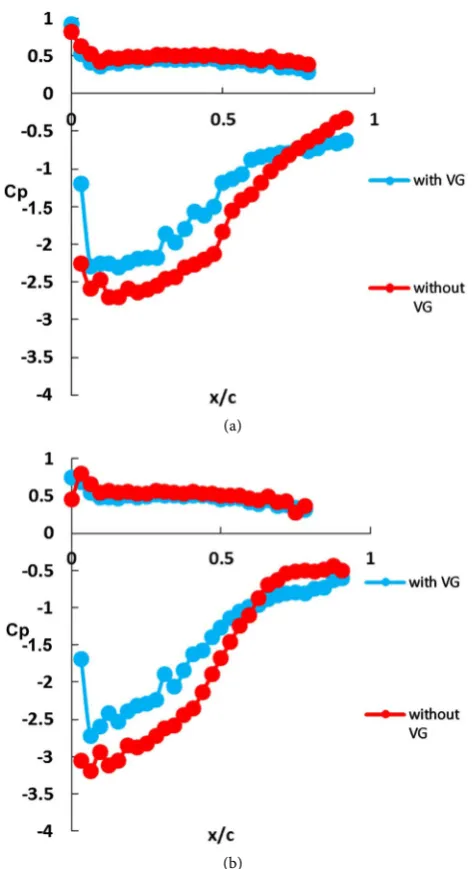
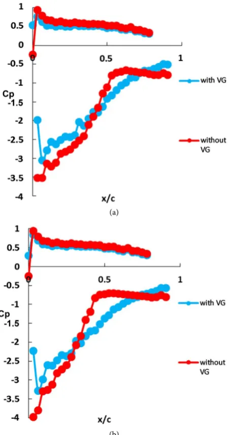
10 degree. Whereas the airfoil with VG does not show this trend, which means flow does not separate easily as counter-rotating vortices energize the flow and allows it to remain attached to the suction surface at higher angles of attack as indicated in Figure 11 and Figure 12.
3.4. Comparison of Variation of Coefficient of Pressure (Cp) with
GF and VG
When we compare pressure distribution on an airfoil with VG and GF at higher angles of attack, the pressure distribution on the pressure surface is modified, but there is a net reduction in suction peak. The overall effect is the decrease in lift, which indicates that the overall impact of both VG and GF is to increase the stall angle even though it reduces lift as shown in Figure 13 & Figure 14.
(a)
[image:12.595.256.493.258.693.2](b)
DOI: 10.4236/aast.2020.51001 13 Advances in Aerospace Science and Technology
(a)
[image:13.595.260.488.69.498.2](b)
Figure 12. Variation of Cp with and without VG. (a) Pressure distribution at α = 12 de-gree with & without VG; (b) Pressure distribution at α = 14 degree with & without VG.
DOI: 10.4236/aast.2020.51001 14 Advances in Aerospace Science and Technology
[image:14.595.152.537.71.235.2](c) (d)
Figure 13. Variation of Cp with 2% GF and VG. (a) Pressure distribution at α = 8 degrees with 2% GF & VG; (b) Pressure distribution at α = 10 degrees with 2% GF & VG; (c) Pressure distribution at α = 12 de-grees with 2% GF & VG; (d) Pressure distribution at α = 14 degrees with 2% GF & VG.
(a) (b)
(c) (d)
Figure 14. Variation of Cp with 3% GF and VG. (a) Pressure distribution at α = 8 degrees with 3% GF & VG; (b) Pressure distribution at α = 10 degrees with 3% GF & VG; (c) Pressure distribution at α = 12 degrees with 3% GF & VG; (d) Pressure distribution at α = 14 degrees with 3% GF & VG.
3.5. Variation of Coefficient of Lift (
C
l) with and without GF
[image:14.595.211.537.291.621.2]DOI: 10.4236/aast.2020.51001 15 Advances in Aerospace Science and Technology
[image:15.595.211.536.418.739.2] [image:15.595.213.534.426.555.2]3.6. Variation of Coefficient of Lift (
C
l) with GF and VG
Figure 16 shows variation of Cl with change in α for the airfoil with VG and GF, it was observed that addition of GF increases the camber and addition of VG at the leading edge reduces separation at the suction surface, and the combined ef-fect of this configuration is to increase the lift coefficient and also increase the stall angle. But in comparison with GF only configuration (Figure 15) there is a reduction in value of Cl but stall angle is enhanced with no sudden loss of lift. Thus, it can be said that addition of VG on airfoil with GF will reduce the lift but increase the stall angle as shown in Figure 16.
3.7. Variation of Coefficient of Drag (
C
d) with and without GF
[image:15.595.214.536.583.730.2]The addition of GF theoretically should increase the drag, but it is quite evident from Figure 17 that airfoil with GF produces lesser drag in comparison to clean aerofoil. The reason for this is that the effective area of airfoil with GF reduces which leads to reduction in skin friction drag. Thus addition of GF not only in-creases the lift but also reduces the drag.
Figure 15.Cl vs α with and without GF.
DOI: 10.4236/aast.2020.51001 16 Advances in Aerospace Science and Technology
3.8. Variation of Coefficient of Lift (
C
d) with GF and VG
It can be seen from Figure 18 that drag has increased, which is due to the fact that VG will increase the skin friction drag which results in increase in total drag when compared with clean wing.
3.9. Variation of
C
l/
C
dwith GF
Figure 19 indicates that, with the addition of GF at the trailing edge the perfor-mance of airfoil increases in terms of Cl/Cd when compared with clean airfoil. This is due to the fact that Cl increases due to the increase in camber of the air-foil by addition of GF which contributes to enhanced aerodynamic efficiency. Also, it is observed that GF with 2% of the chord length performs best amongst other configurations.
3.10. Variation of
C
l/
C
dwith GF and VG
When both GF and VG were added on the Eppler 423 airfoil, the effect of VG is to increase the drag as it act as an obstruction in the flow at the leading edge thus causing reduction in Cl/Cd as compared to an airfoil with only GF. Also it is ob-served that 3% GF with VG performs best in terms of increased Cl/Cd when compared with other configurations (Figure 20).
[image:16.595.206.537.380.730.2]Figure 17.Cd vs α with and without GF.
DOI: 10.4236/aast.2020.51001 17 Advances in Aerospace Science and Technology
[image:17.595.209.540.66.417.2]Figure 19.Cl/Cdvs α with GF.
Figure 20. Cl/Cd vs α with GF and VG.
4. Conclusion
an-DOI: 10.4236/aast.2020.51001 18 Advances in Aerospace Science and Technology
gles of attack. Also it was observed that combination of GF and VG underper-forms when compared with GF only configuration this is due to the fact that ad-dition of VG increases the drag thus reduction in Cl/Cd but the advantage of adding VG at leading edge is that flow remains attached to the surface and thus stall angle is increased. Among all configurations Eppler 423 airfoil with GF having 2% C height performs best due to reduced drag and higher lift generated due to the increase in camber. Also addition of VG on Eppler 423 airfoil with GF increases the stall angle and provides consistent lift even up till α = 14 degrees, which indicates that this combination can be used in applications that require sustained lift even at higher AoA.
Conflicts of Interest
The authors declare no conflicts of interest regarding the publication of this pa-per.
References
[1] https://en.wikipedia.org/wiki/Gurneyflap
[2] Liebeck, R.H. (1978) Design of Subsonic Airfoils for High Lift. Journal of Aircraft, 15, 547-561. https://doi.org/10.2514/3.58406
[3] Giguere, P., Dumas, G. and Lemay, J. (1997) Gurney Flap Scaling for an Optimum Lift to Drag Ratio. AIAA, 35, 1888-1890. https://doi.org/10.2514/2.49
[4] Li, Y.C., Wang, J.J., Tan, G.K. and Zhang, P.F. (2002) Effects of Gurney Flaps on the Lift Enhancement of a Cropped Nonslender Delta Wing. Experiment in Fluids, 32, 99-105. https://doi.org/10.1007/s003480200010
[5] Li, Y.C., Wang, J.J. and Zhang, P.F. (2003) Influences of Mounting Angles and Lo-cations on the Effects of Gurney Flaps. Journal of Aircraft, 40, 494-498.
https://doi.org/10.2514/2.3144
[6] Neuhart, D.H. and Pendergraft, O.C. (1988) A Water Tunnel Study of Gurney Flaps. NASA TM-4071.
[7] Van Dam, C.P., Yen, D.T. and Vijgen, P.M.H.W. (1999) Gurney Flap Experiments of Airfoil and Wings. Journal of Aircraft, 36, 484-486.
https://doi.org/10.2514/2.2461
[8] Graham, M., Muradian, A. and Traub, L.W. (2018) Experimental Study on the Ef-fect of Gurney Flap Thickness on Airfoil Performance. Journal of Aircraft, 35, 897-902. https://doi.org/10.2514/1.C034547
[9] Myose, R., Heron, I. and Papadakis, M. (1996) Effect of Gurney Flaps on a NACA 0011 Airfoil. AIAA Meeting Papers on Disc. https://doi.org/10.4271/961316
[10] Li, Y.C., Wang, J.J. and Zhang, P.F. (2002) Effect of Gurney Flaps on a NACA 0011 Airfoil. Flow, Turbulence, and Combustion.
[11] Giguère, P., Lemay, J. and Dumas, G. (1995) Gurney Flap Effects and Scaling for Low-Sped Aerofoils. AIAA, San Diego, 19-22 June 1995, 996-976.
DOI: 10.4236/aast.2020.51001 19 Advances in Aerospace Science and Technology
C: Chord
Cd: Coefficient of Drag
![Figure 1. Flow over aerofoil with and without Gurney flapat moderate C [2]. (a) Conventional aerofoil l; (b) Hypothesized flow near Gurney flap](https://thumb-us.123doks.com/thumbv2/123dok_us/8730019.386141/2.595.212.540.548.692/figure-aerofoil-gurney-moderate-conventional-aerofoil-hypothesized-gurney.webp)