© 2019, IRJET | Impact Factor value: 7.211 | ISO 9001:2008 Certified Journal
| Page 713
Evaluation of R.C. Multi-storey Building Response under the Effect of
Soil-Structure Interaction
Arshad Jamal
1, H. S. Jadhav
21
PG Scholar, Department of Civil Engineering, R. I. T., Rajaramnagar, Sangli, Maharashtra, India
2Professor, Department of Civil Engineering, R. I. T., Rajaramnagar, Sangli, Maharashtra, India
---***---Abstract –
Recent studies shows that SSI effect can beunfavourable to seismic response of structure and neglecting effect of SSI may cause an un-conservative design. Nevertheless, the conventional design procedure involves assumption of fixity at the base of foundation neglecting the flexibility of foundation and the compressibility of the supporting soil medium. Consequently, the effects of foundation settlements on further redistribution of shear forces and moments demands. In this paper, G+12 storey building models with and without considering SSI effect are studied. The effect of soil structure interaction interactions are analysed for RC multi-storey building resting on raft foundation. The underneath soil is modeled by Winkler spring approach with evaluated soil stiffness based on modulus of subgrade reaction. All structures are modeled and analysed in this paper using finite element software ETABS and SAFE. The effect of SSI on seismic response including storey drift, storey displacement, base shear natural time period and bending moment variation in structural elements are evaluated. Results obtained using SSI are compared to those corresponding to fixed base support modeling assumption.
Key Words: soil–structure interaction, RC multi-storey building, finite element software, seismic response, raft foundation, fixed base support, flexibility of foundation
1. INTRODUCTION
Every civil engineering structure involve structural elements which are in direct contact with ground. When the forces are transferred on these structural elements, neither the structural displacements nor the ground displacements, are independent of each other. The process in which the response of the soil influences the motion of the structure and the motion of the structure influences the response of the soil is termed as soil-structure interaction (SSI).
The investigations have been carried out by many researchers on the structural behavior of RC buildings with SSI by considering parameters like foundation type, soil conditions, lateral forces, ratio of flexural stiffness of beam and column. Very less investigations have been carried out on soil-structure interaction of RC buildings under different soil conditions, particularly in Indian seismic zones. Therefore, the present study has proposed R.C. multi-storey building with raft foundation on soil medium to study the structural response and compared with fixed base conditions for Storey
drift, Storey displacement, Base shear and Natural time period.
2. Description of the Proposed R.C. Building
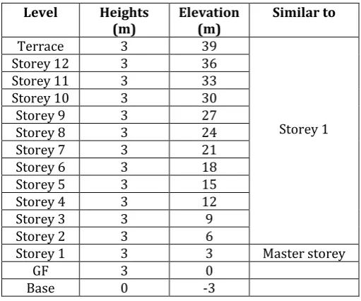
A G+12 Storey R.C. building, a real structure which is under construction in Mumbai is considered for the present study to investigate SSI effects on R.C. buildings. The plan dimension of the building is 12.46 m x19.40 m and the height of the building is 39 m from the ground level. Elevation and storey details are shown in TABLE I.
[image:1.595.306.562.457.670.2]Mumbai falls under Seismic Zone-III of IS 1893-2002 is located in a coastal region and structures are exposed to coastal environment and surfaces of buildings are protected by plastering and painting coats. As per IS 456-2000 (Table 3), moderate exposure condition shall be considered in design. Basic wind speed for Mumbai, Vb is 44 m/sec.
Table -1: Heights and Elevation of Storey
Level Heights
(m) Elevation(m) Similar to
Terrace 3 39
Storey 1
Storey 12 3 36
Storey 11 3 33
Storey 10 3 30
Storey 9 3 27
Storey 8 3 24
Storey 7 3 21
Storey 6 3 18
Storey 5 3 15
Storey 4 3 12
Storey 3 3 9
Storey 2 3 6
Storey 1 3 3 Master storey
GF 3 0
Base 0 -3
3. METHODOLOGY
Following methodology is adopted for analysis work:
© 2019, IRJET | Impact Factor value: 7.211 | ISO 9001:2008 Certified Journal
| Page 714
2. Analysis of R.C. building without considering SSIthat is fixed base support using ETABS.
3. Modeling and analysis of Raft foundation of building with considering SBC of soil by using SAFE. 4. Modeling and analysis of R.C. building on raft and
soil spring together that is flexible base support using ETABS.
5. Comparison of results
4. Modeling and Analysis of R.C. Building
[image:2.595.308.560.228.383.2]The 12 story building modeled using ETABS software for ease of modeling. The whole building is modeled as three dimensional R.C frame model. Details of beam, slab and column sections used in modeling are shown in TABLE 2. Details of structural loading and seismic parameters applied for analysis are shown in TABLE 3.
Table -2: Beam, Slab and Column section Details
Sr.
No. Elements Sections (mm) Concrete Grade of
Beam
150X320
M25 150X450
1 150X600
230X600 230X450
One way Slab
120
M25
2 150
3 Two way Slab 120
150 4 Shear Walls/
Column
230X300
M40 230X380
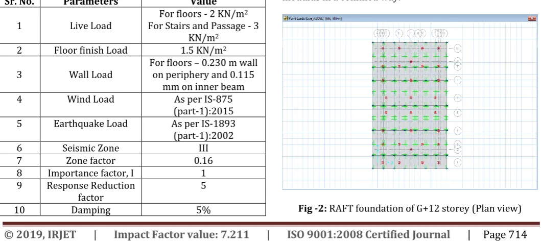
Table -3: Details of Structural loading data considered
Sr. No. Parameters Value
1 Live Load For floors - 2 KN/m
2
For Stairs and Passage - 3 KN/m2
2 Floor finish Load 1.5 KN/m2
3 Wall Load For floors – 0.230 m wall on periphery and 0.115 mm on inner beam
4 Wind Load As per IS-875
(part-1):2015 5 Earthquake Load As per IS-1893 (part-1):2002
6 Seismic Zone III
7 Zone factor 0.16
8 Importance factor, I 1
9 Response Reduction
factor 5
10 Damping 5%
4.1 R.C. Building with Fixed Base
The co-ordinate points are the placements of columns according to the base plan layout of the structure. All the points will be constrained with ux, uy, uz, rx, ry and rz coordinates for fixed base condition, which means no linear and rotational displacements are allowed. The complete building has been modeled using appropriate elements of beams, columns and slabs in each storey. The plan and three dimensional view of the R.C. building is as shown in Fig. 1.
Fig -1: G+12 storey building at fixed base (Plan & 3D view)
4.2 Modeling and Analysis of Raft foundation
The design of raft foundation is done for the same building using software SAFE. The SBC of soil is 200 KN/m2 with
permissible settlement 15 mm. The equivalent sub -grade modulus is 13333.33 KN/m3.The DL, LL, WL, Earthquake
[image:2.595.36.288.332.518.2]Load and Load combination above base of G+12 storey building are directly imported from ETABS, The thickness of raft slab of 1m has been provided and grade of concrete for analysis is M30. The size of raft is 13.96mx21.40m. Raft slab is divided into 10 x 7 panels for providing sub -grade modulus in a confined way.
[image:2.595.32.562.557.793.2]© 2019, IRJET | Impact Factor value: 7.211 | ISO 9001:2008 Certified Journal
| Page 715
Fig -3: Snip of Loading above RAFT (3D view)
Building loading with raft as 2D plate element with fixed boundary condition has been analysed. Reaction (P) at each node of element has been obtained. The raft has been analysed with considering soil subgrade modulus with permissible settlement to obtain the displacement (∆) at each node.
4.3 Modeling and Analysis of R.C. Building with
Flexible Base
The modelling of same R.C. building with raft is done using ETABS. The soil stiffness has been calculated by using eq.1 and applied at each node. The building with raft and soil spring is shown in fig -5.
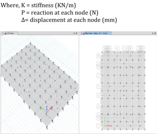
K= P/∆ ……….. (1)
Where, K = stiffness (KN/m)
P = reaction at each node (N) ∆= displacement at each node (mm)
[image:3.595.38.334.56.277.2]Fig -4: Assigning of soil point spring under raft
Fig -5: G+12 storey building at flexible base (3D view)
5. Result and Discussion
Structural response has been studied with respect to storey drift, Storey displacement, base shear and natural time period of R.C. building without SSI (fixed base) and building with SSI (flexible base). Results obtained are compared by using graphs.
5.1 Story Drift Ratio Response
[image:3.595.40.540.487.724.2]Story drift ratio is the maximum relative displacement of each floor divided by the height of the same floor. The comparison of storey drift ratio of R.C. building on fixed base (NSSI) and flexible base (SSI) conditions in earthquake X and Y direction are shown in fig- 6 and fig- 7.
Figure -6 shows that story drift ratio distribution of 12-story model
in X-direction
increases gradually and reaches its maximum value in the 6th story level. The maximum valuesfor NSSI and SSI in EQX-direction are 0.001524 and 0.001777 respectively.
-10 0 10 20 30 40 50
0 0.0005 0.001 0.0015 0.002
El
ev
at
io
n
(m
)
Drift (unitless) Storey Drifts in X-direction
NSSI SSI
[image:3.595.35.286.509.723.2] [image:3.595.311.555.545.683.2]© 2019, IRJET | Impact Factor value: 7.211 | ISO 9001:2008 Certified Journal
| Page 716
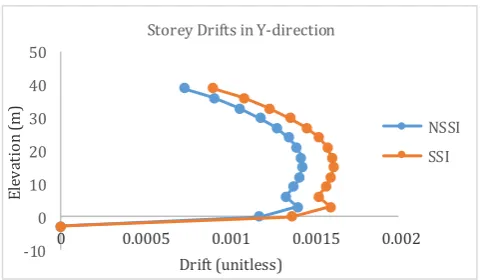
Figure -7 shows that story drift ratio distribution of 12-storymodel in Y-direction increases gradually and reaches its maximum value in the 5th story level. The maximum values
for NSSI and SSI in EQY-direction are 0.001429 and 0.001613 respectively.
-10 0 10 20 30 40 50
0 0.0005 0.001 0.0015 0.002
El
ev
at
io
n
(m
)
Drift (unitless) Storey Drifts in Y-direction
NSSI SSI
Fig -7: Storey drift ratio response comparison for fixed (NSSI) and flexible base (SSI) conditions in EQY
[image:4.595.41.285.172.312.2]5.2 Storey Displacement Response
Figure 8 and 9 shows that story displacement profile over building height of 12-story increases nonlinearly with the structural height. The maximum displacement response in EQX direction for NSSI and SSI models are 55.88 mm and 66.47 mm respectively.
-10 0 10 20 30 40 50
0 20 40 60 80
Elev
at
io
n
(m
)
Displacement (mm)
Maximum Storey Displacements in X-direction
NSSI SSI
Fig -8: Storey displacement response comparison for fixed (NSSI) and flexible base (SSI) conditions in EQX
The maximum displacement response in EQY direction for NSSI and SSI models are 52.39mm and 60.05mm respectively.
-10 0 10 20 30 40 50
0 20 40 60 80
El
ev
at
io
n
(m
)
Displacement (mm)
Storey Displacements inY-direction
NSSI SSI
Fig -9: Storey displacement response comparison for fixed (NSSI) and flexible base (SSI) conditions in EQY
5.3 Base Shear Response
The base shear value for fixed and flexible base condition are constant value of 382.5483 and 477.0707 in earthquake direction X and Y respectively by using equivalent static method. The story shear response obtained is independent of SSI effects and depends only on the building weight.
5.4 Natural Time Period
In Modal analysis the building is analysed as a continuous model with finite number degrees of freedom and natural frequencies. The Natural time periods are the important factors, which affect the seismic behaviour of the structure. Natural time periods obtained from the analysis of fixed base and flexible base support conditions are shown in Table- 7.
Table -4: Modal Behaviour of Building
Model No.
Period (sec)
Fixed Base Flexible Base
1 2.816 3.063
2 2.639 2.703
3 2.454 2.607
4 0.876 0.877
5 0.821 0.821
6 0.78 0.781
7 0.477 0.478
8 0.446 0.446
9 0.433 0.434
10 0.331 0.331
11 0.311 0.331
[image:4.595.42.285.462.605.2]© 2019, IRJET | Impact Factor value: 7.211 | ISO 9001:2008 Certified Journal
| Page 717
02 4 6 8 10 12 14
0 1 2 3 4
M
od
al
N
um
be
r
Perio (sec) Natural Time Period
[image:5.595.42.283.98.242.2]NSSI SSI
Fig -10: Natural time period comparison with respect to mode numbers for fixed and flexible base conditions
5.5 Bending Moment Variations
The bending moment variation of beam of R.C. building has been studied on seismic response and also under the effect of gravity load i.e. 1.5 (DL+LL) for both fixed and flexible base conditions. Beam B139 at first floor has been taken for study. Table -8 shows the bending moment variations in selected beam.
Table -5: Bending Moment variation of selected Beam
Sr. No. Load
conditions Fixed Base Moment (kN-m) Flexible Base
1 EQX +59.91 +60.77
2 EQY -9.43 -10.54
3 1.5 (DL+LL) -40.56 -38.99
6. CONCLUSIONS
R.C. building of G+ 12 storeys with fixed base has analysed with and without considering SSI. SSI has been incorporated by using soil springs. Equivalent static method is used to analyse the structure response as per IS 1893 (Part-I) 2002. Seismic response results of flexible base in terms of storey drift, storey displacement, base shear and modal behavior are compared with fixed base condition.
The following conclusions are drawn after comparing the responses of both support conditions.
(a) Variation of storey drift in both the cases is parabolic with middle storeys showing maximum drift. When SSI is considered there is a magnification of storey drift in the middle storeys. (b) The effect of SSI on the story lateral displacement 12-story buildings has been studied. It is observed that the displacement increase occurs in SSI models. (c) The natural time period in case of building with fixed base in first mode is 2.816 sec and increases to 3.635 sec in case of flexible base condition.
Similarly, an amount of increase in the natural time period is found in all model.
(d) The mass participation ratio of first three modal of R.C. building in case of fixed support condition are 82.24% and 83.37% in x and y direction respectively. Similarly, in case of flexible base condition decreases to 75.64% and 76.65%. (e) Under the effect of seismic load the bending
moment of beam slightly increases under effect of SSI. Under the gravity load the bending moment of beam is higher in case of fixed base condition. (f) The response of R.C. building has shown significant
increase compared to conventional approach of assuming fixed base.
REFERENCES
[1] Bhojegowda V. T. and Mr. K. G. Subramanya, “Soil
Structure Interaction of Framed Structure Supported on Different Types of Foundation,” International Research Journal of Engineering and Technology, Volume 02, 2015, Issue 05, pp.651-660.
[2] Christos Giarlelis and George Mylonakis, “The role of
soil-structure interaction in the inelastic performance of multi-storey buildings,” Proceedings of the 9th International Conference on Structural Dynamics, Porto, Portugal, 2014, pp.507-513.
[3] H. Matinmanesh and M. Saleh Asheghabadi, “Seismic
Analysis on Soil-Structure Interaction of Buildings over Sandy Soil,” The Twelfth East Asia-Pacific Conference on Structural Engineering and Construction, Procedia Engineering 14, 2011, pp.1737–1743”.
[4] Jiang Xinliang and Zhang Yanan, “Influence of Structure
Plane Size on Seismic Response of Soil-Structure Interaction,” World Earthquake Engineering, Volume 19 2013, pp. 345-350.
[5] Kamala Kumari and Dr. S. R. K. Reddy, “Influence of
Soil-Structure Interaction on Response of a Multi-Storied Building against Earthquake Forces,” International Journal of Science and Research, Volume 5, 2016, Issue 6 pp.2194-2198.
[6] Mr. Kotkar R.K. and Prof. Patankar J. P., “Effect of Soil
Structure Interaction on Buildings with Stiffness Irregularity under Seismic Load,” International Research Journal of Engineering and Technology (IRJET), Volume 04, 2017, Issue 07, pp.1156-1165.
[7] Shehata E. Abdel Raheem, Mohamed M. Ahmed and
Tarek M. A. Alazrak, “Evaluation of soil–foundation– structure interaction effects on seismic response demands of multi-story MRF buildings on raft foundations,” International Journal of Advance Structural Engineering, Vol. 7(1), 2015, pp.11-30.
[8] S. K. Dugggal (2013). Earthquake Resistant Design of
Structures: Oxford University Press, pages 140-143.
[9] Sagar Karki Chhetri and Kamal Bahadur Thapa, “Soil