warwick.ac.uk/lib-publications
A Thesis Submitted for the Degree of PhD at the University of Warwick
Permanent WRAP URL:
http://wrap.warwick.ac.uk/102599
Copyright and reuse:
This thesis is made available online and is protected by original copyright.
Please scroll down to view the document itself.
Please refer to the repository record for this item for information to help you to cite it.
Our policy information is available from the repository home page.
Propagation Studies and Modulation Techniques
for a Distributed Architecture Rural Radio-Telephone
System
Simon Browne
Contents
1 I n tr o d u c tio n 1
1.1 In trodu ction ... 2
1.2 Telecommunications and the Developing World ... 2
1.2.1 The Need for Telecommunications... 2
1.2.2 Applications o f Telecommunications... 3
1.2.3 Economic Considerations... 3
1.2.4 System Requirements... 4
1.3 The Use o f R a d i o ... 5
1.3.1 Current Systems in Use ... 6
1.3.2 A Lower-Cost S o lu tio n ... 7
1.4 The Novel Network - Overview ... 8
1.4.1 Station D escrip tion ... 11
1.4.2 Protocol D e s cr ip tio n ...12
1.4.3 Radio Considerations . . ...14
2 P r o p a g a tio n B a ck g ro u n d and M ea su rem en t R esu lts 20 2.1 Radio P r o p a g a tio n ...21
2.1.1 VHF/U HF P r o p a g a tio n ... 21
2.1.2 Multipath P ropagation ... 30
2.1.3 Characterizing multipath channels... 34
2.1.4 Propagation Measurements in Sierra L e o n e ... 36
11 CONTENTS
2.2 R esu lts...37
2.2.1 Transmission Loss R e s u lt s ... 40
2.2.2 Multipath R esu lts... 41
3 P r o p a g a tio n M e a su re m e n t H ard w a re 56 3.1 In trod u ction ...57
3.2 Multipath Characterization using Pseudo-Random Binary Sequences 57 3.3 Measurement Equipment Implementation... 59
3.3.1 Transmitter H a r d w a r e ...60
3.3.2 Receiver H a r d w a r e ... 60
3.4 Transmission-loss measurem ents... 62
3.5 Calibration o f the receiving e q u ip m e n t...62
3.5.1 Receiver detector calibration ... 62
3.5.2 System transmission loss calibration... 63
3.5.3 Post-processing o f delay profile d a t a ... 64
3.5.4 Hardware Limitations ...65
3.5.5 A Note on Later Work in T a n z a n ia ... 70
4 M o d u la tio n B a ck g ro u n d a n d Im p le m e n ta tio n C o n sid e ra tio n s 72 4.1 In trod u ction ... 73
4.2 M o d u la t io n ... 73
4.2.1 Digital Modulation Techniques ... 73
4.2.2 Power and Spectrum E ffic ie n c y ...75
4.2.3 Efficiency Requirements o f the Rural Radio S y s t e m ... 76
4.2.4 QPSK, OQPSK and M S K ... 77
4.2.5 The need for filte rin g ... 78
4.2.6 Variations on QPSK and MSK : 7r/4-QPSK and GMSK . . . . 81
4.2.7 Constraints Placed Upon the Modulation Scheme by the System 83 4.3 Use o f tt/4 -D Q P S K ... 87
CONTENTS
i i i
4.5 EPROM Look-Up Implementation of 7t/ 4-DQPSK filte rin g ...99
4.5.1 Ramping U p /D o w n ... 105
5 D igital M o d u la t o r Im p lem en tation 109 5.1 Digital Modulator Implementation ... 110
5.1.1 Digital vs analogue approaches ... I l l 5.2 An EPROM look-up source of 7t/ 4-DQPSK I and Q d a t a ... 113
5.2.1 Distortion effects in the look-up te c h n iq u e ... 117
5.2.2 Differential phase encoder im plem en tation... 117
5.2.3 Generation of filtered co e ffic ie n ts ... 120
5.2.4 Generation of ramping coefficients...121
5.2.5 Quadrature m o d u la to r ...122
5.2.6 Practical results... 124
6 E n v e lo p e E lim in a tion a n d R e sto ra tio n T ran sm itter Im p lem en ta tio n 128 6.1 In trodu ction ...129
6.1.1 Modes o f nonlinear power amplifier o p e r a t io n ...129
6.2 Power amplifier linearization techniques... 131
6.2.1 Linear amplification using non-linear components (LINC) . . .132
6.2.2 Cartesian fe e d b a c k ... 133
6.2.3 P re-d istortion ...135
6.2.4 Envelope elimination and re s to ra tio n ... 136
6.2.5 PA high-level modulation te c h n iq u e s ... 137
6.3 A practical 53 MHz P A ... 141
6.3.1 Up-converter and 53 MHz amplifiers ... 141
6.3.2 PA c ir c u itr y ... 142
6.3.3 Simulation results... 143
6.3.4 Modulator circu itry... 152
IV CONTENTS
6.3.6 Phase f e e d b a c k ...153
6.3.7 Practical spectra in the EER s y s t e m ... 154
7 N on -lin ea rities in E n v e lo p e E lim ination and R e sto ra tio n S ystem s 160 7.1 Non-linearities in Envelope Elimination and Restoration Systems . . .161
7.2 Modelling non-linearities...161
7.3 Amplitude modulation (AM ) and AM -AM d is t o r t io n ... 162
7.4 Phase modulation (PM ) and AM -PM d is to r tio n ... 164
7.5 Combined AM and P M ...165
7.5.1 Results of non-linearities in the modulation p ro c e s s e s ... 166
7.6 Modelling the effects o f AM -AM and AM-PM distortion on 7t/4-DQPSK168 7.6.1 R esu lts... 173
8 C o n clu sio n s 176 8.1 Discussion o f propagation results ...177
List of Figures
1.1 Diagram illustrating system operation... 10
1.2 Diagram illustrating short packet stru ctu re... 12
1.3 Diagram illustrating circuit burst stru ctu re...14
2.1 Diffraction around knife edge ... 24
2.2 Diffraction around smooth s p h e r e ... 24
2.3 Diagram illustrating first Fresnel z o n e ...25
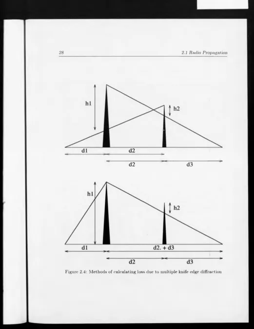
2.4 Methods o f calculating loss due to multiple knife edge diffraction . . . 28
2.5 Diagram illustrating ray profiles for several values o f k ...30
2.6 Diagram illustrating multipath propagation in a hilly r e g i o n ... 33
2.7 Autocorrelation o f pseudo random binary s e q u e n c e ... 35
2.8 Channel measurement output for a multipath ch an n el... 35
2.9 Path profiles from K a b a l a ... 38
2.10 Path profiles from K a b a l a ...39
2.11 Path profile from Kabala to Bambukoro, showing main ridges . . . . 40
2.12 Table showing measured and predicted transmission l o s s e s ... 42
2.13 Delay profile: Aberdeen Pt. - Tower Hill, Freetown, averaged over 16 measured p r o file s ...44
2.14 Delay profile: Aberdeen Pt. - Congo Cross, Freetown, averaged over 11 measured p r o f i l e s ... 45
2.15 Delay profile: Aberdeen Pt. - Clinetown, Freetown, averaged over 38 measured p r o file s ...46
VI LIST OF FIGURES
2.16 Delay profile: Kenema - Panderu, averaged over 62 measured profiles 47
2.17 Delay profile: Kenema - Lago, averaged over 86 measured profiles . . 48
2.18 Delay profile: Kenema - Gilehun, averaged over 22 measured profiles . 49 2.19 Delay profile: Kabala - Yanffurandor, averaged over 22 measured p ro file s... 50
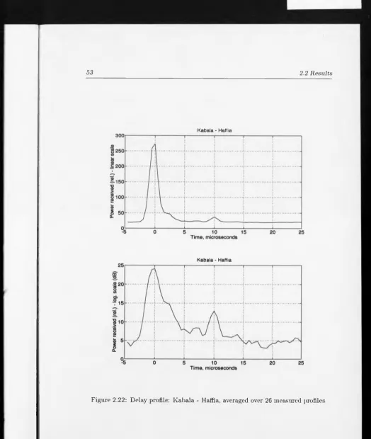
2.20 Delay profile: Kabala - Forenaya, averaged over 59 measured profiles . 51 2.21 Delay profile: Kabala - Sonkonya, averaged over 3 measured profiles . 52 2.22 Delay profile: Kabala - Haffia, averaged over 26 measured profiles . . 53
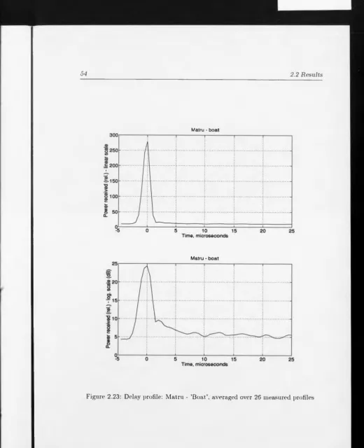
2.23 Delay profile: Matru - ’Boat’ , averaged over 26 measured profiles . . . 54
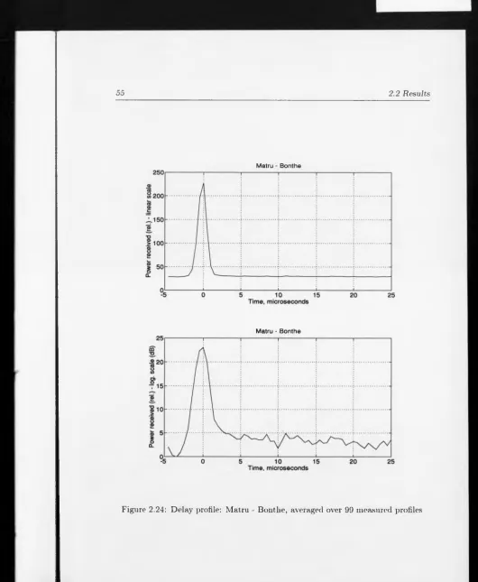
2.24 Delay profile: Matru - Bonthe, averaged over 99 measured profiles . . 55
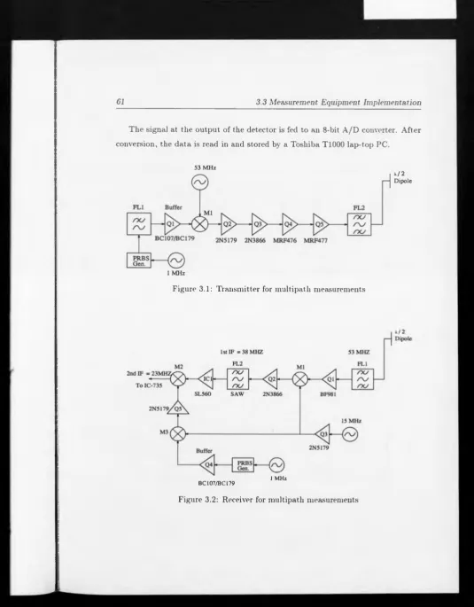
3.1 Transmitter for multipath m easurem ents... 61
3.2 Receiver for multipath m easurem ents... 61
3.3 Graph showing AM detector vs. product detector responses ...63
3.4 Illustration o f technique used in averaging delay p rofiles... 66
3.5 Comparison o f single profile with averaged profiles... 67
3.6 Comparison o f single profile with averaged profiles, plotted on log. sca le s... 68
4.1 QPSK modulator implementation and signal constellation diagram with phase transitions ... 79
4.2 7r/4-DQPSK signal space diagram and phase m apping...83
4.3 Impulse responses o f root raised cosine filters...91
4.4 Constellation diagrams o f 7r/4-DQPSK signals with root raised cosine filters... 92
4.5 Constellation diagrams o f 7t/ 4-DQPSK signals with cascaded root raised cosine f i l t e r s ...93
LIST OF FIGURES vii
4.7 Baseband spectra with root raised cosine filtering o f roll-off 0.25 and
different truncation length s... 95
4.8 Baseband spectra with root raised cosine filtering o f roll-off 0.5 and different truncation len gth s... 96
4.9 Baseband spectra with root raised cosine filtering o f roll-off 0.75 and different truncation len gth s... 97
4.10 Baseband spectra with root raised cosine filtering o f roll-off 1.0 and different truncation len gth s... 98
4.11 Impulse responses o f Kingsbury filters...100
4.12 Baseband spectra for 7t/ 4-DQPSK filtered by Kingsbury filters . . . . 101
4.13 Signal constellation diagrams for 7t/ 4-DQPSK filtered with Kingsbury filter: upper traces - transmitter output, lower traces - output from two identical filters ca s c a d e d ...102
4.14 Implementation o f 7T/4-DQPSK phase and amplitude generation us ing EPROM l o o k - u p ... 104
4.15 Spectra for 7r/4-QPSK transmitted with and without filter ’tails’ . . . 108
5.1 7r/4-DQPSK baseband generator...113
5.2 7t/ 4-DQPSK I and Q eye diagrams for rectangular baseband data . . 115
5.3 7r/4-DQPSK modulator implementation using EPROM look-up . . .1 1 6 5.4 Diagram showing typical output spectrum from digital synthesis cir cuitry ...118
5.5 7t/4-DQPSK differential phase e n c o d e r ...119
5.6 Address word stru ctu re...121
5.7 7t/ 4-DQPSK quadrature modulator im plem en tation ... 122
5.8 I-channel data generated by look-up technique ... 125
5.9 Spectrum o f I-channel data generated by look-up technique ... 126
5.10 Spectrum o f tt/ 4-DQPSK generated by quadrature modulation . . . . 127
LIST OF FIGURES viii
6.2 Diagram illustrating cartesian feedback im plem entation... 134
6.3 Diagram illustrating envelope elimination and restoration implemen tation ... 136
6.4 Power amplifier c i r c u i t ... 143
6.5 Waveforms in saturating P A ...145
6.6 Phase vs. supply voltage for simulated c i r c u i t ...146
6.7 Output signal amplitude vs. supply voltage for simulated circuit . . . 147
6.8 Efficiency vs. supply voltage for simulated c i r c u i t ...148
6.9 Amplifier performance vs. series inductance for simulated circuit . . . 149
6.10 Practical PA output network...150
6.11 Phase shift vs. output power for practical circuit...151
6.12 Envelope detector and high-level modulator circuit ...152
6.13 Envelope feedback and modulator c i r c u it ... 153
6.14 Spectrum o f low-level 53 MHz 7t/4 -D Q P S K ... 155
6.15 Spectrum o f low-level 53 MHz burst d a t a ... 156
6.16 Spectrum o f limited 53 MHz tt/4-D Q PSK ... 157
6.17 Spectrum o f PA output (1) 53 MHz 7r/4-DQPSK ... 158
6.18 Spectrum o f PA output (2) 53 MHz tt/4-D Q PSK ... 159
7.1 Phasor diagram showing AM and PM sid eba n ds... 167
7.2 Plots o f phase and amplitude response vs. V s ... 169
7.3 Diagram o f non-linearity simulation p ro c e d u re ... 171
7.4 Diagram showing AM and PM effects on an instantaneous signal . . .1 72 7.5 Spectra o f filtered baseband (lower) and limited (upper) signals . . .1 7 3 7.6 Spectra after phase distortion only (dashed) and after amplitude dis tortion only ( s o l i d ) ... 174
Acknowledgments
I would mainly like to thank my supervisor, Dr Steve Chandler, o f War
wick University for his guidance and support throughout the period o f the
work. The knowledge that he would always find time to help with problems
was very re-assuring, and his constant commitment greatly appreciated.
For the propagation work, thanks are due to Ken Stealey, who was also
working on the system at the time, for writing the software to allow the
recording, and displaying, o f the received data on the Toshiba PC. Also, Prof.
B. Honary, now o f Lancaster University, is thanked for allowing the use of
one o f the Icom transceivers belonging to his group. For actual measurement
work, SLNTC were extremely helpful in providing a vehicle, technician and
driver for the period. Many Sierra Leonians helped in the measurement
work, operating the transmitter, helping to put up aerials etc., which was
very important for success o f the work.
The Science and Engineering Research Council, SERC, are thanked for
IF ISI LINC LO LOS MSK NRZ PA PM PSK PRBS QAM QPSK RF ROM SSB TDD TDM A Intermediate frequency
Inter-symbol interference
Linear transmitter using non-linear components
Local oscillator
Line o f sight
Minimum shift keying
Non return to zero
Power amplifier
Phase modulation
Phase shift keying
Pseudo-random binary sequence
Quadrature amplitude modulation
Quadrature phase shift keying
Radio frequency
Read only memory
Single sideband
Time-division duplex
Time-division multiple access
IF ISI LINC LO LOS MSK NRZ PA PM PSK PRBS QAM QPSK RF ROM SSB TDD
TD M A
Intermediate frequency
Inter-symbol interference
Linear transmitter using non-linear components
Local oscillator
Line o f sight
Minimum shift keying
Non return to zero
Power amplifier
Phase modulation
Phase shift keying
Pseudo-random binary sequence
Quadrature amplitude modulation
Quadrature phase shift keying
Radio frequency
Read only memory
Single sideband
Time-division duplex
Time-division multiple access
Abstract
The work described in this thesis forms part o f the development of a
novel digital distributed radio network. In particular, the areas o f radio
propagation and modulation are considered.
Field measurements o f radio channel characteristics made in Sierra Leone
are described. The results are presented, together with a description o f the
implementation o f the measuring equipment. Both transmission loss and
channel impulse responses were measured. Measured loss values are com
pared with theoretical values calculated using standard routines. The mea
surements were made at a frequency o f 53 MHz.
The implementation o f a spectrally efficient modulation scheme using a
power efficient transmitter is detailed. Transmitter lineal.zation schemes are
described. Consideration is also given to filtering techniques applicable to
look-up table based transmission. An overall transmitter has been produced,
operating at 53 MHz, and the results are given.
2 1.1 Introduction
1.1
Introduction
This chapter gives the background to the work presented in the thesis. After some
general information on the application of the work, the radio system under devel
opment is briefly described. The modulation and propagation aspects, with which
this work has been concerned, are then mentioned.
1.2
Telecommunications and the Developing W orld
1.2.1 The Need for Telecommunications
Whilst the telephone is generally taken for granted as being part o f life in the devel
oped world, there exists an enormous number o f people throughout the developing
world having no access whatsoever to this technology [12].
For the vast majority, if not all, developing countries there is some form of
communications infrastructure in the larger towns and cities, however it is a very
different situation in the rural areas. It can be argued that the rural areas actually
provide almost all o f the income for these countries from such activities as agricul
ture, mining and tourism, since generally the cities produce little, serving in the main
as administration and service centres. The rural communities therefore deserve con
sideration when it comes to encouraging a country’s growth, and in the distribution
o f its wealth. Since in many cases these communities do not actually benefit to any
significant degree from the wealth generated, the standard o f services available and
general living conditions may be inferior to those in the cities. Certainly the cities
offer some opportunities o f finding material wealth and types o f work not found in
the rural areas, and although these opportunities may actually present themselves
to only a very small minority, it is sufficient reason for many to leave the rural areas
for the cities in the hope o f a better life. The country’s economy will rarely benefit,
on the whole, from this migration however, since this extra workforce is likely to be
3 1.2 Telecommunications and the Developing World
with this population shift are well-known, and are in evidence in many cities in the
developing world. If the quality o f life could be improved in the rural areas, however,
people may be less inclined to leave, and instead stay and actively contribute to the
wealth and well-being o f the community. B y creating some degree o f telecommuni
cations infrastructure, many of the hindrances to providing reasonable services may
be removed and people would feel far less isolated than previously [3, 4, 10].
1.2.2
Applications of Telecommunications
Health care and agriculture are two examples of the areas in which telecommuni
cations could play a major role. It is obvious that the ability for remote villages
to have a communication link with a hospital or health centre would increase the
response time to any need for medical aid, and the value o f the potential to pass
medical advice verbally to remote areas could be great in a large number o f situa
tions. The worth o f such an infrastructure in cases o f natural disaster is difficult to
over-estimate, in the co- ordination o f any relief effort and in the general gleaning
o f information on the situation. For agriculture, telecommunications can offer a
great saving in time for many routines necessary in farming life in remote areas:
information on markets would be instantly available, with farmers knowing where
their crops could be sold, and for what price; advice on mechanical problems with
machinery would be available without the need to travel to the nearest mechanic,
spare parts could be ordered easily, and deals with suppliers could be decided with
out an actual meeting. Research in the past by such organisations as the ITU
has suggested significant, and in some cases enormous, ’cost-to- benefit’ ratios for
telecommunication services in rural areas [4].
1.2.3
Economic Considerations
Despite the above, funding for telecommunications is likely to be inadequate for
4 1.2 Telecommunications and the Developing World
cost o f many rural telecommunications products, the designs o f which are not well
matched to needs o f the rural areas o f developing countries. There must be, then,
a great desire throughout the developing world for a low cost telecommunication
system designed specifically to meet the needs o f the people in the rural areas.
1.2.4
System Requirements
Having identified the need for telecommunications equipment in these areas, the
first question to be asked is what type o f equipment is required. This, however, is a
very difficult question to answer, as it depends on large number o f factors particular
to the areas in where the equipment would be employed [9]. There are a number o f
problems faced in the installation and operation o f a network in such remote areas,
all o f which must be carefully considered in the network design, some o f the most
important being the following
• Lack o f existing infrastructure (power, roads etc.).
• Difficult terrain.
• Harsh or severe climate.
• Low density o f population (and very low densities o f telephones due to the low
number o f telephones per head o f population).
• Low potential revenue.
• Poor maintenance o f equipment.
From the above, it is clear that there are large differences in system require
ments between the ’developed’ and developing’ worlds. The optimal solution to
one is therefore likely to be far less optimal to the other. The general policy of
applying perhaps inappropriate solutions to the above problems therefore ought to
5 1.3 The Use o f Radio
specifically for the developing world, and that some o f the existing lower cost equip
ment should be instead used. At first thought there appears to be substantial merit
in this argument, however when the size of the potential market for the equipment
is considered it can be seen that there are good reasons to attempt the design o f a
system aimed specifically at this problem.
The work initiated by Chandler [11] addresses the above problems well, with the
idea of a novel radio network entirely suitable for the majority o f cases in the devel
oping world. The design is based around serving areas containing villages distributed
in a fairly random manner, without the need for any existing infrastructure.
One important idea suggested was that of the spacing o f telephones; it was con
sidered that a basic service should provide sufficient telephones to limit the distance
people must travel in order to reach one, to ensure that people would not be deterred
from sending messages. A figure of 5 km was considered reasonable as a guideline
to be used in basic system calculations. This figure would put one telephone in
every 77.5 sq.km were a circular coverage used, leading to the approximation of
telephone density to 0.01/sq.km. If this figure was applied to an area the size of
Africa, around 300,000 telephones would be required. Figures such as these are ex
tremely important in the design of an optimal network, and equally so in indicating
the applicability o f present technology to the areas being considered.
1.3
The Use o f Radio
It is apparent that radio transmission is the most appropriate technique for telecom
munications in by far the great majority o f rural areas o f developing countries [8].
The inhospitable terrain and climate create huge problems in themselves, and, with
the large cost in laying any form o f cable system, line transmission has many disad
vantages. Radio solutions can overcome many of the problems facing line systems:
installation costs are low; installation time and complexity are low; no servicing
6 1.3 The Use o f Radio
are not required to be placed in remote locations); additional terminals (telephones)
can generally be installed and integrated into any existing system without major
problems.
1.3.1
Current Systems in Use
As a means o f providing communications in rural areas o f the developed world, sev
eral types o f system employing radio technology have been developed [8]. Multiple-
access systems and satellite systems have been put into service in large areas and
found to work well, although at substantial financial cost. On a less sophisticated
scale, there has been use o f single channel radio systems serving remote areas, with
the use o f repeaters where necessary. Whilst these systems may serve their pur
poses well, they are not, as previously stated, ideal for applications considered in
the developing world. The satellite [2] and multiple-access schemes [5, 6, 7] both
rely upon a reasonably high grouping o f subscribers around earth stations or out-
stations, respectively, to becom e economic. On a one-telephone-per-village basis,
such subscriber densities will be reached rarely, if at all, in the developing world.
Additionally, multiple-access schemes are designed to ’branch out’ from existing,
typically radial, telecommunication networks, and such networks are by no means
common in the areas under consideration.
The fixed frequency links using repeaters are not suited to serving anything other
than the smallest numbers o f subscribers,, being limited by the number o f available
channels and due to the fact that repeaters in remote locations are highly undesirable
because o f the problem o f maintenance. The use o f cellular radio technology to
serve rural areas [1] is becoming increasingly popular, however this approach is not
well suited to the small subscriber densities, and would require a large number o f
base stations and digital switches at various locations, calling for a certain degree
o f infrastructure and costly exchanges. Due to the low subscriber densities, each
1.3 The Use o f Radio
the unit station cost that much more. As an example, for a base station with a
coverage radius o f 30km and a telephone density o f 0.01/sq.km, only approximately
30 stations would be served. The individual station unit costs, together with the
share o f the base station costs and o f the hierarchy further up, would make the
cellular approach a costly one in such an area.
Of course, where the distribution of required telephones differs significantly from
the case assumed above, the relative merits o f the other systems mentioned will
change. If subscriber densities increase, then it may become feasible for the TDMA
(time-division multiple access) or cellular type systems to be used, for example.
1.3.2
A Lower-Cost Solution
As a first step in providing a more suitable communications service, Dr Steve Chan
dler o f Warwick University installed a basic network o f solar powered, microproces
sor controlled CB transceivers in the Bonthe region o f Sierra Leone, West Africa
[13, 17]. This system certainly met the criterion o f low-cost, since the equipment in
each station would total a value o f around three hundred pounds, which would be
far less than any other available system station costs, typically greater than 1000
pounds. Operating at 27MHz, a maximum range o f approximately 50 miles was pos
sible with the CB units over flat terrain, and with good conditions. Unfortunately,
ionospheric propagation led to interference from other stations in distant countries,
and, peaking in the afternoon, this interference limited range to the order o f only
5 miles. The control units permitted selective calling o f other stations, in addition
to serving a control purpose for the provision o f details o f station states and other
functions. This system is still in operation.
Whilst the performance o f such a basic network is obviously rather limited,
it serves the purpose o f a local network in areas with no existing infrastructure
very well indeed. Certainly, a system such as this works as a useful reference for
8 1.4 The Novel Network - Overview
market. The Bonthe network showed that where cost is o f paramount importance,
a network o f CB (or VHF FM) radios, solar powered, could be a viable solution
to some o f the problems o f rural communications in, primarily, the least developed
regions o f the world. The interference situation could be solved by changing to a
higher-frequency system.
Unfortunately, such ’simple’ radio networks are very limited in a number of ways.
Range is limited to that allowed by the radio propagation, which with low power
systems will be in the region of 40 - 50 km (assuming the use o f VHF and relatively
flat terrain), and therefore long distance communication is not generally possible,
although the manual relaying o f messages could be used in some instances. There
would be no guaranteed privacy involved with the network, since any station could
monitor the transmissions of all other stations within range, which has implications
for the suitability o f the system for calls of, for example, a business or very personal
nature.
Analysis on the use o f the network in the area has provided useful information
on requirements o f any service intended for this application, such as amount o f time
each ’telephone’ is in operation, and the range o f distances of calls made. Statistics
like these are crucial for effective system design, and appear to be very scarce, as few
small villages have been served by any telephone system in the developing world.
1.4
The Novel Network - Overview
As mentioned previously, Dr Chandler at Warwick has proposed a novel approach
to providing a telecommunication service well suited to rural areas o f developing
countries. The system has drawn on data gathered from his pilot system in Bonthe,
and uses equipment designed specifically for the task.
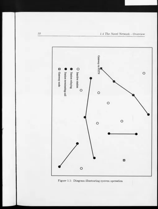
A basic overview o f the system is as follows:- Stations (radio/telephones) are of
identical form, and can act as either a terminal or a repeater at any time. An area
9 1.4 The Novel Network - Overview
number o f stations located in a distributed manner around the region. It is assumed
that there would be a station in most reasonably sized villages, with an approximate
station density, as previous given, o f 0.01 per square kilometre. ’Gateway’ nodes
are located within the network, these being stations which are already connected to
the normal public telephone network, if one exists. They enable calls to be routed
into and out o f the distributed radio network. The ability o f stations to act as relay
stations allows calls to be made over distances well beyond the normal radio horizon,
and the use o f digital transmission is crucial in the preservation o f signal quality
across such a link o f relays. An illustration o f the operation o f the network is given
in figure 1.1.
Stations would be solar powered, with battery back-up, where no mains electric
ity infrastructure exists. Calls are set up on a common ’calling channel’ , employing
packet radio routing techniques, and using relay stations as necessary. A radio chan
nel is dynamically allocated to each link, therefore several channels will be used for
a call routed via a number o f relays. Due to frequency reuse, however, (a single
frequency channel may be used simultaneously on a number o f links carrying traffic
so long as the distance between these respective links is sufficient to prevent appre
ciable co- channel interference) this does not cause spectral problems. Once the link
has been established, speech transmission, or data transmission if required, begins
over the channels. Initially two approaches to speech transmission were considered.
Simplex transmission, using a ’push-to-talk’ and burst mode operation has the ad
vantage that relay stations operating a store-and-forward function need only receive
and transmit on single frequencies. It is, however, less user friendly than duplex
systems, where the ability o f communicators to speak simultaneously is far more
natural. Time-division-duplex (TD D ) transmission permits simultaneous transmis
sion, however dictates that relay stations must operate in a mode o f either receiving
or transmitting on two different frequencies in successive time slots; this implies that
each station must contain two transmitters and receivers, and hence raises the sta
1 0 1.4 The Novel Network - Overview
[image:25.550.17.526.9.682.2]11 1.4 The Novel Network - Overview
is less problematic than would be the case for the simplex system.
It was initially proposed that 32 kbps (kilobits per second) A D PC M be used
to convey speech in digital form, however it is possible that advances in CODEC
techniques will lower this rate to 16 kbps. Due to the burst mode operation o f both
systems, this rate is effectively doubled (in fact it will be slightly more than doubled
to permit ’guard bands’ between adjacent time slots). Typically, then, the actual
transmission rate would be either 40 kbps or 80 kbps. Omni-directional antennae
will be used at each station in order to give all-round coverage, the actual distances
involved in hops being a function o f antenna height, transmitted power and terrain
type. It is anticipated that over flat terrain a coverage o f up to 40 km for an
individual ’hop’ would be a suitable design goal for most situations, however this
may have to be reduced in certain situations, as will be explained later, for reasons
o f congestion.
The brief overview o f the system is now extended to give a more detailed descrip
tion, with particular emphasis being given to the areas related to modulation and
radio propagation. The Time-Division-Duplex system is assumed, which is likely
to be that o f main importance. Operation o f a simplex network would be similar
in most respects, with the exception that since duplex operation is not involved,
repeater stations are only required to be able to transmit and receive on individual
frequencies. A thorough, and the first detailed treatment of the system operation
from a protocol point o f view, is given in [16].
1.4.1
Station Description
Each station (node) consists o f a dual transmitter/receiver (transceiver), and a cen
tral microprocessor acting as a small exchange. As all stations are identical, the
hierarchical nature o f most communication systems is avoided - an important fea
ture. Each station will typically have one subscriber line, however consideration has
1 2 1.4 The Novel Network - Overview
served, although this figure is obviously highly dependent upon the traffic loading
o f each, and there is no reason why a data terminal cannot be connected via the
appropriate interface. This line, assuming the singular, can access or be accessed
by any other station within the network, and hence can both initiate and termi
nate calls. Additionally, as each station contains dual transmitters, receivers and
antennas, it has the capability to act as a relay station if required, permitting calls
beyond normal radio horizon to be made.
1.4.2
Protocol Description
C all S e t-U p
A common channel throughout the network is assigned as a ’calling channel’ . This
channel carries all call set-up data, and is therefore where stations ’negotiate’ link
initiation. Packet routing techniques are employed on the calling channel with access
to the channel governed by a CSM A procedure. Thus, a very flexible set-up routine
is possible, with a large number o f potential routes available in the system for any
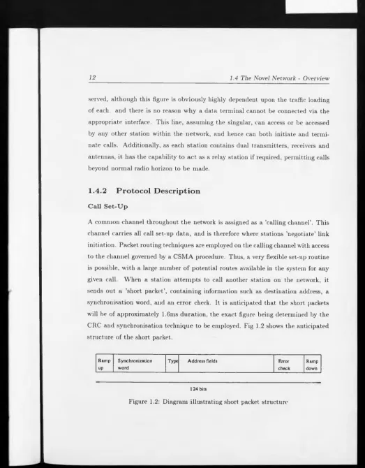
given call. When a station attempts to call another station on the network, it
sends out a ’short packet’, containing information such as destination address, a
synchronisation word, and an error check. It is anticipated that the short packets
will be o f approximately 1.6ms duration, the exact figure being determined by the
CRC and synchronisation technique to be employed. Fig 1.2 shows the anticipated
structure o f the short packet.
Ramp Synchronization Typ« Address fields Error Ramp
up word check down
124 bits
[image:27.551.12.535.8.678.2]13 1.4 The Novel Network - Overview
This is received by all stations within range which are in receive mode on the
calling channel, examined and re-transmitted if necessary (i.e. if the station which
received the packet is not the destination station, then it will re-transmit the packet),
the process continuing until the destination is reached. Call set-up then continues,
involving both terminal stations and the appropriate relays, by the exchange o f
’short packets’ o f the same form as that initiating the whole process, but containing
frequency allocation information, terminal state information (engaged, free etc), and
other necessary set-up data. This process takes place in an asynchronous manner.
O nce the set-up procedure has been completed, a link has been established, possibly
over a number o f channels if relays are involved, and the actual users’ information
can be transmitted.
An important point which arises from the possible reduction in baseband data
rate due to a change o f CODEC is that if the set-up procedure on the calling channel
proceeds at the reduced rate then the time taken for call set-up, and therefore
congestion on this frequency, will increase proportionally. The importance o f this
effect will obviously need appropriate consideration.
S p e e c h M o d e O p e ra tio n
O nce the call set-up is complete, the users’ speech can begin to be sent. Circuit-
switched techniques are now employed, This will be sent by burst-mode (TD D )
transmission o f speech digitised into a 32 kbit/s format (or less, as mentioned previ
ously). The actual data rate o f the speech information at the transmitter will be in
the order of 80 kbit/s, since burst mode operation will double the initial rate, and
the requirement o f ’guard bands’ between bursts implies a further increase in rate,
so it is anticipated that 80 kbit/s will be the overall rate. Data is actually to be
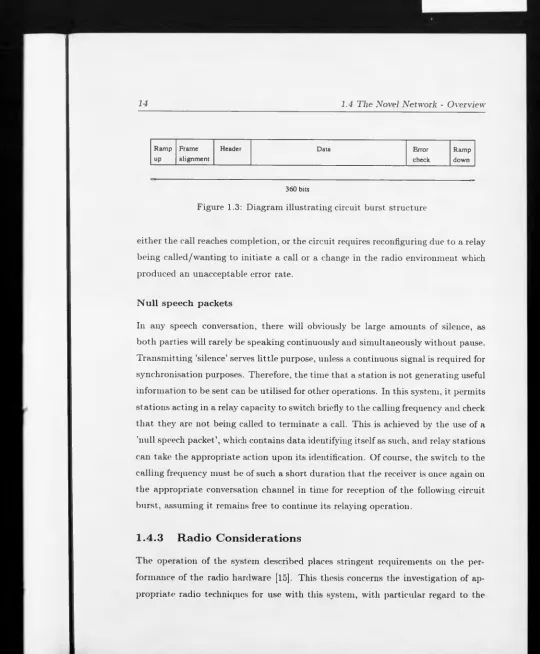
sent in 5 ms frames, each frame being termed a ’circuit burst’ , or a ’speech packet’ .
W ithin that frame will be a 0.5 ms guard band, therefore the actual duration of a
circuit burst is 4.5ms. Fig 1.3 shows the structure of a circuit burst.
14 1.4 The Novel Network - Overview
Ramp Frame Header Data Error Ramp
up alignment check down
360 bits
Figure 1.3: Diagram illustrating circuit burst structure
either the call reaches completion, or the circuit requires reconfiguring due to a relay
being called/wanting to initiate a call or a change in the radio environment which
produced an unacceptable error rate.
N u ll s p e e ch p ackets
In any speech conversation, there will obviously be large amounts o f silence, as
both parties will rarely be speaking continuously and simultaneously without pause.
Transmitting ’silence’ serves little purpose, unless a continuous signal is required for
synchronisation purposes. Therefore, the time that a station is not generating useful
information to be sent can be utilised for other operations. In this system, it permits
stations acting in a relay capacity to switch briefly to the calling frequency and check
that they are not being called to terminate a call. This is achieved by the use o f a
’null speech packet’ , which contains data identifying itself as such, and relay stations
can take the appropriate action upon its identification. O f course, the switch to the
calling frequency must be of such a short duration that the receiver is once again on
the appropriate conversation channel in time for reception o f the following circuit
burst, assuming it remains free to continue its relaying operation.
1.4.3
Radio Considerations
The operation o f the system described places stringent requirements on the per
formance o f the radio hardware [15]. This thesis concerns the investigation o f ap
[image:29.555.1.541.14.668.2]15 1.4 The Novel Network - Overview
propagation and modulation aspects.
S p e ctru m
It is anticipated that around 200 channels would be required to serve a large area
reliably, with relatively low densities o f telephones. This relatively large number
o f channels will necessitate wide frequency allocation, and obviously the more the
bandwidth o f the individual channels can be reduced then the less the total sys
tem bandwidth required. Whilst VHF/UHF radio spectrum may not be congested
in many developing countries, and therefore a large frequency allocation may be
granted by regulatory bodies, this may not always be the case, and indeed the situ
ation will be likely to change in future years. Therefore it is of major importance to
keep the overall spectrum required to a minimum for a given system performance.
Additionally, the bandwidth of the system places the requirement that radio hard
ware (antennas, power amplifiers etc) must operate satisfactorily over quite a large
frequency range. Traditional analogue radio systems employing FM modulation
use a channel spacing o f either 12.5 or 25 kHz, however this is now only really be
coming practicable in digital systems with recent advances in CODEC techniques,
and work on efficient modulation techniques (high-capacity microwave systems are
not considered here due to very different nature and application o f such systems).
Power limitations dictate the use o f modulation schemes which can perform well
at relatively low signal-to-noise ratios ( less than 20dB), which rules out the most
efficient high-level schemes. A spectral efficiency o f 1 bit/sec/H z (bps/H z), a figure
which digital cellular radio systems improve upon by only 10-20 %, would imply an
overall system bandwidth o f 16 MHz, assuming 200 channels and 80 kbit/sec trans
mission. This represents a significant percentage bandwidth (bandwidth/operating
frequency) at VHF frequencies. If the spectral efficiency could be increased to 2
bps/H z, however, the bandwidth and hence percentage bandwidth o f the system
16 1.4 The Novel Network - Overview
R e q u ire m e n ts o f B u rs t-m o d e O p e ra tio n
More detailed consideration of this issue will be given later, however, a general
description o f the basic problems arising due to this operation is given here. Burst
m ode operation requires that the transmitter(s) should be turned on and off at a
fairly high rate. This has implications for the transmitter circuitry, and for the
actual spectrum o f the radio signal produced.
Within the transmitter, circuits must have very short time-constants to ensure
that switch o n /o ff can be achieved in a short time, and to limit this time to several
microseconds means that very careful circuit design must be followed. Standard
circuits must be modified as, for example, typical decoupling circuitry would be
unacceptable due to the large capacitances associated.
The frequency spectrum of a burst-mode signal may be found to be inferior to
that o f a signal in continuous transmission. This spectral spreading effect is due
to the o n /o ff transitions o f the RF waveform, and therefore remedial measures are
generally necessary if the switching is at a significant frequency. ’Ramping’ up
and down o f the transmitted signal will be beneficial in this respect, as the harsh
transients are avoided. It is insufficient, however to consider only the amplitude o f
the transmitted signal if ramping is used, as phase continuity is important also in
minimising any spectral regeneration.
R a d io P r o p a g a tio n
Ideally, any transmitted signal will arrive at a receiver a short time later without
distortion and interference, and will be o f sufficient signal strength to ensure reliable
detection, hence providing perfect reception o f the transmitted speech, or data, at
the receiver output. Unfortunately, the radio environment is rarely so kind, and the
receiver will need to recover the signal, perhaps distorted, from a certain amount o f
noise and interference.
17 1.4 The Novel Network - Overview
a substantial transmission loss, limiting the signal at the receiver to a very low
level. Additionally, smearing o f the signal in time may occur due to multipath
effects, such as reflections from hills. This spreading in time can lead to inter
symbol interference, ISI, in digital systems, which is very likely to produce errors at
the receiver. Normal point-to-point radio systems will have to operate over a given
path reliably, which, if the path is poor, may necessitate large power levels and good
antennas. In this system, however, there is the great advantage that a particularly
useful form o f diversity, route diversity, is inherent, and will permit a call to be
made over a number of paths, some o f which will obviously be much better than
others. The call set-up procedure will dictate that the overall path being used will
be adequate for transmission, and if, for any reason, the path should deteriorate,
then reconfiguration of the route will permit the call to continue without ’dropping
out’ , as would be the case with most other systems.
The system, being considered primarily to be a network o f fixed nodes, has nu
merous advantages over m obile/portable networks, which are receiving much atten
tion at present, from a propagation point of view. In the mobile situation, extremely
fast fading of the transmitted signal will occur due to the motion o f the vehicles,
and the radio path effectively changing dramatically from one instant to another.
Receivers must be able to cope with fade rates in the order of kilohertz, and with
depths exceeding 30 dB. In addition, doppler shift will occur due to the motion,
which will cause additional problems with the detection process. One end of a mo
bile link will typically have a very low, and perhaps inefficient, antenna, which will
cause path losses to be large, and prevent true line o f sight propagation for much of
the time. Range will therefore be very limited. In the fixed environment, however,
things are somewhat simpler, as propagation conditions will be substantially more
stable, as any fading of signals will tend to be very slow, and due solely to changing
atmospherics. Hence, short range links are unlikely to show significant rapid changes
with time. Since stations are fixed, and permanent, antennas will be at good heights
18 1.4 The Novel Network - Overview
far greater than in the mobile environment, as path losses will be much reduced.
Since propagation data is very rare for developing countries, it was decided that
it would be very useful to produce some typical figures for paths likely to be found
where the system will find implementation. A period o f time was spent in Sierra
Leone, West Africa, characterizing a number o f typical channels in different areas,
and this work is detailed in Chapters 2 and 3. Sierra Leone offers a wide variety
o f terrain types, and a climate typical o f tropical Africa, and hence was considered
to be a suitable country for the field work. Measurements o f transmission loss and
time delay spread were made.
P o w e r R eq u irem en ts
Due to the fact that most o f the stations in a network will be powered from a solar
panel which charges a battery, power consumption is an important factor. Therefore,
the station hardware should be power efficient. The transmitter power amplifier will
be the major factor in this respect, and hence it must dissipate as little power as is
practical. For this reason, it was considered worthy of some detailed research, which
formed a major part of this work.
Traditional power amplifiers fall into two main categories; linear amplifiers, class
A, B and AB, are used for amplifying signal o f varying envelopes, and tend to be
very p oor with regard to power efficiency, and non-linear amplifiers, typically class
C, which are for amplifying constant envelope signals and are much more efficient.
Obviously, therefore, it would be desirable to use a non-linear PA, for reasons o f
power efficiency. However, it is the case that the most spectrally efficient modu
lation schemes are those which are linear, and hence a linear PA must be used to
preserve the spectrum. A method o f linearising a non-linear PA has been investi
gated, which, when combined with an efficient modulation scheme, can perform well
in both respects.
Chapters 4, 5, 6 and 7 detail the work performed in the area o f modulation,
19 1.4 The Novel Network - Overview
Chapter 4 explains the choice o f modulation scheme, which is 7t/ 4 -DQPSK, and
describes how this scheme is particularly suitable for the system. Filtering o f the
signal is considered in some detail, with regard to the choice o f a transmit filter
which produces a good signal spectrally, with a practical implementation technique,
and which will combine with a similar filter in the receiver to minimise ISI. Chapter
5 then describes the implementation o f a tt/ 4 -DQPSK modulator using EPROM
look-up techniques and Nyquist filtering. Chapter 6 details the concepts behind, and
implementation o f the RF stages o f a linearized transmitter which is both power and
spectrum efficient. Chapter 7 details the work done on the distortion analysis of the
modulated power amplifier stage. Intermodulation distortion (spectral spreading)
o f the transmit signal produces adjacent channel interference, and hence is of great
importance. By characterizing the distortion characteristics o f the stage, it is possi
ble to accurately predict the resulting spectral spreading. Conclusions o f the work
Chapter 2
Propagation Background and
Measurement Results
21 2.1 Radio Propagation
2 . 1
Radio Propagation
In any radio system, the success rate o f transmission of information from one point to
another will depend very heavily upon the actual propagation o f the signal between
the two. Certainly, it is necessary to have some knowledge o f the radio environment
in which any system will operate to give the designer the information required to
determine such parameters as the transmitter power needed to reduce information
loss to an acceptable level, antennas necessary, and receiver specifications. There
are several mechanisms by which radio waves may propagate, however these are
generally both frequency and distance dependent modes. Consequently, for a given
frequency o f radio wave there will tend to be one dominant method for a particular
propagation distance. For ’line-of-sight’ radio links, such as those which are under
consideration in the project with which this work is associated, frequencies in the
VHF, UHF and microwave range are typically employed, the exact frequency de
pending upon the application and the actual segment o f radio spectrum allocated by
the relevant regulatory body. High capacity systems must use microwave frequencies
because o f signal bandwidth, whereas low capacity systems will normally operate in
the VHF or low UHF areas, primarily for reasons o f signal bandwidth. There are
advantages to operating at the lower frequencies, however, and these include better
penetration o f signals into valleys, less critical antennas, and lower feeder losses
2.1.1
V H F /U H F Propagation
‘Ground wave’ propagation is the most important mode for line-of-sight VHF/U HF
links. Ground wave propagation actually divides into two main mechanisms [53]:
a) surface wave propagation is where wave energy travels along the earth’s sur
face, however the attenuation involved increases with frequency since the conduc
tivity o f the earth decreases, with the result that propagation at VHF and above
is particularly hindered. In the VHF range (30 to 300 MHz), the surface wave is
22 2.1 Radio Propagation
above 300 MHz [25].
b) space wave propagation involves the wave energy propagating through the
troposphere, a region extending to approximately ten miles above the earth’s surface,
from transmitter to receiver. This is the primary mode for line- of-sight VHF/UHF,
and when a relatively unobstructed path is used with antennas at good height the
surface wave signal will typically be insignificant in comparison.
Space wave propagation can result in several signals arriving at a receiver, from
a single transmitter. This occurs due to a direct wave arriving together with signals,
from either ground reflections or ‘reflections’ due to a refraction process within the
troposphere. Any combination o f these signals may arrive at the receiver, depending
upon the local terrain and atmospheric conditions. The effects o f such multipath
propagation are detailed in the later section.
F re e -S p a ce Transm ission Loss
A useful starting point in the consideration o f a point to point radio link is the free-
space transmission loss; this is the loss which would occur were the path between
the transmitter and receiver a straight line in a vacuum or ideal atmosphere, and
unaffected by absorption or reflection resulting from any objects. Isotropic antennas
are assumed, however the antenna aperture is assume to decrease directly with
frequency. Quantitatively, this loss, A a, can be determined by:
A „ = 20 log10 —— dB = 32.5 -I- 20 log10 / (MHz) + 201og10d (km) dB (2.1) A
where d is the distance between transmitter and receiver, / is the carrier fre
quency and A its wavelength.
O f course, in any practical system the actual loss is likely to differ significantly
from this figure, due primarily to obstructions, reflections, absorption and non-
23 2.1 Radio Propagation
not straight-forward, however, due to the various mechanisms involved (diffraction,
refraction and reflection primarily). Examination o f a path profile will, however,
illustrate the general propagation situation and an approximate calculation can be
performed based upon equations for free-space loss, diffraction loss, ground clearance
and so on.
D iffra ctio n
General line-of-sight system design will strive to ensure that transmit and receive
antennas are in the clear, and no obstructions lie between, hence providing a direct
signal o f suitable strength. However, in some situations this is not possible, as will
often be the case where transmitters are located in villages distributed around a non
flat region, and paths may be required between them all, regardless of terrain. If the
terrain between the transmitter and receiver is rough, possibly with obstructions,
propagation is still possible as a result of diffraction. Diffraction is the bending
o f waves around objects. The bending decreases with increasing thickness o f the
obstruction and frequency of the radio wave. Thus, particularly in the VHF region,
usable signal levels may be present at a receiver despite an obstruction in a path,
such as a low hill. Additionally, it enables propagation beyond normal line-of-sight,
allowing for the curvature of the earth, by diffraction around the horizon, albeit
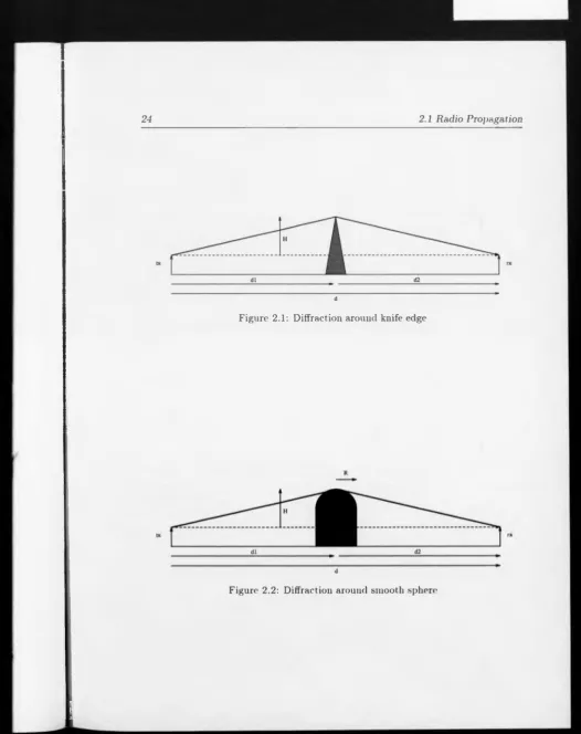
with a certain degree o f signal attenuation. The two extreme cases o f diffraction
are those o f diffraction over a smooth sphere and over a knife-edge. For a given
obstruction height, the loss due to knife-edge diffraction will be considerably lower
than that due to smooth sphere diffraction. The above two diffraction situations
are shown in figs 2.1 and 2.2.
If the height o f the obstruction is decreased until grazing incidence occurs, a
loss still occurs, which in the case o f perfect knife-edge diffraction is 6 dB, and for
a smooth-sphere is 20 dB [46, 53]. It is not until a certain clearance is obtained
that a figure approaching the free- space value is found to occur. Commonly, the
24 2.1 Radio Propagation
Figure 2.1: Diffraction around knife edge
[image:39.559.13.540.10.675.2]25 2.1 Radio Propagation
in terms o f Fresnel zones, where the nth Fresnel zone is that boundary o f points
from which a wave could be reflected with a path difference of n half wavelengths
to the direct signal when incident at the receiver. Using this concept, it is found
in practice that for minimal diffraction loss to occur over a link there should be no
obstacles within about half the clearance o f the first Fresnel zone [25]. On medium
to long range UHF or microwave links additional clearance may be required under
certain atmospheric conditions due to refraction (see next section).
Basic equations are given in [52] for the calculation of diffraction loss around a
knife edge: as a starting point a parameter v is defined as
where h is the height o f the obstacle above the direct line between transmitter
and receiver, d 1 and (12 are the distances between the edge and either end of the
link.
/
Boundary of first Fresnel zone
Tx Rx
Figure 2.3: Diagram illustrating first Fresnel zone
(2.2)
and then the actual loss, L (u) is given (for u > —.5) by
L(u) = 6.4 + 2 0 log10((t/ + 1 )j + u) dB (2.3)
[image:40.556.18.542.14.705.2]26 2.1 Radio Propagation
ceiver normally well beyond the mutual radio horizon can permit reliable transmis
sion o f a signal over distances much greater than those possible over flat ground, and
this effect has been referred to as ‘obstacle gain’ . As an example, it was reported
[43] that a transmission loss o f only 134 dB was found on link operating over 160
miles via diffraction over an 8000 ft mountain in Alaska. Such effects are obviously
o f primary importance where systems must operate in mountainous regions, as the
potential for both reliable transmission and interference will exist.
In hilly regions many non LOS paths will be dependent upon diffraction around
more than one obstacle. In this case, the method used to calculate the total diffrac
tion loss is not obvious, and several techniques have been proposed [44].
O f these, the two which are most widely referred to are illustrated in fig 2.4
The upper figure in the diagram shows the technique attributed to Epstein and
Peterson [51]. Each obstruction in the path is treated with equal importance, and as
a source/sink if the transmitter/receiver are obstructed when diffraction losses are
calculated for adjacent ridges. In the diagram, the first loss occurs around the first
(highest) ridge. This loss is calculated by taking the distances to the source/sink
as d l and d2, respectively, and the height o f the ridge as h i, the difference between
the peak o f the ridge and what would be the line-of-sight path between transmitter
and second ridge. The loss around the second peak is calculated from the values
d2, d3 and h2. The total loss is simply the sum o f these diffraction losses and the
free-space loss for the path between the transmitter and receiver.
The lower diagram shows the technique which was proposed by Deygout [50].
Initially, the case o f two hills is used, however this situation can be extended to in
clude any number o f hills, albeit with additional computation over the other method
above. In the case o f two hills, one o f these is defined as the main hill; this is done
by calculating which hill has the highest h/r figure, i.e. greatest obstruction o f first
Fresnel zone. The diffraction loss around the main hill is calculated using the total
distances between the hill and the transmitter/receiver, and the height o f the hill
27 2.1 Radio Propagation
case. In the diagram the appropriate distance used in the calculation are d 1, d2 + d3
and h i. The loss around the other hill is then calculated by taking the distances
between adjacent main hill and transmitter or receiver, assuming adjacency to one
or other. Therefore, the values used here are d2, d3 and h2. If there are more than
two obstructions, then the matter is made slightly more complex by the systematic
repetition o f the process used for two hills. That is, further groups of hills are split
into normal/main importance. The process repeats until there are no two adjacent
’normal’ hills.
This technique therefore differs from the previous one in that importance is
attached to hills in a hierarchical manner. The actual results obtained are often
very similar for the two, but can occasionally differ by up to around 10 dB [44]
for certain types o f profile. Since the diffraction loss figure for the main hill in the
Deygout method is always greater than that which would be calculated in the first
method, the former always predicts a greater path loss. Over the majority o f paths,
the small difference in the results (typicall less than 5dB) o f the two techniques do
not justify the extra calculation involved in Deygout’s technique, and the Epstein-
Peterson method is sufficient.
Obviously, the assumption that ideal knife-edge diffraction occurs is inaccurate
for many cases, and, additionally, account is rarely taken o f the transversal profile
o f the terrain at the diffracting edge, which can give rise to significant errors [52].
Accurate prediction of ground reflections is very difficult [46], and this adds further
potential errors to the procedure. Therefore, the accuracy o f path loss calculations
is often only an approximate procedure, and, in general, an error in the order of
5 dB is to be expected, but may be considered sufficiently accurate for almost all
purposes.
R e fr a c tio n
Refraction, mentioned previously, also produces bending o f the radio wave due to
28 2.1 Radio Propagation
d2
d3
[image:43.557.18.540.8.683.2]29 2.1 Radio Propagation
under normal atmospheric conditions, is that the radio horizon is further than the
physical horizon. This results form the fact that the refractive index o f the atmo
sphere generally decreases with altitude, causing velocity of radio transmission to
increase with height, and therefore a curving towards the earth of the radio signal,
hence extending the apparent horizon. If the change in refractive index is linear
with height, then the result is that the radio signal apparently travels in a straight
line over an earth with modified radius
where a is the true radius o f the earth, and dn/dh is the rate o f change of
refractive index with height.
A com m on value accepted for k is 4 /3 , which results from a decrease o f refractive
index with height o f approximately 3.9 * 10-8 per metre.
However, as dn/dh varies so the effect on the propagation of the radio signal
can vary significantly. Under certain conditions the refractive index may actually
increase with height (for a reasonable height ), with the result that the signal will
bend away from the earth. Conversely, as the rate o f change increases above the
normal value, so the effective bending o f the signal back to earth will increase. For
a factor o f four increase, the earth appears flat since propagation will occur parallel
to the earths surface. Above this rate, signals may be bent back down to earth
to be reflected form the surface, and subsequently bent back down and reflected
again, with the process continuing indefinitely while the atmospheric conditions
remain similar. This effect is known as ducting, as the signal propagates in a duct
between the earths surface and the upper level of the radio path. Ducting can cause
propagation o f signals over distances many times those encountered under normal
conditions, with obvious possibilities for interference to other users of the frequency
employed. An elevated duct occurs when the signal is effectively trapped within a