Characterising the Ripple Effects of
Introducing Energy-Awareness Functionality
in Cyber-Physical-Systems Software
MASTER THESIS
A. (Atze) Bouius CSC-MS-SE - Software Engineering
Committee: prof.dr.ir. Mehmet Ak¸sit dr. Pim van den Broek dr.ir. Jan Broenink dr. Somayeh Malakuti prof.dr. Valter Vieira de Camargo
January, 2015
Abstract
This research investigates what impact energy-awareness functionality has on an existing soft-ware design. Energy-asoft-wareness has become increasingly important in softsoft-ware development; especially for Cyber-Physical Systems. Nowadays society is more conscious about energy con-sumption; optimising energy usage has become an important selling point. Self-adaptation of system behaviour can heavily influence energy usage; especially for battery powered systems. Information about power consumption can be used to plan ahead; the system can try to react and adapt before it runs out of power. A lot of existing software systems have no notion of energy; the introduction of energy to an existing system may result in side effects. These effects or ripples are modifications that are caused when energy-awareness functionality is added to the existing system. Energy-awareness functionality has a crosscutting nature; it is present through-out the system from hardware driver to high level planning and adaptation components. This may result in an implementation where this functionality is scattered and tangled with multiple components; every component may contain statements concerning energy consumption.
To investigate the effects of introducing energy-awareness functionality to an existing design, we conduct a case study. Initially we designed a base design which is energy unaware. However, best efforts are made to prepare the design for future evolution. The base design is split into two parts: the base system and the control system. The control system adapts the behaviour of the base system. The initial design was composed of various design patterns. The Observer pattern and Visitor pattern served as interfaces for the control system to the base system. The control system follows the MAPE-K terminology which is commonly used to describe control loops. The control system contains a state space (State pattern) to determine the most suitable adaptation. A domain analysis is conducted to extract energy evolution scenarios. The energy-awareness functionality introduced by these scenarios is added to the base design. We observed the design ripples that occurred after implementation of the functionality by various techniques; an object oriented (OO) and an aspect oriented (AO) design are evaluated. Both designs are evaluated using various basic metrics (lines of code (LOC), number of components and operations). To observe the diffusion of a concern over a design we use concern diffusion metrics. A scenario-based analysis technique SAAM is applied to show evolution impact for each separate evolution scenario.
re-Contents
1 Introduction 2
1.1 Research Questions . . . 2
1.2 Related Work . . . 2
1.3 Proposed Solution . . . 5
1.4 Thesis Outline . . . 6
2 Background 8 2.1 Cyber-Physical Systems . . . 8
2.2 Energy . . . 9
2.3 System Control . . . 10
2.3.1 Physical Control . . . 10
2.3.2 Software Control . . . 11
2.4 Software Evolution . . . 13
2.4.1 Scenarios . . . 14
2.4.2 Modularity . . . 15
2.4.3 Crosscutting Concerns . . . 16
2.4.4 Modularising Energy . . . 16
2.4.5 Metrics . . . 17
3 Cyber Physical System Case Study: Patrol Robot 19 3.1 Application Scenario . . . 19
3.2 Requirements . . . 19
3.3 Initial Design Of The Robot . . . 21
3.3.1 Design Alternatives . . . 21
3.3.2 Design Choices . . . 24
3.3.3 Initial Design . . . 25
4 Energy-aware Robot Design 33 4.1 Domain Analysis . . . 33
4.2 Scenarios . . . 34
4.3 Evolution Impact on OO Implementation . . . 38
4.3.1 Initial Control System Architecture . . . 38
4.3.2 Base-scenario Implementation . . . 40
4.3.3 Energy-awareness Evolution Impact . . . 40
4.4 Evolution Impact on AO Implementation . . . 46
4.4.1 AO Improvements Initial Control System Design . . . 46
4.4.2 Base-scenario Implementation . . . 54
4.4.3 Energy-awareness Evolution Impact . . . 56
5.2 Results . . . 60
5.2.1 The Impact of Energy-awareness Functionality to the OO Design . 60 5.2.2 The Impact of Energy-awareness Functionality to the AO Design . 63 5.3 Evaluation . . . 66
5.3.1 Comparison . . . 67
5.3.2 Interpretation and Discussion . . . 69
5.3.3 Conclusion . . . 70
6 Beyond Objects 71 6.1 Existing Event-Based Modularisation Techniques . . . 71
6.2 Esper . . . 72
6.2.1 Overview . . . 72
6.2.2 Applicability Case Study . . . 73
6.2.3 Conclusion . . . 75
6.3 EventReactor . . . 75
6.3.1 Overview . . . 76
6.3.2 Event Reactor MAPE-K Implementation . . . 77
6.3.3 Applicability Case Study . . . 79
6.3.4 Conclusion . . . 81
6.4 Conclusion . . . 82
1 Introduction
Energy-awareness has become increasingly important in software development; especially for Cyber-Physical Systems (CPS). Society has become more conscious about energy consumption and optimisation of energy usage has become an important selling point. Self-adaptation of system behaviour can heavily influence energy usage; especially for battery powered systems. Battery-powered systems deal with a limited power supply and need to save resources to be able to complete their tasks. The information about power consumption can be used to plan ahead, the system should try to react and adapt before it runs out of power. Running out of power in the middle of a task can be undesired; especially if the task cannot be resumed if the system restarts. A lot of existing software systems have no notion of energy. The introduction of energy-awareness functionality to an existing system may result in side effects. These effects or ripples are modifications that are needed to add the energy-awareness functionality to the existing system. This may reveal flaws in the design or break down the design entirely. Therefore, modularisation of this functionality will be a difficult task; energy-related code fragments might be scattered throughout the entire code. Energy-awareness functionality has a crosscutting nature; it is present throughout the system from hardware driver to high-level planning and adaptation components. This may result in an implementation where this functionality is scattered and tangled with multiple components; every component may have statements concerning energy consumption.
1.1 Research Questions
Software evolution is a challenging topic, designers must take into consideration what will happen if a new concern is introduced. The introduction of an unexpected concern may break down the design completely. The question will rise if this is the fault of the design or if it could have been prevented by taking different design choices. We will investigate the introduction of energy-awareness functionality to Cyber-Physical Systems. The following research questions are formulated:
• What are the effects on software modularity that follow from the introduction of the energy concern to Cyber-Physical Systems?
• Can the energy-awareness concern be introduced to an existing Cyber-Physical System without crosscutting existing concerns?
Answers to these questions should give insight in the effects that follow with the introduction of energy-awareness functionality to an existing software system.
1.2 Related Work
De Lemos et al. (2013) [1] propose a roadmap for developing, deploying, managing and evolution of self-adaptive software systems. Specifically, they focus on development methods, techniques, and tools that they believe are required when dealing with software-intensive systems that are self-adaptive in their nature. The research identifies four ma-jor topics crucial for engineering self-adaptive software systems: design space, software engineering processes, centralised to decentralised control, and practical run-time verifi-cation and validation (V&V). Especially the decentralisation of control loops which form the control system is interesting for this research. They use the MAPE-K [2, 3] termi-nology and present the following patterns: Hierarchical Control, Master/Slave, Regional Planner, Fully Decentralised and Information Sharing.
The following research challenges are formulated: the identification of what circum-stances that decide the applicability of patterns, as well as which application domains or architectural styles are better managed by patterns. Another major challenge is to identify techniques that can be used for guaranteeing system-wide quality goals, and the coordination schemes that enable guaranteeing these qualities. The focus of their research is on the control system itself; instead of our research which focus is on the coupling between the base system and control system. Their research is presented as a roadmap for CPS development; instead of our research in which we conduct a case study to find out if our assumptions of energy-awareness being a crosscutting concern is valid. Te Brinke et al. (2013) [4] present a method for developing energy-aware software. In green software development the reduction of overall energy consumption of the software is an important issue. This can be achieved by energy optimisers; software can be made energy-aware by extending its functionality with energy optimisers. Energy optimisers monitor the energy consumption of software and adapt it accordingly. Energy is consid-ered as a special kind of resource; a component may consume various resources, which eventually may lead to the consumption of energy.
A method is proposed to design energy-aware software systems in such a way that modularity is achieved in the design of such systems. Key steps in this method are the identification of components, modelling of ports (interfaces), the modelling of resource behaviour, analysis and finally the selection of most suitable optimiser component. They illustrate the usefulness of their technique in a separate technical report where they apply the method to a media player case study.
The main focus of this research is on model checking where our study presents a complete implementation for a robotic system. Although the media player is also some kind of CPS it does have access to a fixed power supply; the robot instead deals with a limited power supply and needs more complex energy-awareness adaptation scenarios to ensure maximal operation time and performance.
strategies.”
Their work focuses on finer-grained programming language-level solutions for CPS de-velopment. Three main linguistic approaches are analysed: meta-programming, aspect-oriented programming (AOP) and context-aspect-oriented programming (COP). Each approach is analysed and compared on the following topics: application, behavioural change, mon-itoring and finally variations and separation. The following research challenges were formulated: modularisation, extensibility, performance impact, adaption to unforeseen situations and impact on the development process.
The paradigms discussed in this article solve the problem of extending existing (main-stream) languages with the flexibility required by self-adaptive systems. AOP, COP, and meta-programming introduce new directions of variability to model behavioural adapta-tion; they support interception to inject monitoring code, and the dynamic modification of normal execution. They conclude that it is hard to provide conclusive arguments for the benefits they achieve through the use of specific linguistic support. Empirical obser-vation should be conducted on application development to be able to provide conclusive arguments; our research may help to provide these arguments. Our research illustrates that CPS development can profit from applying AO programming. The AO implemen-tation of our design reduced the impact of energy-awareness evolution scenarios to the existing design drastically. Existing components can be extended by aspects instead of modified.
McKinley, Sadjadi, Kasten and Cheng (2004) [6] conduct a survey about approaches that have been proposed for building software that can dynamically adapt to its environ-ment (self-adaptive systems). Adaptations do not only involve changes in program flow, but also run-time recomposition of the software itself. When designing self-adapting systems three key technologies should be considered: separation of concerns, compu-tational reflection, and component-based design. Together, they provide programmers with the tools to construct self-adaptive systems in a systematic and fundamental way. In addition they discuss how middleware supports compositional adaptation. Middle-ware effectively provides a level of indirection and transparency that can be exploited to implement adaptations.
They list a number of research projects and commercial software packages that sup-port some form of compositional adaptation, and conduct a taxonomy that distinguishes approaches by how, when, and where software composition takes place in these projects. They identify the following key challenges: assurance, security, interoperability, and de-cision making. They conclude that compositional adaptation is very powerful; however, without appropriate tools to automate the generation and verification of code, it may have a negative impact on the integrity and security of systems, instead of improving it. Unlike our research they focus on analysing software composition in existing commer-cial software packages; our research instead focusses on the application of commercommer-cial software packages with respect to energy-awareness evolution.
role of computational reflection in the context of self-adaptive software systems. Reflec-tion is about meta-computaReflec-tion, i.e., computaReflec-tion about computaReflec-tion. They identify several reflection properties and group them in a reflection prism with three sides: Self-Representation, Reflective Computation and Separation of Concerns.
Any computational system has a domain model, which corresponds to the type of the application domain (business problem) addressed by the system. In a reflective system, there is a distinction between the domain model and the self-representation. Self-representation is a key characteristic of any reflective software system. Self-Self-representation has four key properties namely: type of representation, granularity, uniformity and com-pleteness.
The reasons for using reflection in a system vary; the behavioural properties of a re-flective system affect several system properties. Together these properties make up the reflective computation side of the prism. Properties here are: type of reflection, causal-ity, level-shifts and frequency of these shifts. In the context of reflective computation, separation of concerns is vital as the reflective behaviour increases the systems overall complexity.
If the reflective system is able to support separate models of different system aspects, possibly at different reflective levels, the overall complexity can be reduced. Proper-ties here are: disciplined split, transparency, hierarchy and extensibility. They apply the properties of the reflective prism to different case studies and identify key chal-lenges when building self-adaptive systems. These chalchal-lenges lie in expressiveness of self-representation, meta-level conflicts, uncertainty, autonomy and transparency. In this research we apply the self-representation side of the reflection prism by conducting a domain analysis, from which we extracted an environment model for the system. Our system needs the environment model to be able to navigate and move around.
1.3 Proposed Solution
In order to investigate the effects of introducing energy-awareness functionality to an existing software design we will follow this roadmap:
• Define a initial energy-unaware robot software design.
• Introduce energy-awareness functionality through evolution scenarios.
• Implement energy-awareness functionality in established techniques (OO and AO programming).
• Experiment by conducting measurements on the OO and AO implementations. • Evaluate how established and experimental event-based modularisation techniques
can help to solve the exposed problems.
prepare the design for every possible evolution scenario. The patterns that we adopted for implementing energy-awareness functionality via control loops are Observer, Visitor and State pattern. The system can be made self-adaptive by adopting control-loops to implement high-level adaptation mechanisms. Together control loops form the control system; the control system is coupled to the base system by the Observer and Visitor pattern.
The impact of energy-awareness evolution is illustrated by a case study: a security robot patrolling an environment. The robot must adapt its behaviour depending on its position in the environment and security threats. A domain analysis is conducted to extract energy-awareness evolution scenarios. The energy-awareness functionality introduced by the scenarios is added to the existing design adopting OO and AO pro-gramming.
The OO model has many shortcomings, crosscutting concerns are hard to implement in the object model. A concern is crosscutting if its implementation is scattered and tangled within many components. The extension of fixed interfaces results in ripples throughout all classes implementing these interfaces. Adding new functionality leads to rewriting or adding new methods to existing classes. Dynamic class extension as well as the dynamic interface declaration mechanisms provided by AO, solve many of these problems. However, state space evolution and especially the introduction of new states cannot be solved by aspects. Context-dependent state information prevents aspects from isolating the state-context concern. Extension of each context is context dependent which makes it impossible to generalise it into a reusable concern.
This research will compare OO and AO implementation using various modularity met-rics and scenario-based analysis. Experimental event-based modularisation techniques will be evaluated to see if a higher degree of decoupling and modularity can be achieved. Since some of these techniques are still in development and only partially implemented we cannot conduct measurements on it. However these experimental techniques will give an insight in the (future) possibilities for modularising and decoupling energy-awareness functionality from an existing design.
1.4 Thesis Outline
This research gives insight how the introduction of the energy-awareness concern to an existing CPS affects the modularity of the design. In chapter 2 some background information about CPS, control systems, energy, software evolution, modularity and metrics is provided.
A case study is conducted to illustrate how an existing design is affected by the introduction of the energy concern. Various techniques are applied and evaluated to minimise evolution impact on the design.
Inchapter 3we will present the case study scenario and the respective requirements and assumptions who have to be considered for the initial design. Further this chapter gives an overview of the various design alternatives and design choices for the initial design.
requirements through energy evolution scenarios. The scenarios are extracted from the conducted domain analysis. OO and AO implementations are presented; both imple-mentations implement the energy evolution scenarios.
In chapter 5 we will present the evaluation method. Metrics are calculated for both implementations and the results are compared. An overview of the applicability of event-based modularisation techniques is given in chapter 6. Esper and EventReactor are evaluated to determine how event-based modularisation can help to solve state space evolution problems.
2 Background
In this chapter we introduce Cyber-Physical Systems [8, 9] and provide background information to clarify the topic of CPS design. Typical CPS are closed-loop systems, they adapt behaviour according to feedback provided by sensors. These feedback loops are implemented by means of acontrol system. Some CPS like mobile systems deal with a limited energy supply. Energy-awareness functionality should be introduced to these systems to optimise their operation time. Energy management should be a self-adaptive process. Self-adaptive[2] software systems are typically implemented by the MAPE-K[2, 3] model. The key functions of self-adaptive control systems are: Monitor, Analyse, Plan and Execute over a common Knowledge base. Due to thecrosscutting[10] nature of energy-awareness functionality, we assume introducing energy-awareness functionality to an existing system may compromise themodularity of the design. We assume energy-awareness functionality is introduced by evolution scenarios. To evaluate the modularity of a design as well as the impact of evolution scenariosmetrics must be identified to be able to conduct measurements.
2.1 Cyber-Physical Systems
Cyber-Physical Systems [8, 9] are all around us, examples are traffic control and water resource management systems. Robotic systems also fall in the category of CPS.
– CPS systems are typically closed loop systems, where sensors make measurements of physical processes, the measurements are processed in the cyber subsystems, which then drive actuators that affect the physical processes –
[Edward A. Lee, UC Berkeley]
CPS form the bridge between the cyber world and the real world. More formally, they communicate with entities in the physical world and integrate computing with monitoring and/or control. They react to stimuli from the outside world and adapt their behaviour accordingly (emergent system behaviour) [8, 9].
Stimuli are triggers/events [8],eventsare occurrences/changes in properties of interest. To observe the real world, CPS make use of sensors. Sensors can observe a small part of the real world. Like distance to a wall, light intensity, battery power etc. Whenever such properties of interest change this is considered an event.
useless; for this reason events must be communicated in time.
CPS need to react to change continuously; the sequence of observing changes and adapting accordingly is a never ending loop. Usually feedback loops ensure adaptation to physical processes by the means of the computation of an advice/plan. This advice contains one or multiple adaptations that correct/adapt the system.
Developing CPS is a challenging task [9]; software component technologies like object oriented (OO) design and service-oriented architectures are based on abstraction that are intended for software rather than physical systems. The gap can partially be closed [9] with:
• advancements in formal verification; • emulation and simulation techniques; • certification methods;
• software engineering processes; • design patterns;
• component technologies.
2.2 Energy
The electrical point of view of energy [11] is: energy is absorbed by or generated from an electrical circuit. Energy is expressed by the following formula:
E(t) = Z t
0
P(τ)d(τ) (1)
Energy is power consumed over time, power can be defined as the amount of energy consumed per unit of time. Power is expressed by the following formula:
P(t) =V(t)∗I(t) (2) Power P at a certain moment in time is the product of the voltage V and current I at that moment in time.
2.3 System Control
Control systems are interdisciplinary; there exist physical control systems [12] as well as software control systems. Physical control systems, also called feedback or closed-loop systems, are used in mechatronics. Optimising machinery movements is an example of their application. These control systems can be implemented in either hardware or software and are applied in embedded systems. Software control on the other hand is implemented by feedback loops, keywords here are monitoring, analysing, planning and executing adaptations.
2.3.1 Physical Control
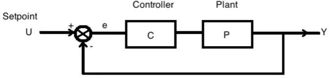
[image:13.595.128.468.338.418.2]Physical control realised by so-called control or closed-loop systems [12] work with a closed loop. The error in the output is fed back to the input in order to determine if additional correction is needed. Control systems provide a way to modify dynamic system behaviour through a feedback mechanism. A typical physical control system is modelled in a block diagram a general model is displayed in figure 1.
Figure 1: Physical control system
The preferred output value of the system is defined by theset-point orreference value. One must define a monitor to achieve this, the monitor compares the system output (Y) to the set-point value (U). The output of the monitor is called the error signal, the error signal (e) is the difference between the desired system output and the actual system output. The error signal is fed back as input to the system or plant to correct the output signal in order to decrease the gap between the actual output and desired output signal. The mathematical representation of the relation between the input and output can be expressed by a differential equation. This equation is called the system function or transfer function [12](p. 34-38). A control system can be turned into a closed-loop system if the output is measured before it is compared to the reference value. A non closed-loop system receives no feedback from the outside world.
2.3.2 Software Control
Software control is not limited to controlling a systems output, software control can model many complex feedback mechanisms. Software control systems are often referred to asself-adaptive systems. Complex systems with a wide variety of sensors and actuators can be modelled by various overlapping feedback [2] mechanisms. System behaviour optimisation is the main goal of software control; examples are controlling computation or request load for processor and server control systems. Another example would be an energy-management optimisation system.
Self-Adaptive Systems A lot of software systems must adapt to a changing environ-ment. A server system for example, which will get increasingly more requests and there-fore needs to deal with an increased workload. By detecting changes in the environment the system can predict what is going to happen and deal with it accordingly. In the example of the server system this could be the increment of the capacity. In this case, adding additional servers to a virtual machine can be a appropriate adaptation. This server system is an example of a self-adaptive system [2]. The adaptation functionality can be implemented as a feedback loop. A typical cycle would be: measure deviations (observe), comparison to a reference value (analyse), planning the best possible action (plan) and the adaptation to a changing environment (act).
Base System and Environment The base-system interacts with the outside world called the environment; the environment is the relevant part of the real world. The system interacts with the environment through sensors. Sensors measure certain chang-ing variables in the environment. These changchang-ing variables give the base system insight on what is happening in the environment. This information is crucial for self-adaption; without stimuli there is nothing to adapt to.
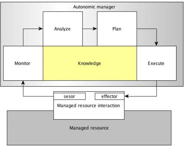
Figure 2: MAPE-K principle
We will briefly introduce the four control components as well as the knowledge base. The knowledge base can be accessed by multiple control loop components; however, it is in particular important to the analyser component. For this reason we will discuss the analyser and knowledge base together.
Monitor The monitor collects relevant information regarding the behaviour/structure of the base system (managed resource). Additionally it may collect information from the environment. Examples are: changing variable values and current state of the system. The base system and environment can be seen as subjects of the monitor. The monitor simply passes the data from the base system to the analyser. Therefore, it acts as an interface for the control loop to the base system. Complex systems that deal with many high rate data flows may have to deal with hardware limitations, e.g. insufficient memory and high CPU loads. In these cases data compression should be applied; average values can be used or some other correlations over a set of samples can be applied.
determine on an adequate action/adaption. The control system should plan how to adapt the base system.
Planner The planner component is closely related to the analyser; once the data is analysed there must be some coordination to adapt the base system. Analysers become more useful if historical information is taken into account. State-charts can be used to keep track of what happened in the near history. When the past is known, it be-comes possible to spot trends and predict what can happen in the future. Taking this information into account, adaptations become more effective and the performance of the managed resource can be optimised. The planner takes new analysed data and current state information into account when determining the next state. New states may con-tain one or more adaptation actions; these adaptation values are send to the respective executors.
Execute Executors apply adaptations determined by the planner component. In prac-tise this will mean the system switches behaviour; examples are optimal performance mode, energy saving mode or threat mode for tasks that require immediate attention. Adaptations are executed on the managed resource by so called effectors; effectors change the behaviour of the managed resource.
2.4 Software Evolution
Already in the early 70s Lehman et al. formulated laws/properties regarding software evolution [13]. These laws give insight on how software evolution shapes the program. The term E-type systems is used for software systems embedded in a real-world domain. Lehman formulated the following laws [13]:
• ”Continuing Change” – an E-type system must be continually adapted or it be-comes progressively less satisfactory
• ”Increasing Complexity” – as an E-type system evolves, its complexity increases unless work is done to maintain or reduce it
• ”Self Regulation” – E-type system evolution processes are self-regulating with the distribution of product and process measures close to normal
• ”Conservation of Organisational Stability (invariant work rate)” - the average effec-tive global activity rate in an evolving E-type system is invariant over the product’s lifetime
• ”Continuing Growth” – the functional content of an E-type system must be con-tinually increased to maintain user satisfaction over its lifetime
• ”Declining Quality” – the quality of an E-type system will appear to be declining unless it is rigorously maintained and adapted to operational environment changes • ”Feedback System” (first stated 1974, formalised as law 1996) – E-type evolution processes constitute multi-level, multi-loop, multi-agent feedback systems and must be treated as such to achieve significant improvement over any reasonable base
These laws formulate the basics of software evolution. Empirical evidence [14] has been conducted to see if these laws still hold for modern day open source projects. There are indications that Continuing Change, Increasing Complexity, Self Regulation, and Continuing Growth are still applicable to the evolution of modern day open-source software projects.
Interesting are ’change hot spots’ [14], this are code fragments where changes concen-trate. A small percentage of the total code that contain a high percentage of changes. Interface changes almost never happen after the initial design. Implementation changes are more likely to occur.
2.4.1 Scenarios
Software evolution in general is scenario-driven; but what exactly does this mean, we give the definition of scenario according to Merriam-Webster:
– scenario: ”a description of what could possibly happen” –
[Merriam-Webster]
Scenarios are descriptions of possibilities that may occur. The evolution of software is shaped by newly introduced scenarios. Software modules must be rewritten or extended to satisfy a growing set of requirements introduced by evolution scenarios.
A design should be prepared to cope with evolution; evolution scenarios should be taken into account when modelling a software design. Evolution scenarios should be extracted by conducting a domain analysis. The domain analysis [15] should map all possible relevant entities and relations in the system domain; this process is calleddomain scoping. In many cases not only the technical (functional) aspect but also the economic aspect should be considered.
The domain analysis is just a small part of a larger process called domain engineering [15]. Systematic software reuse can be achieved by analysing the application domain. Analysing the application domain results in the identification of commonalities. Com-monalities form the basis of reuse within a software product line.
With the cause for software evolution identified, it is now time to move on to modular-ity. Modularity is the keyword to achieve a highly decoupled design. Evolution scenarios will test the evolvability and modularity of a design, design flaws can be revealed if the design is static and non-modular.
2.4.2 Modularity
Modularity is an important topic in software design; generally, system functions are decomposed into reusable independent modules. A design is modular if modules have well defined interfaces resulting in loosely coupled components fit for reuse. Modules should be designed in such a way that they are loosely coupled to each other and communicate with each other via their interfaces. Modular designs are said to be more evolvable; future functionality can be added with less impact. A loose coupling and well defined interfaces create the possibility to reduce the ripple modification effects, once a module needs to evolve.
An indication of the modularity of a design can be obtained when looking at certain evolution aspects of its components [18]. The survival rate of a component indicates how important it is. It indicates the degree in which the component can be removed or replaced over time. Maintainability is another important aspect; maintainability of a component indicates the component’s stability. The stability of a component is the degree in which changing requirements affect it. For the system as a whole one should consider component augmentation. Component augmentation indicates how easily new components can be added to an existing design. Together these aspects give insight in how a component will evolve, as well as the likelihood of the component disappearing from the design.
Tight coupling indicates a high dependency of other components; a high dependency means a higher survival rate. Killing such components results in a lot of unwanted effects. Throughout the design, many other components may depend on the killed component; all of these components need to be updated. This implies that these components are less adaptable in terms of substitution or exclusion. The impact of changes in these components may be amplified due to the high amount of dependencies. Which in turn may result in more maintenance effort. Due to their high dependencies augmentation will also be harder for such components.
Core components tend to deal a lot with these problems; core components are com-ponents that were present in the initial design; destined to be long lasting. These often tightly coupled components are vital to the system; naturally this comes with a higher survival rate. However, it can be expected that core system functionality changes quite often. Each new version of the system strives to improve performance, made possible by new advances in technology. This will make some core components obsolete or an opportunity arises to replace them. However, adapting tight coupled components is a difficult task and may affect many other parts of the design.
This problem is magnified by code reuse. Legacy code is used as a platform to build new versions on top of. This legacy code will hardly be rewritten; existing problems are magnified when used in the dependent code.
The core components for a self-adaptive design are the MAPE-K components which form the control system. The base system can be considered as legacy code; it is deemed undesired to make modifications to the base system made necessary by evolution. The control system components should be designed in a modular way so they can be flex-ibly coupled to the base system. Evolution capabilities of these components should be considered carefully. The energy-awareness functionality especially may affect these components; energy-awareness functionality most likely will introduce new events and adaptations. Events and adaptations directly relate to the monitor and executor com-ponents of the control system. However, not all concern can be modularised, this brings us to the next topic: crosscutting concerns.
2.4.3 Crosscutting Concerns
Concerns of a program that affect other concerns are called crosscutting concerns [10]. Trying to separate such a concern in a modular and decoupled way, results in a scattered concern throughout the design and implementation. Dependencies between modules can become polluted when trying to implement such a concern. This pollution is called tan-gling; in practise this results in modules that heavily depend on each other. There is evidence suggesting [10] that crosscutting concerns cause defects in software. The more a concern isscattered the more likely it will cause defects. This effect is evident and inde-pendent of the size of the concerns implementation (in terms of LOCs). The separation of such concerns are hard to achieve in an OO design. Design patterns [19] are already a big improvement. Design patterns are designed to decrease coupling between compo-nents and increase the compocompo-nents modularity. However, even with the help of these patterns OO falls short when implementing crosscutting concerns; this is illustrated by Eaddy, Zimmermann, Sherwood, Garg, Murphy, Nagappan, and Aho [10]. They explain the pros and cons of various design patterns and how they are suitable to modularise crosscutting concerns, based on modularity, uniformity, transparency and reusability. Further they show how these patterns can be improved with AO techniques.
2.4.4 Modularising Energy
The readings of these sensors should be coupled (software) to the hardware component they are measuring. Each hardware-driver component deals with energy; each compo-nent must implement energy-awareness functionality. Considering energy is one thing, but to actually use it for a high level scenario is something else. New plans and strategies based on energy need to be implemented. Sensor readings can be stored for optimisation of the system (improved performance based on history). Energy-awareness functionality is not only present in low level hardware drivers but also in the higher level planning components. These are the characteristics of a crosscutting concern. It is impossible to isolate such a concern into a single separate component. The modularity and coupling between components of a program determine if a design is modular and reusable. Cross-cutting concerns break down the design and result in a tangled implementation. To be able to evaluate the modularity and evolvability of a system metrics are needed.
2.4.5 Metrics
Separating concerns is achieved by implementing modular and decoupled modules that deal with different concerns. Each module should deal with its own concern and ideally not be aware of other modules. To be able to determine if a good separation of concerns is achieved the coupling between the various concerns present in the system should be determined [20]. Metrics provide a way to evaluate modularity, separation of concerns and scenario impact.
Concern diffusion metrics There exist some metrics to evaluate the separation of con-cerns; these metrics are called concern diffusion metrics [21]. Concern Diffusion over Components (CDC) [21], Concern Diffusion over Operations (CDO) [21] and Concern Diffusion over Lines of Code (CDLOC) [21] indicate the impact of a concern in a pro-gram. The number of classes (aspects in AO) that contribute to the implementation of a concern are indicated by CDC. CDO gives an indication of the number of methods (advices in AO) that contribute to the implementation of a concern. CDC and CDO together give insight in the degree the concern is scattered at various granularity levels. CDLOC indicates the number of transition points of each concern in terms of lines of code. Code must be partitioned in two parts; code that implements a given concern and code that does not, transitions in both ways are counted. A high value indicates a high mingling of concern code within the implementation of the components, whereas a low value indicates that the concern is localised in the concern code. CDLOC indicates the degree in which a concern is tangled.
3 Cyber Physical System Case Study: Patrol Robot
A typical example of a CPS is a system which interacts with its environment. For this case study a robotic system is chosen as example, more specific a robotic system which moves around through a environment. Sensor data provides the robot with feedback from the environment, adaptations can be made according to the incoming sensor data. Navigation through the environment requires an environmental model. The system should be able to visit points of interest in the environment; these points of interest or waypoints are locations in the environment where actions must be performed. The robot must be able to travel through the environment visiting a list of waypoints, aroute. The robot used in this case study is a EV3 LEGO robot [24], this robot can be programmed in Java using the Lejos API [25], this API runs on a customised java embedded JRE [26].
In this chapter we will describe the application scenario and requirements for the initial system. The initial system design should be energy-unaware but best efforts should be made to prepare the design for possible evolution. Chapter 3.3 will describe the initial design with the respective design alternatives and choices. Chapter 4 will introduce new requirements through energy evolution scenarios. Evolution scenarios are identified by conducting a domain analysis. An OO and AO implementation are given; both implementations implement the energy evolution scenario. Finally inchapter 5the evaluation method is described, metrics are calculated for both implementations and results are compared.
3.1 Application Scenario
In some buildings like banks/research facilities, there may be a need for security pa-trolling. The task to check if there are any intruders is time consuming and repetitive; this task can be done manually or can be automated. Automation can be achieved by installing various cameras in the building but this may be quite expensive and overkill for a relative simple task. A simple robot could easily patrol a predefined environment and check for signs of intruders. In the most simplified scenario the robot traverses the environment by following a specific route. If the robot comes across an open door it will see this as a possible security breach. The robot may decide to check the route more frequently if a lot of doors are open. The robot has a limited power supply so it should consider energy usage when undertaking action. If the robot threatens to run out of energy before its shift ends it should adapt its behaviour accordingly. The patrolling frequency depends on the open doors encountered and energy left in the battery. A possible strategy could be to check areas without a security breach less frequently to save power.
3.2 Requirements
suffice. Given the information from the introduction and the application scenario the following list of requirements is composed:
R1: The robot should be able to navigate from one point in the environment to another point taking the shortest path.
R2: The robot should be able to detect doors.
R3: The robot should be able to detect obstacles.
R4: The robot should be able to detect crossings and corners.
R5: The robot should be able to patrol the environment.
R6: The robot should be to adapt its resting time between two tours (patrol cycles), in case of few to none open doors in the last three tour the resting time should be doubled.
R7: The robot should be able to adapt its behaviour in case of a security breach (if there are open doors detected on a tour).
R7. 1: The robot should be able to stop patrolling and check the exit of the building in case of a security breach.
R7. 2: The robot should be able to sound an alarm in case of a security breach.
Requirements do not capture all functionality; for simplicity some assumptions are made. The following assumptions are made about the robot:
A1: It is assumed the environment model is known to the robot.
A2: It is assumed the environment is a maze of corridors which may cross each other.
A3: It is assumed that when the robot starts its first patrolling cycle the battery is fully charged.
A4: It is assumed the battery capacity is sufficient to patrol the environment at least once.
There are many different design options that can be used to model a CPS, however this research will place some constraints on the possible design options. The initial design choices must take into account:
RD1: The design choices must be based on evolvability, decoupling and modularity.
RD2: The design choices should take reuse into account.
3.3 Initial Design Of The Robot
Initially the system is energy-unaware so it does not take energy usage into account. The designed system exists of a base system which is controlled by a control system. This chapter will present design alternatives for the initial energy-unaware design. Based on the requirements design choices are made to maximise the evolution capabilities of the design. Finally, the initial base system design is presented which will serve as the base system in the OO and AO implementations of this research.
3.3.1 Design Alternatives
To prepare the design as best as possible for future evolution, many design options should be considered; we will present the design options for the environment model and the control part of the system.
Environment Model The environment model of the robot must be modelled into some sort of map which the robot can use to navigate, this process is called mapping. Re-search about environment mapping for the predecessor of the EV3 robot is conducted by Oliveira, Silva, Lira and Reis [27] . This research classifies robotic mappings as either metric or topological. Where a metric approach determines the geometric properties of the environment, the topological approach determines the relationships of locations of interest in the environment. Another way to classify mappings would be to partition them world-centric orrobot-centric. Where world-centric mappings represent the map relative to some fixed coordinate system, robot-centric mappings represent maps relative to the robot.
This research compares the standard mapping method of the Lejos framework to their own optimised mapping method. The environment mapping implemented by the Lejos framework is a world-centric and metrical approach; the robot moves forward from a known starting point, until an obstacle is detected with the ultrasonic sensor. Once an obstacle is detected the robot will drive backward and rotate to avoid the obstacle; by doing this the robot is mapping the environment on a 80x80 matrix which represents the environment. In the real world this matrix covers 16 square meters, allowing a detailed representation of small environments. This method is improved by applying a system of probabilistic mapping based on the Bayes [28] method. This means that the points in the matrices receive values that represent the probability of an obstacle being present at that point in the environment. Low values indicate that the probability of an obstacle is high, whereas a high value indicates a low probability of an obstacle present at that location.
reliable. If an error is made there is no reference for correcting; this result is magnified by subsequent errors.
The conclusion of both of these methods is that we need a high probability of validating an obstacle or waypoint. Both approaches can only map a small sized environment, the patrol environment is too large for both approaches. For this reason a graph [30, 31] like mapping method should be considered. The limited sensors of the robot allow the detection of walls, doors and corners, which can be used as waypoints or validation points in the environment. If the robot has a predefined map of the environment available it can explore this environment from a known starting point. These waypoints can be used to validate the position of the robot in the environment model. Again this approach is world-centric and metrical, a topological mapping is not suited for simple environment mapping with as main goal navigation.
Navigation Navigation through the environment should be strategy-based; various strategies should be defined to calculate a route between two points. Possible strategies could be the shortest route, the most efficient route based on the number of obstacles, corners and doors on the route. There is only one possible option for this especially in the case of a graph-based model namely theStrategy pattern [19]. The Strategy pattern defines an interface defining all possible methods that must be affected by a certain strategy. Each concrete strategy must override the methods defined by the pattern’s interface. Changing strategies is not only related to navigation but also closely related to applying behavioural adaptations.
Control loop Architecture For the control part of the system a control loop architec-ture should be adopted following the MPAE-K terminology. Properties of interest of the base system must be observed and adaptations must be executed to adapt the base system behaviour. We will discuss design choices for the following three aspects:
• observation • control • adaptation
which defines methods for attaching observers, detaching observers and notifying up-dates to observers. The observer must implement the observer interface which contains a single action method which is triggered when subjects notify an update. The attach-and detach-mechanism ensure that only interested observers are notified when an update is posted.
Control The control part of the software follows the MAPE-K terminology, resulting in four different components. These four components form a control chain or control loop which has as input observed values of interest of the base system and the output exists of adaptation applied on the base system. Challenges in modelling this part of the system come from the fact that multiple data types must be processed. To tackle this problem two solutions exist, namely creating one uniform data handling method or creating a handler method for each different data type.
The uniform data handler method results in monitor, analyser and planner interfaces defining one method. Each component, whether monitor analyser or planner, must perform a cast of the uniform argument before performing actual operations on it. Due to all arguments being cast the introduction of new data types by possible evolution scenarios would not be a problem anymore; any argument can be casted to the correct type respectively. Adopting this method which in essence takes over the role of the compiler comes with a lot of problems. Casting is deemed unsafe and encourages runtime errors, aside from that handling data in a uniform way neglects all the features the object model gives us.
The second option of creating a data handler for each possible data type (unique data handler) will result in monitor, analyser and planner interfaces defining handlers for every possible data type; each handler will have its own data type as argument. Each event from the base system which has another data type as argument results in a new handler.
3.3.2 Design Choices
This section will present the initial design choices regarding the base system and control part of the system. The design choices regarding the environment model as well as the choices related to the interaction between the base system and the control system are given. The choices regarding interaction of the base system and control system affect both systems. However since ideally the base system is unaware of the control system these design choices are discussed together in the control system section.
Environment Model Requirements R1 to R5 specify properties which should be ex-tracted and stored within the environment model. Requirements R2 to R4 mention that points of interest (waypoints) should be detected; these waypoints come in various forms like doors, crossings and obstacles. Requirement R1 states that the robot should be able to navigate from one point in the environment to another point. These requirements are properties best modelled in a graph-like environment. The probabilistic matrix mapping and line-map approach do not allow the explicit declaration of waypoints. Determining the positions of the robot on such maps must be determined from motor movement; this way of determining the position is likely to fail due to incorrect feedback from sensors data. Position errors are amplified with each new error, until the robot is completely lost. In general these environment models provide too much detail and do not provide enough certainty.
With the graph model the robot can verify its position on each waypoint; doing this the impact of multiple errors will be minimised since the position can be verified at fixed predefined points in the environment. A metrical and world-centric graph-based environment model satisfies all requirements related to the environment model.
Control System For the control system we will give the design choices for the three sub-aspects: observing, control and adaptation. Observing and adaptation choices do not only impact the control system but also the base system.
Control loop coupling The design options for the control part of the system are not based on the functional requirements. The design requirements RD1 and RD2 state that reuse decoupling and modularity should be taken into account. However, since we are following the MAPE-K terminology the components are fixed, however this is not the case for the coupling between the components. Two alternatives were discussed in the design choice section, the uniform data handler and the unique data handler method. The uniform handler can be defined in the respective MAPE component interfaces and be reused without modifying interfaces. The only drawback is that a cast should be applied before the data can be accessed. The unique data handler method defines data handlers for each data type in the control components. However, without performing a cast, data can not be accessed. Both design options are possible according to the design requirements. As said, casting is deemed unsafe and encourages runtime errors, aside from that handling data in a uniform way neglects all the features the object model gives us. In a sense such a mechanism is an extension of the compiler which is forcefully told what to do. One could go even further and store every object in a bitmap and write a custom interpreter to be as flexible as possible, completely ignoring the object model. However, by doing this the implementation would not be object oriented anymore. For this reason theunique data handling method is adopted in the initial design.
Adaptation For applying adaptations two solutions were provided, namely the Strategy and the Visitor pattern. The Strategy pattern solution cannot define strategies for objects which do not share a common super type. According to R7.1 and R7.2 at least two different adaptations should be executed, changing route and sounding an alarm respectively. The adaptations in the requirements do not share any common features; if the Strategy pattern should be used Strategy patterns for both objects should be defined. Each new type of action will result in a new Strategy pattern for the object the action is defined on. The Visitor pattern provides a more dynamic way to apply adaptations for different objects. Each concrete visitor must implement the visitor interface which defines action methods for all visitable objects. Each concrete visitor can apply multiple adaptations for different objects. The looser coupling with the base system together with the handling of different objects makes the Visitor pattern more suitable to cope with evolution.
3.3.3 Initial Design
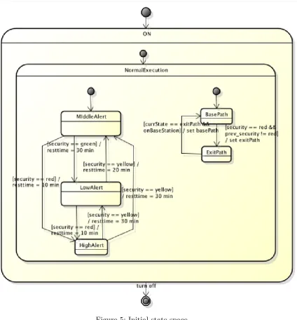
With the design choices known, the initial design can be implemented. This section describes how the base system design is implemented. The base system design is fixed and is used as a basis for both the OO and the AO implementation. Therefore the initial control part of the system is given in the form of a state space diagram; the reason for this is to abstract from language and method constraints.
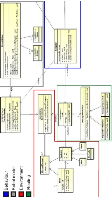
• Behaviour (blue) • Environment (red) • Routing (green)
The initial design is written in OO and provides all initial functionality to adapt system behaviour defined by the initial system requirements.
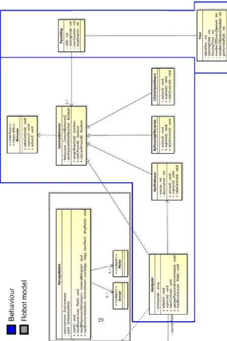
The behaviour is modelled as a subsumption architecture [34] which is illustrated in figure 4. The arbitrator takes various behaviours as input: CheckDoors, EvadeObstacle, FollowWall and Navigate. Each behaviour becomes active once it is triggered. Since the wall serves as a orientation point the robot moves forward along the wall; therefore this behaviour is active most of the time. If a door, crossing or obstacle is detected, other behaviours will take over control of the system. The navigator will update the position of the robot after a new waypoint is detected and passed. A path can be generated in different ways using the Strategy pattern [19]. Initially the system uses the Dijkstra shortest path [30, 31] strategy to navigate from one point in the environment to another. This system will function as the base system; it needs control to adapt to changes. Changes in the environment must be observed, analysed and adaptations must be applied depending on the state of the system.
Control loops The base system is controlled by several control loops. The control loop architecture will be described in MAPE-K [3] terminology: Monitor, Adapt Plan and Execute. The Knowledge Base will be hardcoded within the analyser components. The monitor component serves as the interface to observe the base-system. Concrete monitors must be defined to observe various parts of the system. The executor component serves to apply adaptations to the base system. These adaptations are triggered depending on the current state of the planner component. The initial requirements define various scenarios. Figure 5 gives an overview off all initial control states and their hierarchy. A state space diagram is chosen as representation method. The reason for this is to abstract from language and method constraints.
Figure 5: Initial state space
A tour is a patrolling cycle of the environment. The security state depends on the open doors found on the route. More open doors translate into a higher security threat. The overall security level of the system should be optimised. If there is a high security threat the patrolling rate should be intensified. A lower security threat means the system is safe so the interval between two tours can be extended. The interval between two patrolling tours will be adapted to the security state of the system.
4 Energy-aware Robot Design
Software evolution is scenario-driven; scenarios introduce new requirements which force the change or extension of a software program. So far in this case study, energy was not considered in the design; however, the best efforts were made to prepare the design for every possible evolution scenario. Energy is a relevant topic for possible evolution for a CPS; CPS often deals with energy management and in our robot case with a limited power supply. To extract energy evolution scenarios a domain analysis is conducted.
4.1 Domain Analysis
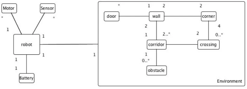
[image:36.595.98.508.382.530.2]Before energy scenarios can be considered the domain must be analysed. The domain can be divided into two parts namely the system, in this case the robot, and the world surrounding the system called the environment. The robot consists of various hardware parts like sensors, actuators (motors) and a power supply. Some level of abstraction is required here since not every part of the robot is relevant. For example the robot is built from various lego blocks; however it is not necessary to explicitly analyse every lego part used. The environment can be treated into endless detail; however for it to be useful to the robot again some abstractions must be applied. The robot model and the environment model are depicted in figure 6.
Figure 6: Domain model
4.2 Scenarios
The most simple scenarios are based on the robot itself; the robot consumes energy and it has sensors which can measure current and voltage. Measuring in itself is not a scenario; therefore an action or adaptation must be defined if the measured value is below or above a certain threshold.
Voltage in itself is no indication of the amount of energy left in a battery. However below a certain threshold it can be assumed the battery is almost empty. If this happens while the robot is away from its base-station (it is patrolling) there is a problem. If the robot runs out of energy during a patrolling cycle it will be stuck somewhere on the route without any options. At the base station a charger can be placed so the robot can recharge itself. In any case it is vital that the robot reaches the base station before it runs out of energy. The following two scenarios should make this possible:
V1: If the voltage reaches the critical point, abort the current task and return to the base station taking the shortest path.
V2: If the voltage reaches the critical point, only the behaviours responsible for moving must kept activated.
Both scenarios complement each other and can coexist; V2 increases the chance of success of scenario V1. Note that it is not certain that the robot will reach the base station. There is no historic energy consumption information, only a voltage threshold. If for some reasons the robot consumes more energy than assumed, the voltage may drop sooner than expected. Even if the robot notices in time the voltage drops below the threshold, this is not enough to ensure the robot reaches the base station.
Another scenario can be extracted by monitoring the current drawn from the power supply. If the drawn current is too high it could fatally damage the system. Although it must be noted this functionality is usually implemented by hardware we will still consider it. A current threshold could be defined just below the critical value to shutdown the system correctly instead of waiting for the hardware to shutdown the power supply. With this knowledge we can define another evolution scenario:
A1: If the current reaches the threshold value (a value just below the critical value), shutdown the system to prevent information loss.
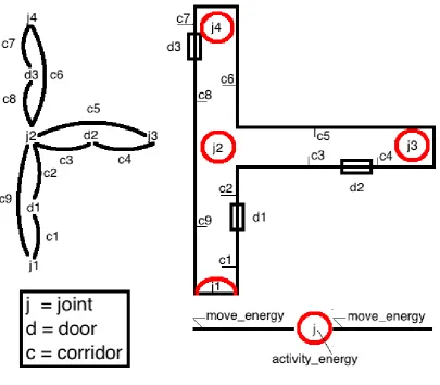
All of the scenarios so far are based on observing sensor values and taking action if a value becomes critical. Scenario V1 states that the robot should be able to reach the base-station at any time, however making this assumption based on voltage reading is far from reliable. Voltage by itself does not provide a reliable way to estimate how much energy is left in the power supply. For this reason energy data must be calculated and stored for future use.
the figure shows a graph model of the environment, whereas the right-hand side of the figure depicts the graphs nodes and edges within the actual environment.
Figure 7: Environment example
To estimate if the robot can return to the base station for every node and edge the energy consumption must be known. Energy consumption can be obtained by performing a exploration tour through the environment. During this tour energy consumption will be stored for each node and edge; this historic information should be used when planning a route through the environment. In this case, if the robot runs low on energy it can compare the energy left in the battery with the energy needed to travel the most energy efficient path back to the base station. If this check is performed at every new waypoint where the robot arrives, this will be far more reliable then only checking the voltage level.
• Power
P1: The system shall calculate the power for the entire system. (One current meter and voltage meter attached to the battery supply.)
• Energy
E1: Calculate energy consumption between two points in time. E2: The system can store energy measurements for later use.
E3: The system is able to travel between two waypoints using a path that con-sumes minimal energy. Energy management is based on historic information. E4: The system is able to return to the base station at all time before it runs out
of energy.
Where the first scenarios were almost entirely based on the system (the robot) there was no feedback from the environment model; the latter one introduces historic in-formation stored within the environment model which can be used to optimise energy management.
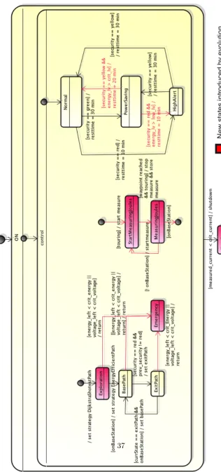
An entire new process is added to measure energy and can be seen in the middle of figure 8. This process measures energy and stores energy usage concerning waypoints and edges in the environment model. This new process is introduced by scenarios E1 and E2. Two new events are introduced: one to start measuring and one to stop measuring.
4.3 Evolution Impact on OO Implementation
In this section we will discuss the implementation for the initial base-scenario as well as the impact of the energy evolution scenarios on the initial design. The main focus is on the control part of the system and the interaction of the control system with the base system. The control-part of the system is implemented conform to the MAPE-K terminology. Challenges here are how to observe the base system’s properties of interest and how to apply adaptations to the base system without tangling the control loop architecture and the base system. Rewriting part of the base system to extend it with new functionality is deemed undesired. This section will assume the initial design of the base system and describe the control system architecture before and after evolution as well as the evolution impact on the base system.
4.3.1 Initial Control System Architecture
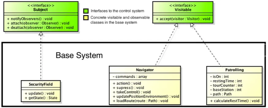
The observation interface of the control system architecture is implemented using the Observer pattern [19]. Observable subjects implement the subject interface of the Ob-server pattern, allowing them to be observed by multiple obOb-servers. The obOb-servers are automatically notified once the subject is updated by the base system. The observer must be registered to the subjects before they receive updates. In the control system architecture the monitor components are the observers; concrete monitors implement the observer interface.
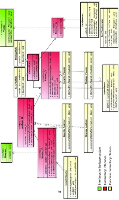
The complete control system implementation for the base scenario (without energy) is depicted in figure 9. The class diagram shows red classes which are the interfaces/ab-stractions of the four control loop components. Note that the controlState component is not a control loop class, the planner class contains states and depending on the state different adaptations can be applied. Green classes represent the Observer and Visitor pattern interfaces; they form the coupling between the control system and base system. All concrete control loop classes introduced by the base-scenario are coloured yellow.
4.3.2 Base-scenario Implementation
Two control loops can be distinguished in figure 9, namely the security-loop and system-mode-loop. Both loops share the mutual security-state monitor; the system-mode-loop adapts routing strategies according to this information, whereas the security-loop adjusts the resting time to the security state of the system.
[image:43.595.95.533.357.533.2]The observable and visitable components of the base system are depicted in figure 10. These are the components which supply information (observable) to the control loop and the components which allow the application of adaptations (visitable) to the base system.
Figure 10: Coupling control system architecture to the base system.
Initially only the security state is observed; depending on the state adaptations must be applied to the navigation and patrolling components. The current route of the robot can be adjusted in the navigator, whereas the resting time (time between two tours) can be adjusted through the patrolling class.
4.3.3 Energy-awareness Evolution Impact
the system’s evolvability energy-awareness functionality is introduced. By introducing energy-awareness functionality the number of observable and visitable components is increased. Figure 11 shows all new observable and visitable classes. Blue classes are newly introduced classes, red classes need modification to satisfy the new requirements.
Figure 11: Modification to the base system
Figure 11 shows the voltage and ampere fields (both data fields in the battery class modelled as a separate class) as two of the new observable classes (blue). These classes are introduced because before energy can be considered we need to measure voltage and current. With voltage and current known at a given moment in time, power (formula 2) can be calculated for that moment in time. Evolution scenario’s V1,V2, E3 and E4 adapt the behaviour of the robot. Because of this the navigator will need additional adaptations; new visitors must be declared to add additional adaptation functionality. Recall that the robot should be able to notice when it is running out of energy; the robot should return to the base station as soon as it is running low on energy. A new route must be calculated to navigate from the current position back to the base-station.
Figure 12: Ripples due to interface change visitor example
Figure 13: Scenarios for introducing new events.
Figure 14: Introduction of new states and events.
State space evolution of the planner leads to rewriting the state space context. The generic impact of state space evolution is shown in figure 14. New state fields and event handlers must be introduced to existing contexts. New event handlers affect the context interface. In our case the planner class is the context; therefore new event handlers must be added to the planner interface. This means that every concrete planner must make the new event handler concrete.