Interference Mitigation MAC Protocol for Cognitive Radio
Networks
*
Nasir Faruk1,Maaruf Ali2,Mohammed Ibrahim Gumel3
1
Department of Telecommunication Science, University of Ilorin, Ilorin, Nigeria; 2College of Computer Science & Engineering, University of Ha’il, Ha’il, KSA; 3Huawei Technologies, Kano, Nigeria.
Email: [email protected], [email protected], [email protected]
Received January 7th,2012; revised February 22nd, 2012; accepted February 29th, 2012
ABSTRACT
The growing demand for wireless services coupled with the limited availability of suitable electromagnetic spectrum is increasing the need for more efficient RF spectrum utilization. Spectrum allocated to TV operators can potentially be shared by wireless data services, either when the primary service is switched off or by exploiting spatial reuse opportu-nities. This paper describes a dynamic spectrum access scheme for use in the TV bands which uses cognitive radio techniques to determine the spectrum availability. The approach allows secondary users (SU) to operate in the presence of the primary users (PU) and the OPNET simulation and modelling software has been used to model the performance of the scheme. An analysis of the results shows that the proposed scheme protects the primary users from harmful in-terference from the secondary users. In comparison with the 802.11 MAC protocol, the scheme improves spectrum utilization by about 27% while limiting the interference imposed on the primary receiver.
Keywords: Dynamic Spectrum Access (DSA); Optimized Network Engineering Tool (OPNET); TV White Space; Cognitive Radio Networks; Signal-to-Interference Ratio (SIR)
1. Introduction
Wireless systems have become central to business and daily life. There are over five billion mobile cellular us-ers across the world, Parkes et al., [1] and the demand of the wireless technologies and services increases rapidly every year.
Globally, regulatory bodies are becoming aware of the significance of opening up the TV white space which would empower not only the spectrum utilization but also revenue generation. In the United States, the FCC approved the use of TV white space as unlicensed wire-less spectrum, Check et al., [2] in November, 2004.
In the United Kingdom OFCOM [3], OFCOM pub-lished proposals in July 2009 for opening up the TV white space to new applications. In Nigeria, the Nigerian Communications Commission, NCC [4], published a report on national radio frequency spectrum emphasizing on the development of comprehensive and clear-cut
poli-cies that will ensure that spectrum resource is optimally utilised for the overall benefit of the nation and therefore, to continue to adopt policies that will ensure that this scarce resource is well managed. Dynamic spectrum ac-cess (DSA) is a powerful new concept that promises to provide flexibility to spectrum management, thereby, overcoming the limitations of traditional command and control model which gives a licensed user an exclusive right to a fixed and static amount of spectrum without taking account the time varying nature in the demand of that occupied portion of the electromagnetic spectrum. The traditional spectrum allocation schemes are primar-ily focused on avoiding interference between the licensed (primary user) and unlicensed users (secondary users) without giving emphasis on the efficient utilization of the spectrum and the maximization of economic benefits in terms of revenue generation. Due to these, most of the spectrum is underutilized most of the time with low av-erage occupancy values of less than ten percent as re-ported by McHenry [5]. For economically driven dy-namic spectrum assignment to be optimally effective, a secondary market must exist that allows spectrum users to choose between capital investment and spectrum usage on a continuous basis, Caicedo and Weiss [6]. Erpek et al. [7], discuss the impact of man-made noise on the opera-*This paper is part A of ongoing research work. Part of this article is
tion of a wireless microphone using TV white space. In their work, they concluded that wireless microphones must have high carrier to noise ratio (CNR) values greater than 60 dB in order to operate reliably. Several MAC protocols have been proposed to implement dy-namic spectrum access. Optimization of spectrum sens-ing and the decision on spectrum access is proposed by Kim and Shin, [8]. Similarly in P. Papadimitratos et al., [9], negotiations among secondary users for spectrum access to avoid collision due to simultaneous transmis-sion have been reviewed. MAC protocols have also been proposed for multiuser wireless access, see Mullins [10].
Geirhofer et al. [11] propose a cognitive resource management protocol that, based on sensing, the infra-structure system allocates transmit power and transmis-sion time to reduce interference. This leads to an inter-ference-aware resource allocation. An electromagnetic interference (EMI) aware RTS/CTS protocol, P. Phun- chongharn et al., [12], for an infrastructure-based cogni-tive system was proposed. The system is designed to avoid harmful EMI caused to medical devices, which are considered to be primary users by allocating appropriate transmit power to the secondary user that satisfies the EMI constraint of the medical devices. The EMI immu-nity level is defined in terms of the electric field (meas-ured in Volt per meter) in which the medical devices can operate normally and the channel access mechanism was similar to IEEE 802.11 CSMA/CA MAC protocol. Auer et al., [13] propose an interference aware medium access for dynamic spectrum sharing; a receiver transmits a busy signal in an adjacent time multiplexed mini slot upon data reception. Through exploitation of channel reciprocity, other potential transmitters are prevented from interfering by first listening to the busy signal. This paper describes an electromagnetic interference avoid-ance (EMA) MAC protocol specifically designed to en-able dynamic spectrum access (DSA) to TV white space. The effect of the EMA on the performance of the cogni-tive system in terms of packet loss is investigated. The paper is organized as follows. In Section 2, a model to analyse the proposed system is described; Section 3 dis-cusses interference between the primary and the secon-dary user; Section 4 describes the proposed channel al-location scheme developed for the system; and perform-ance evaluation of the schemes is then given in Section 5. Finally, Section 6 concludes this paper.
Overview of Cognitive Radio Standards
Regulatory bodies have shown great efforts towards the achievement to enhance spectrum utilization. The FCC recently published the final rules in 2010 [14], that regu-late unlicensed secondary operation in TV white space where the devices are divided into two categories: fixed
and personal/portable [15]. Fixed devices can transmit up to 4 W equivalent isotropically radiated power (EIRP) with a power spectral density (PSD) of 16.7 mW/100 kHz. The fixed devices are restricted in operating on ad-jacent channels of active TV broadcasting channels. While the personal/portable devices are allowed to transmit with a maximum EIRP of 100 mW (with PSD of 1.67 mW/100 kHz) on channels non-adjacent to TV broadcast services and 40 mW (with PSD of 0.7 mW/100 kHz) on channels adjacent to an active TV broadcasting channel.
2. System Model
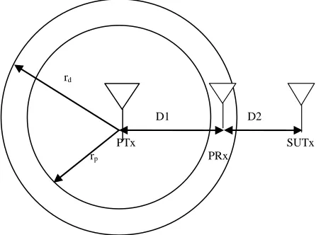
In the cognitive radio system proposed in this paper, the primary user is a TV operator using licensed spectrum, whilst, the secondary unlicensed users can only access the channel opportunistically. The transmission has to be controlled in such a way that the primary user (PU), is protected against electromagnetic interference and ex-cessive delay caused by the secondary user (SU). When a client node or user wishes to transmit on a channel it has to sense if the channel is idle before attempting transmis-sion, this is similar to IEEE 802.11. Therefore, a CSMA/CA MAC protocol is adopted and modified to provide cognitive capabilities. Consider a TV broadcast station (primary transmitter, PTx) on a high tower serv-ing a large radius of about 40km as shown in Figure 1. Spectrum holes could exist if the primary transmitter is not transmitting or the primary receivers, PRx, (TV re-ceivers) are not on. Without careful consideration of the activity of the primary user, the secondary transmitter could cause harmful interference to the primary receiver. Modelling of interference is needed to determine the conditions under which a secondary user can access the spectrum taking account of location and transmit power.
PTx
PRx
SUTx D1 D2 rd
[image:2.595.311.534.529.695.2]rp
The main task of the secondary system is to determine its position relative to the primary transmitters and receivers and to start transmission only if it is sure that it will not cause unacceptable interference to primary receivers.
Figure1 shows the primary receiver, PRx, located at a distance D1 from the primary transmitter, PTx and D2 is the distance between the secondary user transmitter, SUTx and the primary receiver, PRx. If the transmitter of the secondary user is far from the primary receiver, de-pending on the signal-to-interference ratio (SIR) limit at the receiver of the primary user, both the primary user and the secondary user could transmit data simultane-ously. The interference range is denoted by D2 in Figure 1. Assuming the radius rp represents the service area after the secondary user starts transmitting i.e. protection re-gion (rp) [16], where the primary receiver is guaranteed (i.e. the signal level from the PTx is high) to be able to detect the signal from the primary transmitter.
3. Interference and Channel Modelling
One of the most challenging problems of cognitive radio system is the interference which occurs when the SU accesses the spectrum but fails to become aware of the presence of a PU. Interference in the cognitive radio sys-tems will be a challenging issue, especially in areas of limited channel availability and where network coverage overlaps. Currently, heterogeneous networks share the unlicensed 2.4 GHz band, and interference among them has been the subject of extensive research. Interference cognitive radio networks are classified into two catego-ries [15].
3.1. Interference to/from Incumbents
If there is more than one primary system in the network, there could be interference between the systems as the results of adjacent channel operations. In some cases, the primary systems may interfere with the secondary sys-tems since the primary transmitter transmits with a high transmit power than the secondary systems. In some cases, this high-power interference may actually prevent the secondary devices to report incumbent detection. Avoidance of such interference depends on the location and channel gain between the primary user and secon-dary users [15]. Interference avoidance technique will provide a novel way of minimizing the interference be-tween the systems exploiting spatial reuse opportunities. The techniques are broadly classified into three groups: interference avoidance, interference control, and inter-ference mitigation.
In interference avoidance, Mitola III, 2000 [17], sec-ondary system access the spectrum using either time- division multiple access (TDMA) or frequency-division multiple access (FDMA) to avoid unacceptable
interfer-ence to primary receivers. Therefore, a cognitive tech-nique is required in this approach to detect and allocate the spectral holes. In the case of interference control sys-tem [18], the primary and secondary syssys-tems coexist on the same spectrum with interference within acceptable limits that would satisfy the quality of service require-ments of the primary system. In this view, the knowledge of such acceptable interference limits and its effects at the primary receivers is absolutely necessary. While, interference mitigation techniques are quite similar to interference control approaches but in this case adequate knowledge of primary system operation is necessary. Interference mitigation is further classified as opportun-istic interference cancellation (OIC) [19].
3.2. Interference amongst Secondary Users
Multiple secondary users may select the same TV chan-nel due to an uncoordinated selection process or limited availability. In such situations, ignorance of each other’s transmission may result in overlapping packets [15]. There are several factors that may affect the performance of the networks. Some include the transmit power control (TPC), which may result in better packet reception by the desired network but adversely affect other collocated networks. Other factors are the offered load and packet size. The overlap in time between transmissions of sec-ondary users will also result in interference, and the de-gree of this overlap and the overall traffic load define the level of interference. It is intuitive that shorter packets would incur lower interference (i.e., smaller packet loss probability) than larger ones, other parameters being equal. Additionally, if offered load in the system is very high, the degree of packets loss would be high which would then degrade the network throughputs.
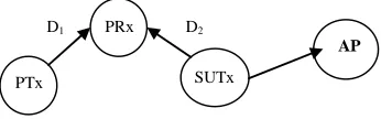
To address the aforementioned problems, a cognitive radio system needs a transmit power control scheme to allow the coexistence of the PU and SU without causing unacceptable interference between them. Figure2 shows the interfering signal at the primary receiver. The sig-nal-to-interference ratio depends on the secondary user transmitter power and the distance from the primary re-ceiver. AP is the access point (cognitive radio network base station). The signal strength at both the PRx (pri-mary user receiver) and the SURx (secondary user re-ceiver since the secondary user is a transre-ceiver) is deter-mined by the path loss. There are many published path loss models for a cognitive radio [20].
D1 PRx D2
PTx SUTx
[image:3.595.339.512.668.722.2]AP
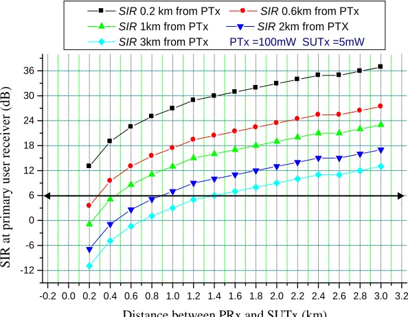
receiver as a function of the distance between the pri-mary user receiver and the secondary user transmitter. When the transmit power of the primary transmitter is 100 mW and the secondary user is transmitting at 5 mW. At 0.2 km from the primary transmitter and 0.2 km from the secondary transmitter, the SIR is 13 dB and this in-creases when the primary receiver moves away from the secondary transmitter and this can be up to 36.9 dB when they are 3 km apart. When the primary receiver moves 1 km from the primary transmitter and 200 m from the secondary transmitter, the SIR degrades to about 0dB. This shows that location of primary transmitter, transmit power of primary transmitter, secondary transmitter loca-tion and transmit power of secondary transmitter are key parameters to be considered/controlled when modelling of interference. The main challenge is to determine the optimal transmit power and distance of the secondary user transmitter that will not degrade the SIR at the pri-mary receiver below the threshold level. In order to cor-rectly interpret the received signal at the primary receiver, the SIR must be above a given threshold. Different cel-lular systems require different SIR thresholds 18 dB, 14 dB, and 9 dB are required as the minimum acceptable SIR protection levels in Advanced Mobile Phone System (AMPS), Digital Time Division Multiple Access (TDMA) Such as IS-136, and Global System for Mobile Commu-nication (GSM), respectively [21]. In this case 6 dB was chosen as the minimum SIR at the primary receiver. In Figure3, when the primary receiver is 2 km from the primary transmitter (PUTx), the minimum distance the secondary transmitter has to be from primary receiver is 800 m in other to meet the target of 6 dB SIR. Thus, this In this paper, the free space path loss (FSPL) model
has been used as this gives the worst case interference. The FSPL at a given distance between any two users or access point is given by Equation (1) below:
dB 20 log
20 log
32.45FSPL d f (1)
where d is the distance in km and f is the frequency in MHz. The SIR (signal-to-interference) is defined as the ratio of the wanted signal from the primary user trans-mitter (PTx) and the unwanted signal from the secondary user transmitter (SUTx) when considering a single pri-mary receiver and secondary transmitter in Figure2.
R i
SIRP P (2)
where Pi is the interference power in dBm from the SUTx, PR is the received power in dBm and SIR is the signal-to-interference ratio in dB at the primary user re-ceiver. The simulation was carried out using wireless nodes with an operating transmission frequency of 2.4 GHz, receiver sensitivity of –95 dBm and speed of propagation 3 × 10⁸ m/s at a distance of 0 - 3 km between the SUTx and the PRx. The result is shown in the Fig-ures3 and 4. The primary receiver communicates with the primary transmitter whose signal varies with distance from its location. At the same time it receives unwanted signals from the secondary transmitter which is located at some certain distance as shown in Figure 1. The re-ceived signal quality at the primary receiver is typically measured by the signal-to-interference ratio (SIR) which is the ratio of the power of the wanted signal and the ag-gregated power of the unwanted signals. Figure3 below shows the signal to interference ratio (SIR) at the primary
-0.2 0.0 0.2 0.4 0.6 0.8 1.0 1.2 1.4 1.6 1.8 2.0 2.2 2.4 2.6 2.8 3.0 3.2 -12
-6 0 6 12 18 24 30 36
SIR 0.2 km from PTx SIR 0.6km from PTx
SIR 1km from PTx SIR 2km from PTX
SIR 3km from PTx PTx =100mW SUTx =5mW
SIR
a
t p
rimary
user r
ece
iv
er
(dB
)
[image:4.595.149.446.482.713.2]Distance between PRx and SUTx (km)
indicate that, the secondary transmitter is free to transmit on the channel once it is 800 m radius from the primary receiver i.e. (the talk zones) while any transmission within a distance less than 800 m radius is not permissi-ble. In other words, 800 m radius is the non-talk region. This region increases to 1.4 km as the primary receiver moves 3 km from the primary transmitter (PUTx).
3.3. Maximum Allowable Transmission Distance between the Secondary User Transmitter and the Primary User Receiver at a Target 6 dB SIR
Based on the analysis of service area, talk zones, non-talk zones and target SIR, the maximum permissible trans-mission distance for SU from the PU receiver at any given distance of the primary receiver from the primary transmitter as a function of transmit power of the secon-dary transmitter is evaluated i.e. the values of Ds for dis-tance of 3 km radius in Figure 1 have been determined as shown in Figure4.
In Figure 4, when the PRx is 1 km from the PTx transmitting at 100 mW, and SUTx power is 5 mW, at a target SIR of 6 dB, the non-talk region for SUTx is from 0 - 0.6 km. This distance increases to 1km when the PU receiver moves 2 km away from the primary transmitter, and 1.2 km when the SU transmit power is increased to 10 mW. A transmit power control scheme have been designed and the relative positions of the secondary user with respect to the primary receiver have been deter-mined, this will enable the coexistence of the secondary user without causing interference to the primary user in the cognitive radio network.
4. Channel Allocation and Access
Under this infrastructure-based cognitive radio system model, every secondary user transmits its data through the access point. The access point uses the information about the primary receiver to determine whether to allow the secondary transmission or not. Both the access point (AP) and secondary users perform periodic channel sensing. The sensing results from the SU users are sent back to the AP to construct a spectrum occupancy/ availability map for each geographical location. To ini-tiate connection with the AP, the SU performs spectrum sensing based on primary transmitter energy detection [9] and identifies the available white space (i.e. whether the primary transmitter is ON or OFF). Based on this white space, the SU then scans for a synchronization channel (SCH) transmitted from the AP, this is a beacon which is broadcast from the AP to all secondary users within the cell for time synchronisation and resource allocation information. After the SCH is received, the SU initiates a connection by sending the request-to-send (RTS) packet.
Based on the sensing results (i.e. whether the primary transmitter is ON/OFF), if the PTx is ON, the AP per-forms admission control tests. In the presence of a PRx, the AP determines if the SUTx is within the interference range of the PRx, this is done by computing the distance of the SUTx to the PRx using the signal transmitted by the SUTx. If it is not, the AP computes the appropriate transmission parameters (i.e. the maximum allowed transmit power for the secondary user to avoid unac-ceptable interference at the PRx) and this information is sent back with a “clear to send” (CTS) signal to the
sec-0.0 0.2 0.4 0.6 0.8 1.0 1.2 1.4 1.6 1.8 2.0 2.2 2.4 2.6 2.8 3.0 3.2 0.0
0.2 0.4 0.6 0.8 1.0 1.2 1.4 1.6 1.8 2.0 2.2 2.4 2.6 2.8 3.0 3.2
SUTx 5mW SUTx 10mW SUTx 20mW SUTx 40mW SUTx 60mW PTx 100mW
D
is
ta
n
ce
b
etw
ee
n
P
U
r
ece
iv
er
an
d
S
U
tra
n
sm
it
te
r (k
m
)
[image:5.595.134.465.490.715.2]Distance between PU Receiver and Primary Transmitter (km)
ondary user. If the secondary user is within the interfer-ence range of the primary receiver, the request for data transmission from the user would be rejected and no CTS signal returned. The AP knows about the presence of primary receivers and their locations since the interfer-ence occurs at the primary receiver and the secondary user has to pass through admission control tests as de-scribed above. The primary receiver usually emits some local oscillator (LO) leakage power from its antenna ter-minal when it receives signals from the primary trans-mitter [22]. In order to reliably determine the location of the primary receiver, a primary receiver detection method would be used to exploits the LO leakage power instead of relying only on the signal from the primary transmitter and detects the presence of the primary re-ceiver directly. The leakage primary rere-ceiver power may be up to –90 dBm [23]. To improve sensing performance, memory sensors could be attached to the primary receiv-ers, the sensor will send a beacon signal, which can be detected by the AP, indicating when the receiver is active and using this beacon signal, the AP could compute the sensor’s location and using this information gathered by the cognitive network will guarantee that the secondary users will not cause severe interference that would de-grade the signal-to-interference ratio at the primary re-ceivers.
5. Simulation and Results
The performance of the cognitive CSMA/CA protocol is analysed by studying the interference the secondary user transmitter causes to the primary user receiver, and how this interference affects the performance of the network in terms of retransmission as a results of packet loss and its impact on the network throughput. OPNET version 14.5 is used to simulate the network performance. The network model assumes a network area of 4 km × 4 km with four wireless local area network (WLAN) nodes, the primary transmitter, primary receiver, access point and the secondary user as shown in Figure 2 above. All simulations are run for 300 s. A centralised access scheme has been considered, where the SU communicates with the AP that collects all the information from a collabora-tive group of secondary users and learns about the pri-mary user activity. The data rate for each user is 11 Mbps and the packet inter arrival rate follows the exponential distribution with a mean value of 1000 packets/sec. The packet size is also an exponential distribution with a mean value of 1024 bytes. Since the packet size is below the 2034 bytes limit, fragmentation is not needed. Direct sequence spread spectrum (DSSS) is used for both users; the channel access mechanism is based on the CSMA/ CA MAC protocol and the IEEE 802.11b.
5.1. Traffic Generation and Channel Usage Pattern
A traffic flow control mechanism based on an events based technique is deployed to model the primary user activity to generate an ON/OFF traffic over the period of 300 s, the ON periods are the busy time and the OFF periods are the idle times for secondary access [16].
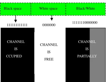
Figure 5 illustrates the 0/1 states, 0 denoting the channel is free and 1 denoting the channel is busy and occupied by the primary user, these 0/1 alternating stages is referred to as the channel usage pattern and the OFF periods represents the spectrum opportunists or spectrum hole commonly known as white space. The secondary user has the ability to detect the OFF times of the pri-mary user and transmit packets over the white space if it is not within the non-talk zone of the primary receiver. The black spaces are not good candidates for dynamic spectrum access as the secondary user will cause severe interference to the primary user which would degrade the minimum SIR at the primary receiver. However, the white spaces can be use for dynamic spectrum access. In this research, we assume all the OFF periods from a pri-mary user transmission are considered as white spaces and can be identified instantaneously.
5.2. Performance In Terms of Electromagnetic Interference (EMI) Avoidance and Packet Loss
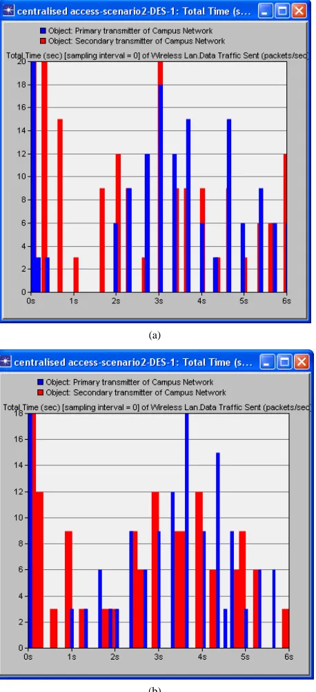
A time slot RTS/CTS channel access mechanism was used by both PU and SU. Figure 6(a) above shows the interference at primary user receiver (PRx), as a result of secondary user (SU), transmission using the traditional CSMA/CA protocol within the period of first six seconds. The blue bars represent primary user transmission and the red bars denoted the secondary user transmission. The overlaps between the red and blue bars are estimated to be up to 90% around 3 s and 4 s. Figure 6(b) shows
111111111111 0000000 11111110000000 Black space White space Black/White
CHANNEL
IS
CCUPIED
CHANNEL
IS
FREE
CHANNEL
IS
[image:6.595.313.533.549.719.2]PARTIALLY
(a)
[image:7.595.60.289.86.588.2](b)
Figure 6. Screenshot showing the interference at primary user receiver (PRx) due to secondary user transmission using (a) traditional CSMA/CA and (b) cognitive CSMA/ CA MAC protocol within a period of 6 s.
overlap of primary and secondary user transmission when using cognitive CSMA/CA MAC protocol. The thickness of the red bars indicates SU transmissions of packets twice or three times within the white space (since the secondary user’s transmission is continuous within the periods of white space to increase channel utilization). The transmission overlaps indicate interference at
pri-mary receiver due to secondary user transmission. The interference of the proposed dynamic spectrum access model is less than that of traditional CSMA/CA protocol as it allows white space to be detected so transmission occurs at an appropriate time, rather than sending a RTS and not getting CTS. This makes better use of the avail-able white space. This provides optimal channel access control policy for the secondary users in cognitive radio networks. Optimization of the maximum permissible transmission distance for secondary user transmission would provide a better performance in the network. Simulation using OPNET indicates a maximum packet loss of 1.5% is experienced at the primary receiver using the traditional CSMA/CA protocol while the simulation indicates a maximum of 0.001% loss when employing the cognitive CSMA/CA protocol. These values were obtained by comparing the packets sent by the primary transmitter and the received packets at the primary re-ceiver. This indicates that the overall network throughput per unit time of the cognitive protocol is better than that of CSMA/CA protocol. For packet loss intolerant appli-cations such as VOIP even a packet loss of 1% can sig-nificantly degrade a VOIP call [24]. Further analysis has been carried out on the effects of the relative positions of the SUTx to the PRx on packet loss. Results indicate that there is a higher packet loss when the secondary user is transmitting within the non-talk zones[16] i.e. distance less than 200 m from the primary receiver, any transmis-sion within the non-talk zonewould degrade the SIR at the primary receiver by 6 dB. The further away the sec-ondary transmitter was from the primary receiver, the less interference it caused and low packet loss was re-corded. In conclusion, for optimum channel access con-trol policy, the interference range D2 for the primary receiver must be maintained.
5.3. Performance in Terms Spectrum Utilization Efficiency as a Function of the Number of Secondary Users
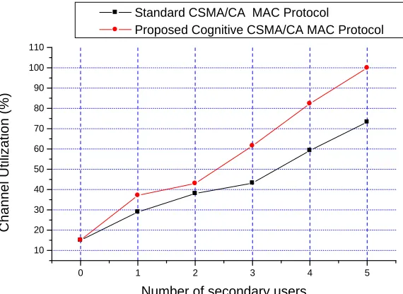
Network throughput is the average rate of successful packet delivery over the channel. Throughput can be normalized and measured relative to the channel bit rate in bits/s to obtain the channel utilization. Figure7 shows the channel (spectrum) utilization as a function of the number of secondary users for both the standard CSMA/ CA MAC protocol and the proposed cognitive MAC protocol. The data rate for each user is 11Mbps and the packet inter arrival rate follows the exponential distribu-tion with a mean value of 1000 packets/sec. Spectrum utilization of about 15% is measured when only the pri-mary user is transmitting. When secondary users start transmitting on the channel, the proposed MAC protocol
ives a better throughput than the standard CSMA/CA g
0 1 2 3 4 5 10
20 30 40 50 60 70 80 90 100 110
Standard CSMA/CA MAC Protocol
Proposed Cognitive CSMA/CA MAC Protocol
Chann
el
Ut
ili
z
a
ti
on (%
)
[image:8.595.155.440.86.294.2]Number of secondary users
Figure 7. Spectrum utilization.
protocol, as it limits the transmit power and range for the secondary transmitter to avoid interference to the primary receiver. From Figure 7, the spectrum utilization is 99.91% and 73.31% when five secondary users are ac-cessing the network for the proposed MAC protocol and standard CSMA/CA protocol respectively. It shows that the proposed protocol improves spectrum utilization by about 27% while limiting the interference imposed on the primary receiver.
6. Conclusion
Regulatory bodies are becoming aware of the signifi-cance of opening up the TV white space which would give an improvement in the spectrum utilization and also lead to increased revenue generation. The design of an efficient MAC protocol for DSA is the key to the success of cognitive radio networks. A MAC protocol for DSA has been proposed for use in a wireless regional area networks (WRAN). The performance of this protocol has been analysed by simulation and the results show that the proposed scheme improves the spectrum utilization effi-ciency by about 27%. It also protects the primary user from interference from secondary users and reduces the packet loss to about 0.001% which is about three orders of magnitude lower than the standard CSMA/CA MAC protocol.
REFERENCES
[1] S. Parkes and S. Teltscher, “ITU Sees 5 Billion Mobile Subscribers Globally in 2010,” International Telecommu- nications Union Press, Geneva, 2010.
http://www.itu.int/newsroom/press_releases/2010/06.html [2] W. A. Check, A. Scott, S. L. Mace, D. L. Brenner and D.
Nicol, “Unlicensed Operation in TV Broadcast Bands,” Report and Order Memorandum Opinion FCC 10-174, 2004.
http://www.google.co.uk/url?sa=t&rct=j&q=unilicensed %20operation%20in%20the%20tv%20broadcast%20band s&source=web&cd=1&ved=0CCcQFjAA&url=http%3A %2F%2Fwww.ncta.com%2FDocumentBinary.aspx%3Fi d%3D151&ei=4d8WT9urM-r44QSx98iTBA&usg=AFQj CNHyo2NO15jeifSLvITxboJ_7EAKVA&sig2=j6NFMV F-UpXK9DmoujBOIQ&cad=rja
[3] OFCOM, “Digital Dividend: Cognitive Access, Statement Licence-Exempting Cognitive Devices Using Interleaved Spectrum,” 2009.
http://stakeholders.ofcom.org.uk/binaries/consultations/co gnitive/statement/statement.pdf
[4] NCC, “Commercial Frequency Management Policy, Ad- ministrative Procedures and Technical Guidelines,” 2007. http://www.ncc.gov.ng/component/docman/doc_downloa d/137-commercial-frequency-management-policy-admini strative-procedures-a-technical-guidelines.html
[5] M. A. McHenry, P. A. Tenhula, P. A. McCloskey, D. A. Roberson and C. S. Hood, “Chicago Spectrum Occu-pancy Measurements and Analysis and a Long Term Studies Proposal,” Shared Spectrum Company, Vienna, 2005.
http://www.wtapas.org/final-papers/ChicagoSpectrum-Mc Henry-Session-I-1.pdf
[6] C. E. Caicedo and M. B. H. Weiss, “The Viability of Spec- trum Trading Market,” IEEE Communication Magazine, Vol. 49, No. 3, 2011, pp. 46-52.
doi:10.1109/MCOM.2011.5723799
[7] T. Erpek, M. A. Mchenry and A. Stirling, “Dynamic Spec- trum Access Operational Parameters with Wireless Mi- crophones,” IEEE Communication Magazine, Vol. 49, No. 3, 2011, pp. 38-45. doi:10.1109/MCOM.2011.5723798 [8] H. Kim and K. G. Shin, “Efficient Discovery of Spectrum
dio Networks,” IEEE Transactions on Mobile Computing, Vol. 7, No. 5, 2008, pp. 533-545.
doi:10.1109/TMC.2007.70751
[9] P. Papadimitratos, S. Sankaranarayanan and A. Mishra, “A Bandwidth Sharing Approach to Improve Licensed Spectrum Utilization,” IEEE Communications Magazine, Vol. 43, No. 12, 2005, pp. S10-S14.
doi:10.1109/MCOM.2005.1561918
[10] B. E. Mullins, “CATER: An Opportunistic Medium Ac-cess Control Protocol for Wireless Local Area Networks,” PhD Thesis, Virginia Polytechnic Institute and State Uni- versity, Blacksburg, 1997.
http://scholar.lib.vt.edu/theses/available/etd-52497-15105 5/unrestricted/mullins.pdf
[11] S. Geirhofer, T. Lang and B. M. Sadler, “Interference- Aware OFDMA Resource Allocation: A Predictive Ap- proach,” IEEE MILCOM Military Communications Con- ference, San Diego,16-19 November 2008, pp. 1-7. [12] P. Phunchongharn, E. Hossain, D. Niyato and S. Camor-
linga, “A Cognitive Radio System for E-Health Applica- tions in a Hospital Environment,” IEEE Wireless Com- munications, Vol. 17, No. 1, 2010, pp. 20-28.
[13] G. Auer, H. Haas and P. Omiyi, “Interference Aware Medium Access for Dynamic Spectrum Sharing,” 2nd IEEE International Symposiumon New Frontiers in Dy- namic Spectrum Access Networks, Dublin, 17-20 April 2007, pp. 399-402.
[14] FCC, “FCC Officially Frees TV White Space Spectrum,” 2010.
http://news.cnet.com/8301-30686_3-20017435-266.html [15] C. Ghosh, S. Roy and D. Cavalcanti, “Coexistence Chal-
lenges for Heterogeneous Cognitive Wireless Networks in TV White Spaces,” IEEE Wireless Communications, Vol. 18, No. 4, 2011, pp. 22-31.
[16] R. Tandra, A. Sahai and V. Veeravilla, “Unified Space- Time Metrics to Evaluate Spectrum Sensing,” IEEE Wire- less Communication Magazine, Vol. 49, No. 3, 2011, pp. 54-61.
[17] J. Mitola III, “Cognitive Radio: An Integrated Agent Ar- chitecture for Software Defined Radio,” PhD Thesis, Royal Institute of Technology,Sweden, 2000.
http://www.google.co.uk/url?sa=t&rct=j&q=cognitive%2 0radio%3A%20an%20integrated%20agent%20architectur e%20for%20software%20defined%20radio&source=web &cd=1&ved=0CCkQFjAA&url=http%3A%2F%2Fwww. diva-portal.org%2Fsmash%2Fget%2Fdiva2%3A8730%2 FFULTEXT01&ei=lsQWT87UFOen4gTitL2oBA&usg= AFQjCFoQWgdlSj7288L5xj_bbrVpBNCtw&sig2=baDm pwki0Mb1HJXcTAGLrA&cad=rja
[18] A. Ghasemi and E. Sousa, “Capacity of Fading Channels under Spectrum-Sharing Constraints,” Proceedings of IEEE International Conference on Communications, Istanbul, 11-15 June 2006, pp. 4373-4378.
[19] E. Hossain, L. Le, N. Devroye and M. Vu, “Cognitive Radio: From Theory to Practical Network Engineering,” In: V. Tarokh, I. F. Blake and A. Gulliver, Eds., Advances in Wireless Communications, Springer, Berlin, 2009, pp. 1-41. http://www.ece.uic.edu/~devroye/research/ch4.pdf [20] A. F. Molisch, L. J. Greenstein and M. Shafi, “Propaga-
tion Issues for Cognitive Radio,” Proceedings of the IEEE, Vol. 97, No. 5, 2009, pp. 787-804.
doi:10.1109/JPROC.2009.2015704
[21] Lecture Note, 2010.
http://www.cs.nctu.edu.tw/~yi/Courses/WirelessOPT/Lec tureNotes/lecture01.pdf
[22] B. Wild and K. Ramchandran, “Detecting Primary Re- ceivers for Cognitive Radio Applications,” 1st IEEE In- ternational Symposium on New Frontiers in Dynamic Spectrum Access Networks, Baltimore, 8-11 November 2005, pp. 124-130.
http://www.eecs.berkeley.edu/~dtse/3r_ben_dyspan05.pdf [23] S. M. Weiss, R. D. Weller and S. D. Driscol, “New Meas- urements and Predictions of UHF Television Receiver Local Oscillator Radiation Interference,” Merrill Weiss Group, Metuchen, 2006.
http://h-e.com/sites/h-e.com/files/tech_docs/rw_bts03.pdf [24] C. Lewis and S. Pickavance, “QoS Requirements for
Voice, Video, and Data,” In: C. Lewis and S. Pickavance, Eds., Selecting MPLS VPN Services, Cisco Press, Indian- apolis, 2006.