ISSN Online: 2333-9721 ISSN Print: 2333-9705
DOI: 10.4236/oalib.1104495 Mar. 30, 2018 1 Open Access Library Journal
Hydraulic Ripper Computer Modeling and
Simulation
Yanping Huang, Guoping Yang
Shanghai University of Engineering Science, Shanghai, China
Abstract
It’s very useful to put the virtual prototype technology into hydraulic ripper, just for improving the product research and development efforts. A certain type of hydraulic ripper was simulated and calculated using CATIA and ADAMS software, the simulation system is set up, and the relevant parame-ters of hydraulic ripper are gotten; on this basis, a prototype model is com-pared with the reality. At the same time, a comparative analysis of simulation results and real results under certain conditions is used to verify the rationali-ty of the protorationali-type model, and the reference value of its products must build a good development platform for hydraulic ripper.
Subject Areas
Mechanical Engineering
Keywords
Hydraulic Ripper, ADAMS, CATIA, Modeling Simulation
1. Introduction
Hydraulic ripper is a kind of broken hammer in recent years, domestic research in this area less, but some domestic enterprises and universities in this area car-ried out a systematic study. However, with the research of virtual prototyping, it is more and more important to analyze the structure and system of Hydraulic ripper. In this paper, the research of Hydraulic ripper is carried out by using CATIA for 3D modeling, and then introduced into the simulation software ADAMS. Then, the parameters are added and simulated by using the View module in ADAMS of multi-body system dynamics software. Through this se-ries, the simulation results are compared with the real results to verify the ratio-nality and validity of the data and simulation, and the feasibility of applying the
How to cite this paper: Huang, Y.P. and Yang, G.P. (2018) Hydraulic Ripper Computer Modeling and Simulation. Open Access Library Journal, 5: e4495.
https://doi.org/10.4236/oalib.1104495
Received: March 11, 2018 Accepted: March 27, 2018 Published: March 30, 2018
Copyright © 2018 by authors and Open Access Library Inc.
This work is licensed under the Creative Commons Attribution International License (CC BY 4.0).
DOI: 10.4236/oalib.1104495 2 Open Access Library Journal
mechanism The cushioning mechanism is mounted on the upper surface of the crushing mechanism mounting table [1]. Its working principle is through the excavator to provide high-speed hydraulic oil, pipeline from the Hydraulic rip-per connected to the hydraulic motor, hydraulic motor through the spline and the shaft connected with the eccentric block gear through the key and the shaft, hydraulic The motor rotates the drive shaft and the shaft drives the drive wheel of the eccentric block gear. The active eccentric wheel drives the driven eccentric wheel to rotate, and the pair of meshing with the eccentric gear rotates, resulting in eccentric forces superimposed in the vertical direction, The direction of each other to offset each other, through the upper and lower vibration gear and knife row connected to the broken force to the bucket teeth, in this role under the cracked stones to achieve the crushing effect [2].
3. Hydraulic Ripper Model Established
3.1. Establishment of 3D Model in CATIA
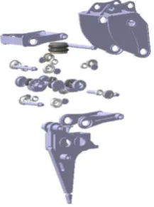
According to a Hydraulic ripper, in the CATIA environment to establish three parts of the three parts of the model and assembly, as shown in Figure 1 is a Hydraulic ripper explosion map, through the explosion map can be a good show about the relationship between the various parts of Hydraulic ripper, this simple design language to a large extent facilitate the exchange of technical personnel, reducing the various aspects of the error [3][4].
3.2. Establishment of Virtual Prototype Model in ADAMS
Before modeling with the software ADAMS software module, the construction of the mechanical system model must be carried out. Some of the common con-straints and forces, geometric models and a series of settings, and then parame-tric analysis.
1) Hydraulic ripper into ADAMS software
DOI: 10.4236/oalib.1104495 3 Open Access Library Journal Figure 1. Hydraulic ripper explosion map.
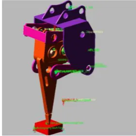
modules into the Adams, respectively, for example, into the ADAMS shell, re-spectively, attached to the quality, moment of inertia, moment of inertia, cen-troid coordinates (Figure 2).
2) Motion constraint add
After importing into ADAMS through CATIA software, in order to ensure that the simulation is performed correctly, constraints must be added to con-strain the motion direction and motion of the moving parts.
1) Contact constraints
There are two constraints in this model: two gears with eccentric blocks, bucket teeth and broken objects. The impact function model is expressed by dis-placement, velocity, and contact force. The characteristics of this method are ap-plicable to all cases of continuous and discontinuous type of contact force [5]. According to the characteristics of Hydraulic ripper, the impact function model is selected to define the contact constraint of this model.
2) Rotate the sub-constraint
The rotary pair is often used for two objects so that the member 1 rotates rela-tive to the member 2 for rotation. The simplified Hydraulic ripper has six rotary pairs, in which the housing is connected with the pull-up bracket, the housing and the pull-up the bracket and the shock box, the pull-down bracket and the shock box, the vibration box and the active component, the vibration box and the driven component, all six are the rotation vice.
3) Other constraints
The model of the Hydraulic ripper is simulated in the course of the stone fixed on the earth, the chassis selection fixed pair of fixed and the earth fixed, shock box, knife row, bucket teeth selection associate association, in this process for the air spring The treatment is handled according to a contact spring.
3) Drive the addition
DOI: 10.4236/oalib.1104495 4 Open Access Library Journal Figure 2. The virtual prototype model of
Hydraulic ripper in ADAMS.
hydraulic breaker hammer speed of 1500 r/min to 1800 r/min when the best blow to break the effect, we choose this Range of the study, 1800 r/min step function for the STEP (time, 0, 0, 0.05, 10800 d).
4) Establish measurement and simulation control settings
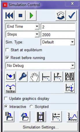
The purpose of the virtual prototype model is to obtain a series of data on the acceleration and velocity, displacement and energy of the bucket teeth of the Hydraulic ripper. We set the simulation time 2 s, simulation steps 2000, set the Figure 3.
4. Simulation Results Analysis
After the simulation is completed, we can call ADAMS/Post Processor post-processing module to view and analyze the simulation data obtained in this simulation, through simulation, we got the hydraulic ripper bucket teeth speed, acceleration, displacement and energy of the dynamic curve, the detailed results are shown in Figures 4-8.
As can be seen from Figure 4, the stroke in the direction of gravity is 35.1 mm, the process of running is stable, has been stable within a certain range, the displacement of the extreme position of the slight fluctuations, this is because the high frequency Hydraulic crusher in the process of breaking the stones, the stones will be broken, so there will be displacement deviation.
As can be seen from Figure 5, the displacement stroke in the direction of the tool nose is 0.498 mm, less than 1 mm, and it is in a steady state at the limit posi-tion. There is no fluctuation in the displacement.
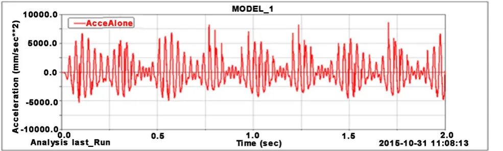
As can be seen from Figure 6, the period of motion is T = 0.0375 s, and the number of blows per minute is 1600 times, which is in line with the number of strikes per minute 1500 - 1740 provided by the manufacturer. In the course of the movement, firstly the bucket accelerates at an acceleration of 69.57 m/s2.
Af-ter the collision, the maximum acceleration reaches 394.05 m/s2. It can be seen
that when the acceleration is greater than After 247.56 m/s2, the combination of
[image:4.595.302.443.72.212.2]DOI: 10.4236/oalib.1104495 5 Open Access Library Journal Figure 3. Simulation control settings.
Figure 4. Bucket teeth displacement curve in the direction of gravity.
Figure 5. Bucket teeth displacement curve in the direction of knife board.
It can be seen from Figure 7 that when the operation is started, the accelera-tion in the direcaccelera-tion of the knife is relatively small, the acceleraaccelera-tion is 1.285 m/s2,
[image:5.595.60.539.508.651.2]DOI: 10.4236/oalib.1104495 6 Open Access Library Journal Figure 6. Bucket teeth acceleration curve in the direction of gravity.
Figure 7. Bucket teeth acceleration curve in the direction of knife board.
Crushing little effect, so we can ignore the impact of its acceleration on the per-formance of Hydraulic ripper.
It can be seen from Figure 8, the maximum impact energy of Hydraulic ripper can reach 1817.7 J, at the moment of start, Hydraulic ripper energy reached 843.6 J, in the subsequent work process, the basic distribution of energy, To a certain extent, a true reflection of the Hydraulic ripper the real working state, the parameters have a certain reference value.
As can be seen from Table 1, the virtual prototype model of the simulation results and the real results there are still many gaps, these may be the virtual prototype in the simulation process abandoned part of the useless parts and simplified, and has not yet taken into account The impact of lubricants on the organization, if these factors can be taken into account, the simulation results and the difference between the official data should not be now big.
5. Conclusion
[image:6.595.58.551.242.390.2]DOI: 10.4236/oalib.1104495 7 Open Access Library Journal Figure 8. Hydraulic ripper impact energy curve.
Table 1. Data comparison table.
Content Bucket teeth trip (mm) Impact speed (m/s) Hit frequency (Hz) Maximum impact energy (J)
Official data ≤50 ≤2.3 25 - 29 2500
Simulation data 35.1 1.1 26.6 1817.7
process, and to provide the basis for this basis [6]. The application of virtual prototyping technology in hydraulic ripper is not only theoretical, but also has great practical value. Hydraulic ripper was simulated and analyzed in ADAMS software to obtain a series of parameters and the movement characteristics curve of the bucket tooth. Based on the reference, the displacement, acceleration, and frequency movement rules of the bucket teeth were analyzed. Based on the pa-rameters curve of the production punching skill, the simulation results obtained are close to the parameters provided by the manufacturer, which verifies the correctness of hydraulic ripper model under certain assumptions.
References
[1] Cao, Y. and Fan, Y.X. (2012) A High-Frequency Hammer: China, 202590877U. 2012-12-12.
[2] Wang, K.L., Yang, G.P., Hu, K.J., et al. (2015) High Frequency Hammer Develop-ment Status and Research. Mining Machinery, No. 4, 1-4.
[3] Wang, L. and Yang, G.P. (2011) Computer Modeling and Simulation of Hydraulic Breaking Hammer. Machine Tool & Hydraulics, 39, 88-92.
[4] Yang, G.P., Liu, X.J., Gao, J.H., et al. (2011) Improved Design of Hydraulic Impac-tor Based on Virtual Prototyping Technology. Mechanical Design and Manufacture, No. 8, 22-24.
[5] Pei, W.C., Li, Y.G., Li, Y.H., et al. (2008) Impact Model Based on Virtual Prototyp-ing Technology—The Impact Model of ADAMS. Journal of HeBei Polytechnic University (Natural Science Edition), 30, 59-63.
[image:7.595.62.538.278.330.2]