An Ameliorated Approach to Represent UML Class
Diagram in the Table Format
R. N. Kulkarni, PhD
Prof. & Head,
Dept. of Computer Science & Engineering,
BITM, Ballari, India
C. K. Srinivasa
Associate Prof.,
Dept. of Computer Science & Engineering,
BITM, Ballari, India
ABSTRACT
Nowadays Unified Modeling Language (UML) is a de-facto standard tool used for the design of software systems. The UML tool has the facility to perform forward engineering and reverse engineering of the UML diagrams. The user can make use of forward engineering option to convert the UML diagrams into a template in a target specific programming language such as C++, C#, Java etc and also can perform reverse engineering by transferring the template into the diagram. In this paper, we are proposing a Semi automated tool which takes the UML class diagram as an input and represent it in a table format. This process of transformation from diagram to table is carried out in two stages. Firstly by converting the input class diagram into its equivalent XML Metadata Interchange (XMI) format using a generic available tool called White Star UML and then the required contents are abstracted from the XMI format by our proposed developed tool.
Keywords
UML Class Diagram; XMI Format
1.
INTRODUCTION
The UML Class diagram is used to represent the design of any software application. The representation visualizes the static view of an entire application. The class diagram basically comprises the class name, attribute set and the operations associated with it. The relationships such as generalization, inheritance, multiplicity and association are explicitly represented in the table.
The UML tool available in the market today has features of converting the diagram into a form of a program code in a specific programming language which is well defined in the tool. The tool has the limitations i.e. it will not convert diagram into its equivalent table form.
2.
LITERATURE SURVEY
UML is an acronym for Unified Modeling Language, incorporating Object Oriented concepts for analysis, design, and modeling software systems. UML is widely accepted as a de-facto tool for design of software systems, initially developed by the “Three Amigos” Grady Booch, Jim Rumbaugh, and Ivar Jacobson and now owned and supersede by the Object Management Group (OMG) [1].
In paper [2], the author discussed about a methodology to abstract the behavior of the program and then representing this behavior in the form of a data flow diagram through a series of steps. In our proposed work the static behavior of a class diagram is represented to a table form.
In paper [3], the author represented the attributing all information from XMI tagged elements obtains its equivalent
graph representation and indeed this approach bridges the gap between theory and practice by converting XMI representation of UML 2.x. In this paper an equivalent XMI template of a class diagram is generated and abstracts the relationships between the classes.
In paper [4], the author discussed about the modeling process in which the class diagrams are taken as an input and generated the output which helps for the design of Meta models. In our proposed work we are also taking the class diagram as an input and representing this class diagram in the form of a table for further abstraction.
In the paper [5], the author discussed about restructuring of input legacy „C‟ program system in which a methodology was proposed to restructure the „C‟ program without changing the functionality of the program. In this paper the same methodologies is used and appropriately modified to suit the requirement of converting the class diagram into table format.
In paper [6], the author presented the behavior of the classes and analyses of control flow that helps in determining relationships between them. In this paper we abstract the relationships of one class to other classes in a table form.
In paper [7], the author developed a reengineering methodology that automatically abstracts the interrelationships between group of attributes and actor‟s interface, functional dependences etc. In this paper relationship between UML classes are abstracted in form of a table.
In paper [8], the author contributed to integrate a set of UML class diagrams using mapping and validation between them that result in the alignment of UML models. In the proposed work, the UML class diagrams are mapped into a table format.
In our methodology, we try to transform UML Class diagram that generates the output in a table format wherein the class diagram acts as an input. The proposed technique outlines the class diagram in a standard arrangement and additionally records out the relationship between classes in a table form.
3.
TERMINOLOGY
XMI Format: XMI are XML files stands for XML metadata interchange which usually contain metadata information and have been represented as a template.
6
4.
METHODOLOGY
In this paper we are proposing a semi automated tool which has two parts viz,
i) Abstraction of the data from the class table such as class name, attributes, operations, and visibility. Here we are using the generic tool called White Star UML, to abstract the class name, attributes, operations, and visibility.
ii) The abstracted information from the generic tool is used as an input to our proposed tool for further abstraction and representation of the class diagram in the form of table.
We are using White Star UML tool for the retrieval of class name, attributes, operations(methods) and visibility such as (Public, private, protected). This abstraction information will act as input to our proposed tool. The proposed tool processes the input data and represents the output in the form of a table.
All the features such as Class name, Attributes, Operations, Visibility, Multiplicity, Association, generalization, specialization etc is explicitly represented in the table. The
purpose of representing the diagram into the table is to abstract the required contents to make amenable for further process. The step followed in the abstraction of table from UML class diagram is shown in figure 1.
4.1
Converting the UML Class diagrams to
its equivalent XML document.
The UML Class diagram is drawn using white Star UML tool and is exported to XMI format. The generated XMI for class diagram is manually validated for correctness and completeness. The proposed step of converting the UML diagram into XMI format is shown in figure 2.
4.2
Finding and mapping the elements of
XMI document to appropriate field in a
table.
In this step we have proposed a tool which takes the output of step 1 and then it abstracts relevant contents from the XMI document and then represented in the form of a table.
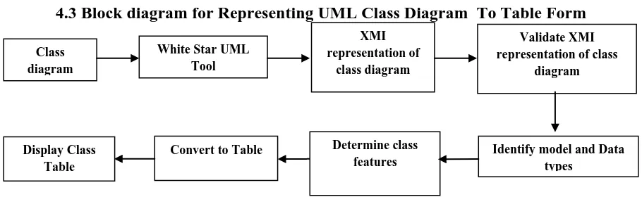
[image:2.595.70.525.309.449.2]4.3
Block diagram for Representing UML Class Diagram To Table Form
Figure 1: Block diagram of a procedure to convert from XMI form a of class diagram to class Table.
The above block diagram shows the procedure to convert UML class diagram to Table form. Initially a class diagram is drawn using White star UML tool and is exported to XMI form. This equivalent XMI class form is given as input to our proposed tool (Class Table Generator). Our proposed tool
validates the XMI tags and identifies the class features. The class features such as class name, attributes, visibility, multiplicity, association, generalization etc are abstracted. The abstracted information of class is mapped and is displayed to a Table form.
4.4
Algorithm
for
Representing
Class
Diagram To Table Form
INPUT: UML-Class-Diagram OUTPUT: Class-Table
Pre-Condition: A UML Class diagram Post-Condition: A valid XMI of Class diagram
REPRESENTING-CLASS-DIAGRAM (File-Name.xml) STR[1..n] ← File-Name.xml
if (! (Validate (STR [1..n]))) then return InValid xml else
Initialize Count= 0
for j ← XmlNode to xcontentnode do if Name == uml.model then
ChildNode ← NameSpace.ownedElement Count++
if ChildNode && Count > 0 then model ← childNode
while (model)
Identify class and class features for Class-j ← 1 to n do Class-j ← class-Name
Class-j [1..n] = {Attr-j, type-j, visibility-j} Class-j [1..n] = {Oper-j, Para-j, visibility-j}
Class-j [1..n] = {Asso-Class-name-j, Asso-name-j, multi-j}
Class-j [1..n] = {Parent-Class-name-j, Sub-Class-name-j,Generaz-j,Aggreg-j,Compo-j}
end for end while end if end if end for end if
for Class-j ← 1 to n do
Class-Table [1..n] ← Class-j [1..n]
end for
Display Class-Table
XMI representation of
class diagram
Validate XMI representation of class
diagram
Identify model and Data types
Determine class features Convert to Table
Display Class Table Class diagram
5.
CASE STUDY
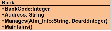
[image:3.595.63.274.238.298.2]The proposed procedure is implemented for various types of UML Class diagram and the results we got are correct and complete. The sample UML Class diagram Table 1 is the input and Table 2 is the output of our methodology. In Table 1 the UML class has three compartments which contain class name, attributes and operations. This Class has a class name as Bank and has two attributes named BankCode and Address with visibility public and data type as integer and string. The third compartment of class has two operations with visibility public. The first operation is named as Manages and has two parameters Atm_info and Dcard with datatype string and integer. The second operation is named as Maintains with null parameters.
Table 1: UML Class Diagram
Bank
+BankCode:Integer
+Address: String
+Manages(Atm_Info:String, Dcard:Integer)
+Maintains()
Step 1:
The first step of our proposed work is to export UML Class diagram to XMI form using White Star UML Tool. The following XMI code is generated by White Star UML for an UML Class diagrams Table 1.
<?xml version = "1.0" encoding = "UTF-8"?>
<XMI xmi.version = "1.1" xmlns:UML="href://org.omg/UML/1.3" timestamp = "Sat Mar 24 9:18:46 2018">
<XMI.header>
<XMI.documentation>
<XMI.owner></XMI.owner>
<XMI.contact></XMI.contact>
<XMI.exporter>StarUML.XMI-Addin</XMI.exporter>
<XMI.exporterVersion>1.0</XMI.exporterVersion>
<XMI.notice></XMI.notice>
</XMI.documentation>
<XMI.metamodel xmi.name = "UML" xmi.version = "1.3"/>
</XMI.header>
<XMI.content>
<UML: Model xmi.id="UMLProject.1">
<UML: Namespace.ownedElement>
<UML: Model xmi.id="UMLModel.2" name="Scenarios"
visibility="public" isSpecification="false"
namespace="UMLProject.1" isRoot="false" isLeaf="false"
isAbstract="false"/>
<UML: Model xmi.id="UMLModel.3" name="Logical View" visibility="public” isSpecification="false" namespace="UMLProject.1" isRoot="false" isLeaf="false" isAbstract="false">
<UML: Namespace.ownedElement>
<UML: Class xmi.id="UMLClass.4" name="Bank" visibility="public" isSpecification="false" namespace="UMLModel.3" isRoot="false" isLeaf="false" isAbstract="false" isActive="false">
<UML: Classifier.feature>
<UML: Attribute xmi.id="UMLAttribute.5" name="BankCode" visibility="public" isSpecification="false" ownerScope="instance" changeability="changeable" targetScope="instance" type="X.17" owner="UMLClass.4"/>
<UML: Attribute xmi.id="UMLAttribute.6" name="Address" visibility="public" isSpecification="false" ownerScope="instance" changeability="changeable" targetScope="instance" type="X.20" owner="UMLClass.4"/>
<UML: Operation xmi.id="UMLOperation.7" name="Manages" visibility="public" isSpecification="false" ownerScope="instance" isQuery="false" concurrency="sequential" isRoot="false" isLeaf="false" isAbstract="false" specification="" owner="UMLClass.4">
<UML: BehavioralFeature.parameter>
<UML: Parameter xmi.id="UMLParameter.8" name="Atm_Info" visibility="public" isSpecification="false" kind="in" behavioralFeature="UMLOperation.7" type="X.16"/>
<UML: Parameter xmi.id="UMLParameter.9" name="Dcard" visibility="public" isSpecification="false" kind="in" behavioralFeature="UMLOperation.7" type="X.17"/>
</UML: BehavioralFeature.parameter>
</UML: Operation>
<UML: Operation xmi.id="UMLOperation.10" name="Maintains" visibility="public" isSpecification="false" ownerScope="instance" isQuery="false" concurrency="sequential" isRoot="false" isLeaf="false" isAbstract="false" specification="" owner="UMLClass.4"/>
</UML: Classifier.feature>
</UML: Class>
</UML: Namespace.ownedElement>
</UML: Model>
<UML:
Model xmi.id="UMLModel.11" name="Development View" visibility="public" isSpecification="false" namespace="UMLProject.1" isRoot="false" isLeaf="false" isAbstract="false"/><UML: Model xmi.id="UMLModel.12" name="Process View" visibility="public" isSpecification="false" namespace="UMLProject.1" isRoot="false" isLeaf="false" isAbstract="false">
<UML: Namespace.ownedElement>
<UML: ActivityGraph xmi.id="UMLActivityGraph.13" name="ActivityGraph1" visibility="public" isSpecification="false" context="UMLModel.12">
<UML: StateMachine.top>
<UML: SimpleState xmi.id="UMLCompositeState.14" name="TOP" visibility="public" isSpecification="false" stateMachine="UMLActivityGraph.13"/>
</UML: StateMachine.top>
8 </UML: Namespace.ownedElement>
</UML: Model>
<UML: Model xmi.id="UMLModel.15" name="Physical View" visibility="public" isSpecification="false" namespace="UMLProject.1" isRoot="false" isLeaf="false" isAbstract="false"/>
<UML: DataType xmi.id="X.16" name="string" visibility="public" isSpecification="false" isRoot="false" isLeaf="false" isAbstract="false"/>
<UML: DataType xmi.id="X.17" name="Integer" visibility="public" isSpecification="false" isRoot="false" isLeaf="false" isAbstract="false"/>
<UML: DataType xmi.id="X.20" name="String" visibility="public" isSpecification="false" isRoot="false" isLeaf="false" isAbstract="false"/>
</UML: Namespace.ownedElement>
</UML: Model>
<UML: TaggedValue xmi.id="X.18" tag="ordering" value="unordered" modelElement="UMLAttribute.5"/>
<UML: TaggedValue xmi.id="X.19" tag="ordering" value="unordered" modelElement="UMLAttribute.6"/>
</XMI.content>
</XMI>
Figure 2: XMI representation of Table 1 exported from White Star UML
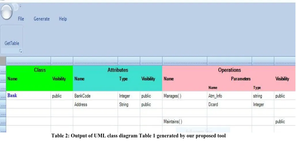
Step 2:
[image:4.595.57.571.304.551.2]In this step the required contents of an UML class diagram are abstracted from the XMI format and represented in form of a table by our proposed tool. Table 2 is generated output and is equivalent to Table 1 which contains all the class features and is analogous to matrix.
Table 2: Output of UML class diagram Table 1 generated by our proposed tool
6.
CONCLUSION
In this paper an attempt is made to represent the UML Class diagram into its equivalent table format.
The paper proposed a semi automatic tool which takes the UML class diagram as an input and then generates the output in a table format. This Representation of UML class diagram is carried out by converting class diagram into its equivalent XMI format and then abstracting the information from XMI and is presented in a table format. This tool collates all the UML class standard features such as attributes, operations, Associations, generalizations, Aggregation and composition which systematizes with no ramifications. It helps to quickly visualize relationships of class diagram and is affable to develop software systems and further may be used to abstract requirement specification. In future we are proposing similar kind of representation to the remaining UML diagrams.
7.
REFERENCES
[1] “OMG Unified Modeling Language TM (OMG UML),
superstructure version 2.2”,
http://www.omg.org/spec/UML/2.2/ Superstructure.
[2] Dr. R.N. Kulkarni, T. Aruna, and N. Amrutha, A. Mantri et al. “Abstraction of Design Information from Procedural Program” (Eds.): HPAGC 2011, CCIS 169, pp. 364–372, 2011. © Springer-Verlag Berlin Heidelberg 2011.
[4] B. Rumpe, “Modeling with UML”, Springer International Publishing Switzerland 2016, DOI 10.1007/978-3- 319- 33933-7_2
[5] Dr. R N Kulkarni, Nidhi Jain C, Rashmi G, Vaishali B J, Zakiya Niyazi, “Abstraction Of Test Cases From Input Java Program”, International Journal of Combined Research & Development (IJCRD) eISSN:2321-25X;pISSN:2321-2241 Volume: 4; Issue: 5; May -2015.
[6] Dr. R N Kulkarni “Abstraction of Uml Diagrams from Java Code “, International Journal of Combined Research & Development (IJCRD) eISSN: 2321-225X; pISSN: 2321-2241 Volume: 2; Issue: 4; April-2014.
[7] Dr. Shivanand M. Handigund, Rajkumar N. Kulkarni “An Ameliorated Methodology for the design of Object Structures from legacy „C‟ Program”, ©2010 International Journal of Computer Applications (0975 – 8887) Volume 1 – No. 13.
[8] Hicham Elasri and Elmustapha Elabbassi and Abderrahim Sekkaki and Muhammad Fahad, “Integration of UML class diagram with semantic Validation on segments of mappings”, CoRR, year 2018, volume abs/1801.04482.