Analysis of Shunt Active Filter with ANN based
Controller
Munazama Ali
Dept. of EEE Islamic University Jammu and Kashmir, IndiaDeeraj Joshi,
PhD Dept. of EEE Dehli Technical UniversityNew Dehli, India
ABSTRACT
Due to enormously increasing of power electronic devices such as arc furnaces,rectifiers,variable frequency drives introduces harmonics in the power system this leads to very low power factor in the power system. Power filters are widely used in modern electrical distribution systems to eliminate harmonic associated with it. This paper represents the effective solution of shunt active power filter to eliminate the harmonics associated with the utility power supply. The ShAPF requires accurate control algorithm that provides robust performance under source and load unbalances thus, compensation of harmonics depends largely on the algorithm adopted.
In this work both PI and ANNcontroller are used in three-phase shunt active power filter to compensate harmonics and reactive power by nonlinear load to improve power quality is implemented for three-phase three wire systems. ANN-based technique is implemented in shunt active power filters to produce controlled pulses required for IGBT inverter. Simulation result obtained shows that performance of ANN controller found is better than PI controller.
Keywords
Shunt Active Power Filter(ShAPF), Passive filters, Hysteresis current controller, control strategy, PI controller, Ann controller.
1.
INTRODUCTION
In recent years due to the development of power electronic devices, power electronic devices are evolved a lot and it will go on. The percentage is estimated to reach 60% to 80% by the year 2020. Any power problem that is due to voltage, current or frequency deviation that results in failure or disoperation of customer equipment or produces negative impact on the environment defines power quality. These power electronic devices draw non-sinusoidal currents on the load side. Due to these harmonics source will become non-linear. These harmonics involves many losses in the power system. It also results in the failure of customer requirement. Poor quality of power results in lost productivity, damaged equipment and early failure of equipment. As a result compensating devices are becoming very essential for the customer utilities. Non-linear loads like variable speed drives, electronic force supplies, arc furnaces are the major causes of power quality problem. These linear devices creates non-linear load for which applied voltage is not directly proportional to current. For these loads when voltage is purely sinusoidal still then current is distorted. Current harmonics results in many problems such as low power factor, low efficiency, power system voltage fluctuations and communication interference. These harmonics causes additional losses like overheating and overloading. A lot of conventional solutions are improvised to these problems.
Traditional solution for these problems are passive filtering. Due to their easy design, simple structure, low cost and high efficiency but use of inductor and capacitor makes the filter bulky. Also it causes resonance problem, large size, fixed compensation and possible overloads. Therefore the conventional passive filter cannot provide complete solution.
The development in the technology of power eletronics also spurred active power filter. Basic principle is that using power electronic devices cancels the harmonic currents from non-linear loads. An analogy electronic filter is combined with the active components like opamp, PWM Controllers etc. defines the Active power filter. A filter is designed which leads to the improvising of the performance and also this improves the reliability of the filter. Active power filter have been presented as a current compensator for reducing the total harmonic distortion of the current and correcting the power factor of the input source.
Various topologies of Active power filter has been developed so far. The shunt active power filter is a method of removing harmonics by supplying the harmonic current to the load in opposite direction to that of supply from mains. Here the principle operation of shunt active power filter is to generate compensating currents that the load needs and has a phase shift of 180 into the power system. Because of which the harmonic currents are cancelled that from the supply mains and from the filter. Due to which the mains current becomes purely sinusoidal. At present, calculation of the magnitude of the compensating currents of an active power filter is based either on the instantaneous real and reactive power of the non-linear load. Conventional PI Controller was used for the generation of a reference currents templates. The PI Controller requires precise mathematical models, which are difficult to obtain and fails to perform satisfactorily under parameter variations, nonlinearity, load disturbances etc. To improve the performance of shunt active power filter AAN Controller is considered to be a new tool to design shunt active power filter control circuitry because of its learning ability, high speed recognition and able to adopt themselves to any system.
2.
ACTIVE POWER FILTER
power compensation in power transmission systems. Active power filter can be implemented as:
2.1
Shunt Active Power Filter
Shunt Active power filters compensate load current harmonics by injecting equal but opposite harmonic compensating current in the load with a phase shift of 180 . Due to which the harmonic currents are cancelled that form the main supply and from the filter as a result the main current becomes pure sinusoidal.
2.2
Series Active Power Filter
The series active power filter is connected in series with the utility, it acts as a voltage source and also it isolates the harmonics from the non-linear load to the system. When there is poor supply voltage quality it prevents the equipment from being damaged. It also prevent the unbalanced voltage system, so it is controlled to eliminate voltage harmonics and regulates the terminal voltage of the load or line. In other way, a series active power filter acts as a controlled voltage source so that it supplies the harmonic voltage components in series with the mains and thus compensates the voltage sags.
2.3
UPFC(unified power flow control)
is a filter that combines a shunt and a series active filters. It acts as a controller for both voltage and current harmonics cancellation.
2.4
HAPF(hybrid active power filter)
Hybrid active power filter area a combination of active and passive filters. It has been proposed to overcome the disadvantages of APF and HPF. Appropriate choice of passive filters and detailed design method which when combined with APF will eliminate higher order harmonics. This improves the filtering performance and also cost effective.
3.
SHUNT ACTIVE POWER FILTER
The shunt active power filter is a recently developed piece of equipment that are connected in parallel with non-linear load.Need of the Shunt active power filter is due to the harmonics injected in power system due to the non-linear loads such as uninterrupted power supply(UPS), adjustable speed drives, arc furnaces etc. The shunt active power filter operates as a current source and generates the same amount of harmonics as generated by the load but 180 phase shifted.The shunt active power filter has a self-controlled DC bus that are used for reactive power compensation in power transmission system.Shunt active power filter has a better dynamic performance and it needs an accurate control algorithm that provides robust performance. The control methods are responsible for generating the reference currents which are used to trigger the voltage source inverter(VSI).It has been used to:
Eliminate current harmonics
Balance and regulate terminal voltage of load/line.
Reduce negative sequence voltage.
3.1
Basic Compensation Principle
The shunt Active power filter has a topology similar to that of STATCOM used for reactive power compensation.The shunt active power filter is controlled to deliver compensating currents to the load to eliminate current harmonics and thereby making the source currents in phase with source voltage.
Fig1: Shunt Active power filter scheme
Figure1,above shows the basic compensation principle of the shunt active power filter. It serves as an energy stored element and bring the real power difference between the load and source during the transient period. When the load condition changes the real power balances between the mains and the load will be concerned. This real power distinction is to be compensated by the dc capacitor. The change in capacitor voltage may result in ripple voltage of the dc capacitor. A low pass filter is generally used to filter these dc capacitor ripples. To avoid the use of low pass filter the capacitor voltage is sampled at the zero crossing of the source voltage.
To ensure that the compensating current drawn by the converter is smooth currents, an inductor is required to filter out the switching ripple current. For a good dynamic response, the size of this inductor must be as small as possible.
3.2
Estimation Of Reference Source
Current
From figure 1,the instantaneous current can be written as
= - (3.1.1)
Source voltage is given as
= (3.2.2)
If a non-linear load has applied, then the load current will have a fundamental component and harmonic components that can be represented by
= )
= + (3.2.3)
The instantaneous load power can be given as
*
t*+ sin t*cos t*sin + sin * (
n t+
= + (t) + (t)(3.2.4)
From (3.2.4), the real (fundamental) power drawn by the load is
(t) = t*cos = (t)* (t)(3.2.5)
(t) = (t) / (t) = cos sin t = sin t(3.2.6)
Where = cos
There are also some switching losses in the PWM converter, and hence the utility must supply a small capacitor leakage and converter switching losses in addition to the real power of the load. The total peak current supplied by the source is therefore
= + (3.2.7)
If the active filter provide total reactive and harmonic power. At this time, the active filter must provide following compensation current:
= (t) - (t)
Hence, for accurate and instantaneous compensation of reactive and harmonic power it is necessary to estimate, i.e.fundamental component of the load current as the reference current.
3.3
Control Strategy
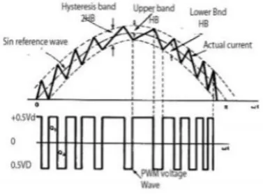
In anyactive power filter, control algorithm has major role in deciding the performance of harmonic compensation. Better control strategy leads to better dynamic response of the system. In this research work, control strategy is provided by hysteresis-band controlled technique.Hysteresis-band is basically an instantaneous feedback current control technique of PWM. The hysteresis band current controller for active power filter is used to generate the switching pattern of inverter. The control circuit generates the sine reference current wave of desired magnitude and frequency and it is
[image:3.595.71.260.435.574.2]then compared with actual current wave.
Fig 2: Hysteresis current controller
From the figure 2,above as the current exceeds an upper hysteresis band, the upper switches in half bridge is turned off and lower switch is turned on. As a result, the output voltage transition from and , and the current starts to decay. In same way, as current crosses the lower band limit, the lower switches are turned off and theupper switches are turned on. Hysteresis control method is proven to be best among the other control methods because of quick current controllability, easy implementation and unconditioned stability.
4.
ANN CONTROLLER SCHEME
Performance of shunt active power filter is determined by the accuracy and precision of harmonic components extracted from distorted current waveform. Shunt active power filter control algorithm has been developed in order to obtain best
performance to eliminate harmonic components of current or voltage waveform. Generally, Conventional PI Controller is used to regulate this voltage but due to its limitations, as the detection of PI parameters are difficult and time taking process also other disadvantages like inability to improve the transient response of the system therefore ANN controller has been introduced in this research work because of its learning ability, high speed recognition and able to themselves to any system. An artificial neural network(ANN), is a mathematical model inspired by biological neural network. Artificial neural network consists of an interlinked collection of artificial neurons and it develops information using a connectionist method to calculation. it resembles the brain in two factors:
(i) The data is accumulated by the network through the learning process.
(ii) Interneuron connection strengths are used to store the data.
The large data of the DC-link voltage for ‘n’ and ‘n-1’ intervals from the conventional method are gathered and are stored in the MATLAB workspace. This data is then retrieved and used for training the ANN Controller. The neurons in the input and output layer is almost a fixed quantity to obtain the provided input. At each training session, seven hidden layers are taken with 1000 iterations are done and six such a validation checks are taken out in order to minimise the scope of error occurrence.
The rapid spotting of the disturbing signals with high accuracy, and fast processing of the reference signals, are the prerequisites for desired compensation in caseof ShAPF.
5.
PERFORMANCE EVALUATION
Fig3:Simulation model of Shunt Active Power Filter(SAPF).
The performance of shunt connected active power filter has been evaluated in MATLAB. In this research work, source current is taken as an output. The value of THD is very high as no control circuitry has introduced for harmonic compensation in the three phase three wire system. After introducing Shunt active power filter to the same three phase three wire system with two different controllers separately, Total harmonic distortion (THD) is very much reduced.
Table1:Shows with THD with different values of various loads.
The shunt active power filter is switched to system at 0.02 sec. The response of switching before and after can be easily distinguished from the wave form and THD are given in figures below.
Fig4: Waveform of Three phase source currents without active filter.
Fig5: Harmonic spectrum without active filter.
(a)
(b)
(c)
Fig6: Three phase balanced (a) source current (b)SAPF Injected current (c) DC link voltage with PI Controller.
Fig7: Total Harmonic distortion with PI Controller.
(a)
(b)
(c)
Fig9: Total Harmonic distortion with Ann controller.
6.
CONCLUSION
In this work, it has been observed that shunt active power filter has eliminated current harmonics and reactive components of load current. The PI and ANN Controller are developed and verified for three phase three wire system. In this work it has been observed without any control circuitry the THD is very high around 18.79%. with conventional PI Controller it is reduced to 3.06% and with ANN Controller it is further reduced to 2.39% The performance of both PI and ANN Controller has been studied and compared in MATLAB.Both the PI and ANN Controller are capable of compensate line current harmonics. It has been seen that with ANN controller the THD is very much reduced then with conventional PI Controller.
7.
REFERENCES
[1] N. ramchandra, M.kalyanchakravarthi, “neural network based unified power quality conditioners”, International journal of Modern Engineering Research(IJMER) www.ijmer.com Vol.2, Issue. 1, jan-Feb 2012 pp-359-365ISSN: 2249-6645, 2012.
[2] Yash Pal , A. Swarup , and Bhim Singh, “Applications of APF for Power Quality Improvement” IEEE Transactions On Power Systems conference, December, 2010.
[3] MunazamaAli,arminderkaur and Abdul hamidbhat“comparative Analysis of shunt active power filter with pi and Ann controller”, International journal of computer applications(1-6, August) 2016.
[4] H. Rudnick, J.Dixon and L.Moran, “Active power filters as a solution to power quality problems in distribution networks,” IEEE Power and Energy Magazine.
[5] Elsa Susan Daniel and G.Abirami “Selective Harmonic Elimination Using Shunt Hybrid Active Power Filters Operating At Different Switching Frequencies” International Journal of Innovative Research In Electrical & Electronics, Instrumentation And Control Engineering Vol. 1, Issue 1, April 2013
[6] Chennai Salim and Benachaiba Mohamed Toufik,“ Three-phase three-level (NPC) Shunt Active power Filter
performance based pwm and Ann controllers for Harmonic Current compensation”, International journal on Electrical Engineering and informatics volume6,2014.
[7] Aziz Boukadoun, TaharBahi, AblaBouguerne, YoucefSoufi, SofianeOUdine, “ Hysteresis Band Current Fuzzy Logic Control for active power filter”, Eighth International conference and exhibition on Ecological Vehicles and Renewable Energies (EVER), 2013.
[8] Active power filter for reactive power compensation and Harmonic suppression by Hurng-Liahng job.
[9] T.Mahalekshmi “Current Harmonic Compensation and Power Factor Improvement by Hybrid Shunt Active Power Filter” International Journal of Computer Applications (0975 – 8887) Volume 4 – No.3, July 2010.
[10] BrahimBerbaoui, ChellaliBenachaiba and rachidDehini, “ Design of optimal PI controller for shunt Active Power Filter using particle Swarm Optimization”, Quatrieme Conference international surle genie Electrique CIGE’ 10, University deBecharAlgerie, 2010.
[11] Rachiddechini, Abdesselam bassou,Brahimferdu, “ Theharmonics detection method based on neural network applied to harmonics compensation”, International journal of engineering, science and technology, vol.2 , pp.258-267,2010.
[12] S. Jain, P. Agarwal, and H. O. Gupta, “Design simulation and experimental investigations on a shunt active power filter for harmonics and reactive power compensation,” Electrical Power Components and Systems, vol. 32, no. 7, Jul. 2003, pp. 671–692.
[13] F. Zahira, a. peer Fatima, “A technical survey on control strategies of active filter for harmonic suppression”,ICCTS, 2012.
[14] B. Singh, V. Verma, and J. Solanki, “Neural network-based selective compensation of current quality problems in distribution system,” IEEE Trans. Ind. Electron., vol. 54, no. 1, pp. 53–60, Feb. 2007.
[15] Simulink–Model-Based and System-Based Design, Modelling, Simulation,Implementation version 5,TheMathnWorks, July 2002.
[16] Joao L afonso, H J Ribeiro Silva, Julio, S Martin, “Active Filter For Power Quality Improvement”2001 IEEE Porto Power tech, 10-13 set, 2001 Porto Portugal.
[17] A. E. Emanuel, “Summary of IEEE Standard 1459: definitions for the measurement of electric power quantities under sinusoidal, nonsinusoidal, balanced, or unbalanced conditions,” IEEE Trans. Ind. Appl., vol. 40, no. 3, pp. 869–876, May/Jun. 2004.
[18] MetinKesler and EnginOzdemir, “Synchronous-Reference Frame-Based Control Method for SAPFUnder Unbalanced and Distorted Load Conditios”, IEEE transactions on industrial electronics, VOL. 58, NO. 9, SEPTEMBER 2011.
[19] R Rajalakshmi, Dr V Rajasekaran, “Improvement of Energy Efficiency through power quality by compensation of harmonics with shunt active power filter”2011 International Conference advancements in electrical, electronics and control engineering IEEE.
compensation in unbalanced /distorted electrical power system. 14th PSCC, Sevilla. 2002.
[21]Agelidis, V.G., "Real-Time Power System Phasors and Harmonics EstimationUsing a New Decoupled Recursive-Least-Squares Technique for DSPImplementation," IEEE Transactions on Industrial Electronics, vol.60, no.6,pp.2295,2308, June 2013.
[22]Elsa Susan Daniel and G.Abirami “Selective Harmonic Elimination Using Shunt Hybrid Active Power Filters Operating At Different Switching Frequencies” International Journal of Innovative Research In Electrical & Electronics, Instrumentation And Control Engineering Vol. 1, Issue 1, April 2013.
[23] M. Aredes, H. Akagi, E. H. Watanabe, E. V. Salgado, L. F. Encarnação, “Comparisons Between the p–q and p– q–r Theories in Three- Phase Four- WireSystems,” IEEE Transactionson Power Electronics, , vol. 24, no. 4,924933, April 2009.
[24] B.Singh,V.Verma, and J.Solanki, “Neural network-based selective compensation of current quality problems in distribution system,” IEEE Trans. Ind. E