http://dx.doi.org/10.4236/ojg.2012.23020 Published Online July 2012 (http://www.SciRP.org/journal/ojg)
Macroscopic Young’s Elastic Modulus Model of Particle
Packing Rock Layers
Cheng-Yao Guan1*, Jia-Fu Qi1, Nan-Sheng Qiu1, Guo-Chun Zhao2, Qiao Yang1, Xiang-Dong Bai3, Chao Wang1
1State Key Laboratory of Petroleum Resources and Prospecting, China University of Petroleum, Beijing, China 2The College of Geosciences and Resources, China University of Geosciences, Beijing, China
3Institute of Disaster Prevention, Sanhe, China Email: *[email protected]
Received May 21,2012; revised June 15, 2012; accepted June 23, 2012
ABSTRACT
Based on the Hertzian granular contact mechanics model, the paper built up a Macroscopic Young’s Elastic Modulus of particle/granular packing rock layers, and built up a ties to connecting Young’s Elastic Modulus of sand particle in Meso and the Macroscopic Young’s Modulus of granular packing rock layers. The Macroscopic Young’s Modulus of granular packing rock layers is far less than the Young’s Modulus of sand particle. The Macroscopic Young’s Modulus of granular packing rock layers is proportioned to the powers of 1/3 of the vertical contact force of sand particles. The Macroscopic Young’s Modulus is inversely proportional to particle diameter. The paper calculated the vertical contact force of five types aligning mode of the particles. When equal stress, the increased of the coordination number lead to the decrease of the contact force fn, this lead to the coordination number is an inverse proportion to Macroscopic
Young’s Modulus. But the larger coordination number change only means very little Macroscopic Young’s Modulus change.
Keywords: Particle Contact; Macroscopic Young’s Modulus; Arrangements of Particle
1. Introduction
Young’s Modulus of rocks or soil is the important pa-rameters in calculating seismic velocity, liquefaction of sand-soil, seismic exploration and hydrocarbon predic-tion, earthquake engineering, tunnel excavating, defor-mation of sand body, dynamic diagenesis of sandstone. Scholars always study the macroscopic structure of po-rous media used the relation of wave velocity and density of material experientially. But there was a positive cor-relation between wave velocity and Young’s Modulus theoretically and this logical accords with the principle of wave propagation. The difference between experiential methods and theoretical methods make the engineering application method and entirely pure research model each go its own way. Young’s Modulus obtained by ex-periment mostly. But few studies focused on Young’s Modulus of granular mixtures or granular packing rock layers. Liu Xu (2002) [1] used multi-phase medium mi-cromechanical model to educe out some macroscopic elastic parameter. But Liu’s method was based on most hypothesis on factor of porosity [2]. Zhong Xiao-xiong
(1992) [3] set up the relationship between fabric tensor and contact density distribution functions, and the rela-tionship between fabric tensor and stress tensor are ana-lyzed. Those model on stress tensor and arrangements of particle is too fussy to used on geologic and macroscopic mechanics of rocks and soils.
The Macroscopic Young’s Modulus of dry particle or granular packing rock layers is an important method to distinguish elastic deformation and plastic deformation of sedimentary rock layer. “From a grain sand can we find a world?”. The paper effort to set up a ties model between the macroscopic elastic parameter of granular packing rock layers and the elastic parameter of those sand particles. And effort to make out a series of simple theoretical logics and catch hold of those dominant fac-tors of those logics. Maybe this can help those investiga-tors and engineers to qualitatively and semi-quantitatively grasp the macroscopic elastic parameter of unconsoli-dated sandstone.
2. Model of Elastic Contact
1999 [5]; Sun Qi-cheng, 2009) [6] consider that the con-tact points transformed into interface after the elastic deformation. As Figure 1(a) shows.
The Hertzian contact theory as formula 1 to 7 shows. Among Figure 1, a is the round radius of the contact
interface and its distribution as Figure 1(b) shows. The
leads to normal displacements u over the contact area. The distribution of normal deformation amounts u of different spherical particles after the normal contact force fn. So, the deformation amounts of v of different
points in a contact interface as formula 3 shows. The
p r
is the relative approach of the centroids of the two sphere in contact.
21 2 2
r
u r u r
R
2
(1)
Among them,
1
(2)
1 2
1 1 1
R R
R (3)
2
2
1
1 2
1 1
1
E E
E
2
(4)
(a)
[image:2.595.59.286.251.687.2](b)
Figure 1. Hertzian contact model [5]. (a) Geometry of hert- zian contact between two dissimilar, unequal sized elatstic spheres subjected to an applied normal force; (b) Normal contact force distribution of Hertzian contact.
1 and 2 is the material’s Young’s Modulus of
spherical particles. and is the radius of particles 1 and particles 2, 1
E E
1
R R2
and 2 is the Max normal
de-formation amount of particles 1 and 2. So, the total nor-mal force is defined as formula 5.
3 2
14 3
n
f E R (5)
The inverse ratios of Normal Contact Stiffness Kn
can express the normal direction deformation amount between two particles center by unit normal direction force.
2 n
K E a (6)
Sun Qi-cheng [6] thought that if the normal deforma-tion amount is little, according to as formula 9, the force may be calculated by Hooke’s Law. And some studies looks the E in formula 6 as the Shearing
Young’s Modulus also mean a great errors.
3. Macroscopic Young’s Modulus
The Macroscopic Young’s Modulus is the Young’s Mo- dulus of particle packing rock layers. It is smaller than the material’s Young’s Modulus of spherical particles. Because of the different of material’s and rock layer’s, the wave velocity of various depth or petrofabric of rock layers is different. The percentage of sedimentary rock of the rock cover the earth surface was 75% and formed in sand particle packing layer. The compaction and dia- genesis in particle packing layer is also the process of pore evolution and change of Macroscopic Young’s Mo- dulus. Liu Yu (2010) [7] and Xia Tang-dai (2011) [2] put forward the concept of “effective shear modulus” and expression the relation between the material’s Young’s Modulus of spherical particles and the Macroscopic Young’s Modulus of particle packing layers. The “effec-tive shear modulus” has expression the macroscopic modulus partially but not considered the affect of diame-ters of the spherical particles in those papers. When we study the sand and soil then looks them as granular mix-tures, the “force chain” often as a important mechanism. The affect of the “force chain” is used in the lower stress and we should neglects it in the higher tension. We should attend to that the Ein formula 6 is only a
proc-ess parameters and a constant, not the real Young’s Mo- dulus of particle packing rock layers and no some good application meaning. In fact the Normal Contact Stiff-ness Kn is proportional to Macroscopic Young’s Modulus
g
E when only single contact point. The formula 5 be transformed into formula 7.
2 3
3 4
n f
E R
When we know the stress of external force which the particle packing rock layers suffered, calculating the de-rivative of the formula 7, My paper get the formula 8.
2 31 1
3 3
d 3 1
dn 4
n
f E
R f
1 (8)
The Macroscopic Young’s Modulus Eg as formula 9
shows.
21 1 3
3 3
d 4
d 3
n
g n
f E
E
R f (9)
The formula 9 is the theoretical Macroscopic Young’s Modulus for arbitrary spherical particles contact for small deformation respectively. If that is equal diameter, equal Young’s Modulus, equal Poisson’s Ratio spherical particles, formula 9 can be transformed into formula 10.
2 1
3 1
3 3 2
2
2 3 1
g n
E R
E f
(10)
From those component in formula 10, we can find that the theoretical Macroscopic Young’s Modulus of particle packing rock layers mainly be effected by following pa-rameters:
1) The material’s Young’s Modulus of spherical parti-cles. The theoretical Macroscopic Young’s Modulus of particle packing rock layers is proportional to the mate-rial’s Young’s Modulus of spherical particles and in-versely proportional to the material’s Poisson’s Ratio of spherical particles.
2) Eg is proportional to
1/3 n
f , so proportional to the
depth and stress and can not be calculated by Hooke’s Law.
3) The material’s Young’s Modulus of spherical parti-cles also be affected by temperature and pressure. Such as the material’s Young’s Modulus of sand particles (quartz) in the sandstone will decrease with higher tem-perature.
4. How the Arrangements of Particle
Affected
In the unconsolidated sandstone formation, the normal contact external force fn of equal diameter spherical
par-ticles is related to the corresponding depth, principal stress, diameter of particles. The fn is the forces be
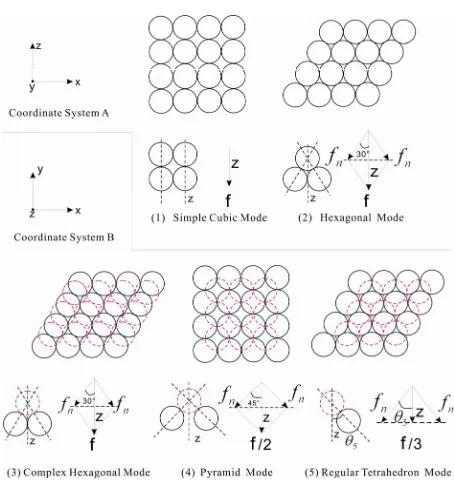
de-composed by f in the Figure 2. Their has five types
fa-miliar arrangements modes of particles [6,8], their names and coordination number as Table 1 shows and their
figures of modes shows as Figure 2. The particle
pack-ing rock layers tend to transform to make the direction of
the direction of the maximum principal stress 1
Max ability of resistance contact force consistent with
(par-allel to Z-axis in Figure 2). We may begins th the
example that the v
wi
is the maximum principal stress
1
in a rock layer a fault basin. The in i is the angle
force-decomposition. The force-decomp sition of five types familiar arrangements modes as Figure 2 shows.
The relations between corresponding total normal con
of o
- tact force fn and 1 (parallel to Z-axis) of the particles
arrangements modes i as formula 11 shows. 2
4π
fm k Ri 1 (11)
i ni mi z
k k k ki (12)
That the relations between th M
e Macroscopic Young’s odulus Eg and 1 of the particles arrangements modes
i as formula 13 shows.
2 2
3 1
3 3 1 2
2
2 3 1
gi i
E R
E k
(13)
The is the coefficient that can tell the relations be i
k
tween maximum principal stress 1 and its corre-sponding normal contact force fni of a single particle
un-der the affect of the particles arrangements modes i. The kn is the area coefficient which express a single
particle undertake the stress/theoretical area. kni is the
area coefficient kn of the particles arrangements modes i.
Figure 2. Five types familiar arrangements modes of parti-cles (coordinate system B: The Z-axis perpendicular to the paper surface, 5arcsin
3 3
, (1) and (2) accord with [image:3.595.309.536.427.668.2]nge s come from reference
[image:4.595.58.539.111.263.2]Name of particles a
Table 1. Coefficients of the five types familiar particles arra ments modes (the data of N, hi, vrh wa
[6]).
i rrangements modes N Ne hi vrh i kni kmi kzi ki kti
1 Simple Cubic Mode 6 2 2R 8R 3 0˚ 1 1 1 1 1
2 (Trapezoid body) MHexagonal ode 8 4 3R 4 3R3 30˚ 1 3 3 1 3 3 2/3
3 Complex Hexagonal Mode 10 4 3R 6R3 30˚ 3 2 3 3 1 1 2 0.5773
4 Pyramidcubic) Mode (Face centered 12 8 2R 4 2R3 45˚ 1 2/2 2 2 4 0.5
5 Reg(Rhombic) Mode ular Tetrahedron 12 6 2 2 3R 4 2R3 arcsin 3
3 3 2 1.5 1 2 2
3 43 2 2
4 2
ni rhi i
k v R h (14) We can find that the f in Figure 2 acc
15
ord with formula .
1 ni
f k (15) The km is the coefficient whic
be
o the force de
h express contact angle tween the two layers particles, The kmi is the
coeffi-cient km of the particles arrangements modes i. The kz is a
coefficient which relate to the coordination numbers N. The vrhi is the undertake volume of a single particle of
the p cles arrangements modes i. The hi is the layer
height of the particles arrangements modes i. The kmi should be calculated according t
arti
composition angles i which based on the
decompo-sition principle for the rces. The decompodecompo-sition angles
i
fo
shows as Figure 2.
Besides the particles arrangements mode 1—the Sim-ple Cubic Mode, the kzi(kz2,kz3,kz4,kz5) should be
calculated according to t nation num-ber Ne(
he effective coordi 4
e
N N ).
Th e os coefficients o articles ar-ra
f the 5 types familiar p
ngements modes as the Table 1 shows. If we sum and
average the five types familiar particles arrangements modes simply. The sum and average can not representa-tive the fact on the particle packing rock layers. But in a larger scale, the five familiar particles arrangements modes must all exist and closer to the average. The sum and average not means a bigger error. From the Table 1,
the coordination number N1 and vertical Eg1(kt1) of
the Simple Cubic Mode is smallest and the bi st f the Regular Tetrahedron Mode. Not all the coordination number undertake the maximum principal stress 1
gge o
and the change of vertical Eg1(kt1) mild than the ch e of
the coordination numbe i
The model has not finished
ang
l in above r N .
. Because m pa
ode
ragraphs focused on the contact force fni which parallel
to the maximum principal stress 1. When the normal contact force fni not parallel to th maximum principal
stress 1
e
, we need to convert the normal displacements
to parallel to the maximum principal stress 1. So
the Egi transform into the formula 16.
2 2 3
3
2 13
1
2 2 cos
3 1
gi i i
E E R k
(16)
, if look the
So ki cosi in formula 16 as a t
k, then the kti shows as Table 1 m
five fam
o . If we su
tal co- efficient t
d average the iliar particles arrangements modes simply. Then the average kt must be (
an
t
k =
0.63538).
The formula 10 and the formula 16 is respectivel the Eg that expre
y and m ssed by normal contact force fni axi-m principal stress 1
mu . The formula 16 tell us that the Eg is proportional to R2/3.
Because differentiation of those material’s Young’s Modulus E of spherical particles is often not bi the
particle p ing g, but
ack diffe
lay
rentiation of the radius of particles R is often differ-ence by several magnitudes. So the R is often the princi-pal influencing factors of Eg and maybe lead to the Eg of
sandstone bigger than that of mud rock.
In populous sedimentary basin and its most sedimen-tary stage, for example the loose sand
ers in quaternary, in those layers, the principal stress in vertical direction v is the Max principal stress 1,
that is say that v parallel to Z-axis, the stress field is
express as vHh, the H is the Max horizontal
principal stress a the nd h is the Min horizontal prin-cipal stress. In those type stress field, v should be
provided by the gravity of erlying strata S.
v S pf r w gH
(17) ov
f
p is the pore fluid pressure, r is th
rical particles,
e bulk density of sphe w is the bulk density of pore fluid (often is water).
In practice, we can use the formula 17 to estimate the Max principal stress 1 in depth of H, then we
lu
5. Discussion
Young’s Modulus of quartz bulk parent rock is often 40 In fact the quartz bulk parent rocks is d its Young’s Modulus is less than that
h than several hundred mete so
nd h
dulus of particle packing rock layers an
GPa - 100 GPa. also have pore an
of material’s of spherical sand particles. Other material's Young´s Modulus of material’s has hardly been reported before. Because of the existing of some other mineral particles and clay particles, Young’s Modulus of mineral particles maybe less than the quartz mineral particles, but maybe not less than the quartz bulk parent rock. LiuYu (2010) [7] thought that 20 GPa - 80 GPa is a reasonable range of Young’s Modulus of mineral particles E. Some data from Tian Jia-ning (1988) [9] tell that those Young’s Modulus of rocks distributed from 5 GPa - 60 GPa and very discrete. Those Young’s Modulus of some rocks of clay particles is only 0.17 Ga, this less two magnitudes than that of sandstones, and maybe related to the spatial structure of those clay particles. Some shear wave veloc-ity of particles packing rock layers which not deep than 15 m is often only 60 - 200 m/s (Elnashai, 2008) [10] and far less than that of average value of sedimentary rock on the upper crust (2800 m/s - 3500 m/s), also less than the compressional wave velocity of water (1400 m/s). Some data from An-Ou (1992 [11]) also tell that the Young’s Modulus of rocks distributed from 0.1 GPa - 20 GPa and very discrete. Those bigger differentiation of Young’s Mo- dulus and wave velocity verify that the Young’s Modulus tend to approaching to zero when close to earth surface synchronously.
The former model on Macroscopic Young’s Modulus of particle packing rock layers is only suitable for the rock layers not dept rs or me loose sandstone with rapid sedimentation. Plastic deformation maybe the dominating mode of the change of Macroscopic Young’s Modulus of particle packing rock layers in a depth or an older stratum of rocks. In this paper, Eg is proportional to R2/3, but some data express
that is inverse proportion, for example An-Ou (1992: p. 34) [11], The paper think that because of those data was come from rocks in depth a ad undertake long-term plastic deformation and dynamic diagenesis. The plastic deformation velocity of little diameter particles is greater than that of the bigger diameter particles. The plastic deformation velocity model of particle packing rock lay-ers need to be developed. We should also attend to that the instantaneous Young’s Modulus will determine the plastic deformation velocity in a time future .The elastic deformation will runs through modern and the elastic deformation model will be the basement to distinguish the elastic deformation and plastic deformation.
6. Conclusions
1) The paper set up a model to calculate the
Macro-scopic Young’s Mo
d the model includes the model that can tell how the arrangements of particle affected.
2) Eg is proportional to
1/3 n
f and proportional to
1/3 1
, can not be calculated by Hooke’s Law. The Mac-roscopic Young’s Modulus of drysand particle packing
k layers which close to the earth surface is approach-ing to zero in 0 m depth, and the too little Macroscopic Young’s Modulus is the main cause of earthquake site effect.
3) roc
g
E is proportional to R2/3, the differentiation of
the radius of particles R is often difference by several ma itgn es. So the R is ofte e principal influencing factors of
ud n th
g
E .
4) When equal stress, the increased of the coordination number lead to the decrease of the normal contact force
n
f , this lead to the coordination number is an inverse
proportion to Macroscopic Young’s Modulus. But the larger coordination number change only means very little Macroscopic Young’s Modulus change.
REFERENCES
[1] X. Liu, “Elastic Parameters and Velocity Calculation in Multi-Phase M , Institute of Geo- physics, Beijin
hnology, Vol. 43, 2011,
l Engineering, Vol. 14, 1992, pp. 39-48.
. 1-127.
ydro Electric Power, Vol. 4, 1988, pp. 21-27.
aterials,” Ph.D. Thesis g, 2002, pp. 1-78.
[2] T.-D. Xia, Y. Liu, M. Wu, et al., “Shear Wave Velocity in
Deep Buried Sand Based on Spheres-Contact Theory,”
Journal of Harbin Institute of Tec
pp. 99-103.
[3] X.-X. Zhong and J.-X. Yuan, “Microfabrics and Constitu- tive Relations of Granular Materials,” Chinese Journal of Geotechnica
[4] K. L. Johnson, “Contact Mechanics,” Cambridge Univer-sity Press, Cambridge, 1985, pp. 91-104.
[5] M. Oda and K. Iwashita, “Mechanics of Granular of Granu- lar Materials: An Introduction,” A. A. Balkema, Rotter-dam, 1999, pp. 207-209.
[6] Q.-C. Sun, M.-Y. Hou, F. Jin, et al., “The Physical and
Mechanical of Granular Materials,” Science Press, Bei- jing, 2011, pp. 191-193.
[7] Y. Liu, “Research on Sand Shear Wave Velocity Based on Particle Contact Model,” Ph.D. Thesis, Zhejiang Uni- versity, Hangzhou, 2010, pp
[8] F. Zeng, et al., “Particle Technology of Mineral Process-
ing,” China University of Mining Press, Xuzhou, 2001, pp. 92-93.
[9] J.-N. Tian and H.-L. Shi, “Comparison and Experimental Study of Dynamic Elastic Modulus and Tatic Modulus,”
Journal of H
[10] A. S. Elnashai and L. D. Sarno, “Fundamentals of Earth- quake Engineering,” Wiley,Hoboken, 2008, pp. 28-29. [11] An-Ou, “Tectonic Stress Field,” Earthquake Publishing
![Figure 1. Hertzian contact model [5]. (a) Geometry of hert- zian contact between two dissimilar, unequal sized elatstic](https://thumb-us.123doks.com/thumbv2/123dok_us/9290952.425155/2.595.59.286.251.687/figure-hertzian-contact-geometry-contact-dissimilar-unequal-elatstic.webp)
![Table 1. Coefficients of the five types familiar particles arra[6]).](https://thumb-us.123doks.com/thumbv2/123dok_us/9290952.425155/4.595.58.539.111.263/table-coefficients-types-familiar-particles-arra.webp)
