© 2019, IRJET | Impact Factor value: 7.211 | ISO 9001:2008 Certified Journal
| Page 953
“Quality Control Measures and Strategies for Filament Wound
Composite Pressure Vessel for Space Application”
Sameerkant Behera
1, Lokesh Srivastava
2, C.H.Ugender
3, J. K. Mishra
4, A. S. Srinivasa Gopal
51, 2, 3, 4, 5
Advanced System Laboratory, A. P. J. Abdul Kalam Missile Complex, PO Kanchanbagh, Hyderabad,
Telangana, India
---***---Abstract –
Filament wound composite pressure vessel isbasically a high pressure container with integrated end domes and other specific load bearing attachment widely used for space application due to its high performance factor. In last decade, many open literatures have been available on design, development and qualification of composite pressure vessel. However no comprehensive work is available on implementation of quality control measures during design, manufacturing and testing to make consistent quality product with high order of repeatability. As product design, raw material characterization and process design goes hand in hand for composite, it calls for meticulous process planning, stringent quality control at each stage and reliable testing methodology for assessing structural integrity so as to declare a flight worthy product. This paper discusses an insight on various stringent quality control measures & strategies at each and every step progressing right from raw materials to in-process inspections during manufacturing and final product acceptance test. Also emphasis has been given on establishment of process parameters and their control which plays dominant role on end product quality. Challenges multifold due to lack of standards and non- availability of proven post corrective methods for any major non-conformance condition as available for metal processing. Six no’s of composite pressure vessels are realized implementing stated quality control methodology. Based on subsequent results of non-destructive and acceptance testing, a conclusion is arrived at on the effectiveness of quality control methodology to realize consistent quality products.
Key Words
:
Acceptance testing, Filament wound, Non-Destructive testing, Performance factor and Quality Control.
1. INTRODUCTION
Filament wound composite pressure vessels are high- pressure containers that are widely used as components of aerospace, hydrospace and military applications such as air bottles, pipe lines, rocket motor casings, helicopter blades, large storage tanks etc. [1]. Composite materials with their higher specific strength, specific modulus and strength tailorability c h a r a c t e r i s t i c s will r e s u l t i n reduction o f weight of the structure. The choice of composite as primary material in design and manufacturing of the pressure vessel
Is dictated by the fact that the performance factor (‘n’ = PV/W) is consistently higher for composite pressure vessel as compared to that of metallic counterparts [5]. Filament winding is an obvious choice to develop the pressure vessel as it provides an efficient netting system of fibers/roving, in which the benefit of variability of directional strength is utilized [3].
In last decade, several literatures have been available on design, development and testing of composite pressure vessel for space application. F. Betti et al. [1] discussed overview of the design, development programme and technology activities for simultaneous development of three new VEGA SRM composite cases. Michele Biagi and Alian Mauries [2] discussed details about full scale structural qualification test and final burst test which led to the pronunciation of final qualification of world’s largest composite case. M. Madhavi, K. V. J. Rao and K. Narayana Rao [3] developed methodology about design and analysis of filament wound composite pressure vessel with integrated domes. They also discussed about progressive failure analysis of composite pressure vessel with geodesic end domes including matrix crack failure, burst pressure value at various position of the shell. D. Cohen [4] provided insights on experimental design investigation of manufacturing & design variables that effect composite vessel strength and stiffness.
Sl. No. End Properties/ Testing
Specification
1 Proof Pressure
Testing To withstand proof pressure, Strain & dilation shall be less than design specified Value
2 NDT Free from defects &
cumulative
defective zone shall be less than 5 % of total scan area 3 Travel coupon properties
Resin content 30 – 40 %
Density 1.65±0.5
Tg 150 min
NOL Tensile
strength 1800 MPa (min)
2.
BRIEF ON CONSTRUCTION DETAILS AND
DESIGN
2.1. Construction Details
[image:2.596.36.291.268.390.2]The general architecture of composite pressure vessel used for space application is shown in Figure 1. It primarily consist of three sub-assemblies viz. (i) composite main casing which consists of cylindrical vessel closed with forward & aft end domes which sustain internal pressure (ii) Encapsulated end fittings which interface with other sub- systems (iii) aft end & fore end flange attachments to transmit thrust and interface with subsequent stages.
Fig – 1: General architecture of a typical composite pressure vessel
3.
QUALITY CONTROL METHODOLOGY
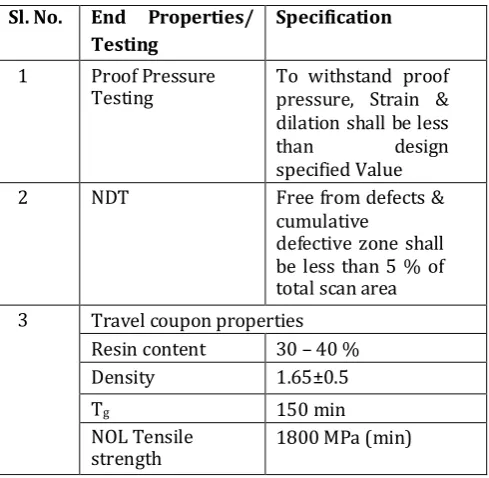
The key requirements of an aerospace system is to have use of light weight components which can be achieved through use of high specific strength and high specific stiffness material such as composites, complemented with low design factor of safety. At the same time, it also demands high reliability and robustness. All the above factors calls for implementation of stringent quality control inevitable at each stage of composite manufacturing. The whole objective of implementing the stated quality control methodology & strategies to achieve specified properties on end product which are mentioned in table 1. The whole approach of quality control measures and quality assurance strategies of composite pressure vessel primarily focuses on four important aspects: (i) Raw material control (ii) Tooling and equipment control (iii) Process control (iv) Product control which are discussed in detail in the following paragraphs.
Table - 1: End product requirement
2.2. Design
The design of composite structures, unlike that of metals, goes hand in hand with the design of material system and process. Hence, it is essential that the selection of materials along with its characterization and process design for various parts of the casing is done simultaneously. Composite pressure vessel is an axi-symmetric thin shell and during normal operating condition it is predominantly under tensile stress. These stresses vary along the axis of the casing [3]. The cylinder of filament wound pressure vessel basically comprises of helical and hoop layers whereas the end domes consists of both helical and doilies. Doily is a planar rei nf o rc em ent applied t o local a rea s to provide additional strength, usually in hoop direction. Since it is not possible to wind hoop layers on end domes directly by filament winding technique, an additional layer either a unidirectional fabric or drum wound hoop layers are developed and placed on the end domes. The plies are so arranged as to maintain symmetry with respect to mid - plane. A balanced symmetry is the best option for axi- symmetric structures because the loading in a particular plane will not cause deformations in other planes. It is always better to wind hoop and helical layer alternatively and hoop layer on outside so as to have better consolidation effect.
3.1. Raw Material Quality Control
[image:2.596.315.560.319.558.2]© 2019, IRJET | Impact Factor value: 7.211 | ISO 9001:2008 Certified Journal
| Page 955
Product level. Above requirements are essential as a given [image:3.596.36.284.225.460.2]batch of reinforcement and resin combination can give different properties depending upon the composite construction and fabrication process adopted. Additionally few quality control parameters also need to be checked as a part of batch acceptance. Quality control requirements followed for metallic and composite raw materials are given in next paragraphs.
Table - 2: Raw material system and process
Component Material Manufacturing mode Metallic end
fittings High Strength Al alloy Heat treated and Machining Bulkhead
flange High Strength Al alloy Heat treated and Machining Main casing
with skirt Carbon fiber with epoxy resin
Filament (wet) winding
(Helical, hoop winding and doilies)
Encapsulation of metal end fittings
Chemlok 205, nitrile based rubber solution
Rubber
layup/compression molding and curing
Metallic flange
joint Epoxy adhesive and composilok fastener
Bonding and Riveting with composite skirt
A. Metallic Material Batch Acceptance
Aft end, fore end metallic end fittings and metallic bulkhead flanges are made up of high strength Aluminum alloy as mentioned in Table 2. Above grade raw materials are accepted through satisfactory chemical, physical and mechanical properties compliance to relevant standard. Also other quality control parameters such as micro and macro inclusion rating, grain orientation are checked at billet and forging stages. Time temperature log, calibration of oven & related instruments are ensured to validate proper heat treatment as per established cycle. Presence of internal discontinuities are critically checked using Ultrasonic test at billet and ring forging levels. Final machined components have to undergo visual inspection, surface discontinuities by dye penetrant test and dimension inspection. One of the essential quality requirement of aluminum alloy machining is to follow multiple machining stages in phased manner followed by natural ageing after each machining stage so as to avoid any kind of distortion.
B. Composite Material Characterization
Higher strength carbon fiber and toughened epoxy resin with suitable hardener having longer gel time, longer pot life and better mechanical properties are selected for composite casing. The whole process of characterization is as follows:
I. Individual Constituent Level:
Carbon fibre, uncured epoxy and hardener are batch accepted through extensive testing of mechanical and physical properties. Carbon roving’s are tested for density, tex, tow size, diameter of filaments, carbon content, sizing for epoxy compatibility along with critical mechanical properties viz. impregnated tow tensile strength, hoop strength from Naval Ordnance Laboratory (NOL) ring and Interlaminar shear strength (ILSS). Epoxy resin is tested for specific gravity, viscosity, epoxide content, volatile content and hardener is tested for specific gravity and viscosity. Batch identification and shelf life of each individual constituent is required to be maintained throughout the manufacturing cycle. Understanding cure behaviour of thermo setting resin is essential in the development and optimization of composite fabrication process. The cure kinetics and rheological behaviour of cured neat resin were investigated by means of differential scanning calorimetry (DSC) and dynamic mechanical analysis (DMA). Optimum cure cycle was established based on fast, time and cost effectiveness out of different simulated cure cycles.
II. Laminate Level:
Flat plate laminates are made by filament winding technique on flat shaped mandrel using accepted batch of fiber & resin and subsequently cured as per established cycle. Specimens are derived from cured laminate to determine physical and mechanical properties. Physical properties viz. density and fiber volume fraction (Vf) and glass transition temperature (Tg) are evaluated. Considering
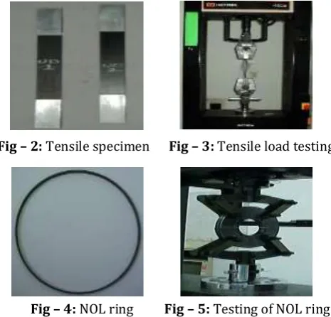
orthotropic plane stress condition, four independent elastic constants namely elastic moduli in longitudinal and transverse directions, in-plane shear modulus, major Poisson’s ratio and five independent strengths namely tensile and compressive strength in longitudinal & transverse directions, in-plane shear strength are determined. Figures 2 & 3 show tensile test specimen and its tensile testing in universal testing machine. Additionally quality control properties viz. flexural strength, flexural modulus, ILSS are also being measured for batch acceptance.
NOL ring samples are fabricated to measure hoop strength of carbon fiber and it is also made as a travel coupon during realization of pressure vessel as a tool of quality control. Figures 4 & 5 show NOL ring specimen and its tensile testing respectively. Results obtained from the above testing are compared with value considered as design input, if found satisfactory, then only each respective batch of raw material is qualified for its use in manufacturing. Each new lot of raw material is tested for individual constituent properties along with laminate level properties and NOL ring hoop strength for its acceptance & qualification.
III. Reduced Scale Product Level:
and same ply sequence preferably. Subsequently same is to be burst tested to know the failure mode and to estimate knock down factor. Otherwise a small pressure vessel can be made as per ASTM D2585 and burst tested to know fiber strength. For our development cycle, one full scale composite pressure vessel was realized and same was qualification tested i.e., structural load test and hydraulic burst test to validate raw materials, process design and product design.
Fig – 2: Tensile specimen Fig – 3: Tensile load testing
Fig – 4: NOL ring Fig – 5: Testing of NOL ring
3.2 Tooling & Equipment Control
Tooling plays a critical role in composite part manufacturing and facilitate manufacturing of accurate & repeatable part within the confines of process parameters. Following are tools/fixtures which are used for realization of composite pressure vessel made by wet filament winding.
a. Mandrel assembly for main composite casing. b. Moulds for metallic end fittings encapsulation. c. Add on composite skirt winding fixture. d. Metallic flange bonding fixture.
e. Central drive shaft pull-out fixture.
The selection and design of mandrel assembly is done in such a way to facilitate structural winding load and thermal expansion control along with production reusability, tolerance control, weight saving and easy extraction. Mandrel can be of collapsible, dissolvable, breakable etc. out of which breakable mandrel is considered for our study. Breakable mandrel assembly consists of a central steel shaft with a super structure of disc of rigid poly urethane foam and plaster of Paris. The foam discs are assembled on shaft, then machined to a lower profile, finally PoP is applied and machined to specified internal casing contour. This mandrel also provides features for holding metallic end fitting, add on skirt winding fixtures and metallic flange bonding fixture accurately. Different stages of mandrel assembly preparation is shown in figure 6. Foam disc are casted from specified proportion of Daltorim & Suprasec. Daltorim is a
[image:4.596.307.566.227.300.2]macro molecule of polyhydric alcohols with molecular weight from 2000 to 7000 with functionalities ranging between 2 & 8. The most commonly used iso-cyanate is a Surpasses and it is a modified form of MDI. These materials not only have a good resistance to burning and flame spread but also be able to withstand service temperatures of up to 150°C. As a part of quality control, sample representative from each batch of foam disc are tested for density, compressive strength and thermal resistance for its acceptance. Specified value for each properties are given in table 3.
Fig – 6: Mandrel assembly preparation
Table - 3: Acceptance criteria for foam disc
Sl. No Parameter Specified
Value
1. Density, Kg/m3 100 (Min.)
2. Compressive Strength, MPa 1.5 (Min.) 3. % Volume Change
after exposure to 150°C for 5 hours
5% (Max.)
All other tools/fixtures are inspected for critical dimensions, geometrical tolerances and profile contours along with final dry assembly/suiting for its final usability. The machinery/equipment’s required for realizing different parts and sub-assemblies are filament winding machine, hydraulic press, oven & other related instruments and Computer Numerical Control (CNC) lathe. Filament winding machine in the order of 4 or 5 Degree of freedom (DOF) is preferred. Calibration and validation of above equipment’s are ensured before start of the winding.
3.3 Process Control
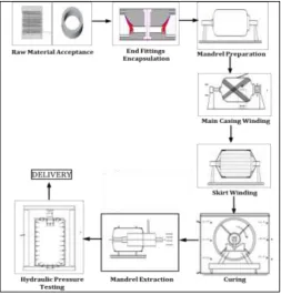
It is imperative to have tight control on process variable during wet filament winding so as to achieve defect free and acceptable flightworthy product within the constraints of manufacturing process. Figure 7 represent schematic of established manufacturing cycle for composite pressure vessel.
© 2019, IRJET | Impact Factor value: 7.211 | ISO 9001:2008 Certified Journal
| Page 957
g. Through Transmission Ultrasonic Test is performed tocheck interface integrity. Any kind of de-bond is not allowed between metal to rubber.
h. Shore D h a r d n e s s m e a s u r e m e n t o n c o m p o n e n t t o ensure proper curing.
[image:5.596.37.291.112.379.2]II. Main Casing Winding:
Fig – 7: Schematic diagram for manufacturing of composite pressure vessel
I. Metallic End Fitting Encapsulation:
Metallic end fittings are encapsulated with nitrile based rubber to accommodate differential deformation between metal and composite casing. Rubber is laid up on both internal and external surfaces of metal and subsequently moulded & vulcanized in compression mould using hydraulic press. Proper vulcanization of rubber, continued de-bond free interface, specified profile contour and thickness needs to be critically controlled for which following quality control is adopted.
a. Qualified encapsulation mould is used for compression moulding & qualified template is used for rubber cutting for layup.
b. Qualified rubber material used having valid shelf life. c. Surface preparation is done by abrading correct size of
sieve followed by application of primer such as chemlok keeping minimum of 4hrs for drying.
d. Rubber solution (mixture of Toluene + EDC + Rubber flakes in the ratio of 1kg: 1lt: 1lt) is used as adhesive between casing & rubber sheet.
e. It is ensured that established vulcanization cycle is used along with specified ply sequence & staggering of plies. f. Visual inspection is done to check encapsulated surface
is free from blow holes, pin holes, dry patches and inclusions.
Considering wet filament winding, helical winding together with hoop winding and doily layup technique is adopted for realization of main casing. In wet winding, the dry fiber/roving is passed through a resin bath causing resin impregnation and placed on the rotating mandrel in a predefined path. The critical process parameter are fiber tension, fiber wet-out , resin content, winding angle, winding time between layer, winding tension gradient, stacking sequence etc. which are to be tightly controlled. Following are the process control adopted.
a. Before start o f w i n d i n g , measurement o f a n g u l a r orientation between dowel holes of each metal end fittings so as to control orientation between two ends.
b. Measurement of distance between end to end metallic end fittings so as to control total length of the component.
c. Validation and verification of winding programme by trial winding and checked for start pattern and band width. Generally, 5 to 20 start pattern is preferred. d. Adequate fiber tension is required to maintain fiber
alignment on the mandrel, good compaction of fibers and to control resin content. Fibre volume fraction values (Vf) shows a strong correlation with the applied
winding tension. An increase in tow tension displaces more resin from within the fibre bed, which in turn accumulates on the outside of the part, thus the overall fibre volume fraction changed across the thickness. So fiber tension is given preferably within 1 to 4 N per end so as to maintain uniform Volume Fraction (Vf).
Measurement of fiber tension is usually done using tension meter.
e. Fiber wet-out is controlled by viscosity of resin system, number of strands, fiber tension, and speed of winding and length of resin bath. Good fiber wet out is essential for reducing voids in filament wound part. For a good wetting, the minimum length under the resin surface level is 15cm and a time period of 0.3 to 0.5 sec is chosen.
g. Resin content is controlled by proper wiping action at squeeze bar or stripped die, optimized fiber tension and a d e q u a t e r e s i n v i s c o s i t y . Also e x c e s s r e s i n i s squeezed out manually after each layer without disturbing the fiber pattern.
h. Specified Ply sequence must be followed and properly recorded. Alternate layer of hoop & helical is given with Hoop as top layer because hoop winding on outside gives better consolidation effect on helical fiber. If no hoop is placed inside the helical, then the helical tends to pull away from laminates.
i. It is preferably to shorten gap between two layers and to shorten total time required for winding. The winding time between layers effect hoop strength, longitudinal strength and fiber volume fraction. Shorter winding time produces higher fiber volume than longer winding time. Cylinders wound in a short time had on the average 6.3% thinner wall thickness relative to cylinders wound over long winding time [4]. Cylinders that were wound with short winding time exhibit less spring back than the cylinders wound with long winding time.
j. A change in winding angle may lead to stress carrying capability in a particular direction. To maintain specified winding angle, slackness between mandrel center and machine rotating center is controlled by calibrating the machine.
k. Fibre damage may occur due to fuzziness. The fibre breakage during winding can lead to a problem of keeping the filament integrity. The broken fibres tend to fall off, and the broken fibres accumulated in the resin bath can increase the viscosity of resin bath, making resin pickup uneven. Fiber Fuzziness is controlled to the maximum extent possible. Otherwise it can be cut wherever fuzziness observed in fiber strand.
l. Utmost care is provided while layup of circumferential segment of doilies. Doilies development is done using standard template and lay-up is done providing overlap of 25-50mm.
m. Adhesive used for bonding of metallic flange to composite skirt is qualified through testing for lap shear strength. Room temperature curable adhesive is generally preferred.
III. Curing
a. Filament w o u n d p a r t i s c u r e d a s p e r c u r e c y c l e established based on cure kinetics of resin system.
b. Travel coupon (NOL ring) is made using same process variable as filament wound component and cured along with final component, subsequently tested for physical, mechanical and thermal properties as mentioned in 3.1 B.
c. Two thermocouples are inserted at two ends of component between ply layers so as to measure component temperature. It is recommended to ensure
no significant difference between air and component temperature, preferably to limit within 10 °C.
d. Time temperature log book is recorded during curing to ensure proper curing.
3.4 Product Control
Product control essentially emphasize on evaluation and measurement of specified properties on end product. It is essentially achieved through visual inspection, dimensional inspection, non-destructive testing and evaluating properties on travel coupon representing final part.
3.4.1
Detailed metrology inspection is carried out onfinal product to measure all the critical dimensions & specified geometrical features. Some geometrical features such as concentricity of aft end metallic fittings and fore end bulkhead flange with respect to Aft end flange, parallelism of both bulkhead flange face etc. are critically measured within the tolerance limit of 0.5mm.
3.4.2
Specimen derived from travel coupon areevaluated for physical, mechanical and thermal properties viz. density, resin content, fiber volume fraction, degree of cure and glass transition temperature.
3.4.3
Visual inspection is done to check for any fibredamage, wrinkles, cavities, any discoloration etc. Barcol hardness is also measured on final part at least on eight different locations to qualitatively ensure proper curing.
3.4.4 Non-Destructive testing:
Throughtransmission Ultrasonic Testing (UT) has been chosen in complement with X-ray radiographic test (RT) to evaluate structural integrity of the pressure vessel. Through transmission technique is having better response and sensitivity compared to pulse echo technique particularly for composite structure keeping account of high attenuation of sound wave in laminated composite. In addition to that, variation in thickness, geometry and multiple phases/interface is also taken in to consideration.
© 2019, IRJET | Impact Factor value: 7.211 | ISO 9001:2008 Certified Journal
| Page 961
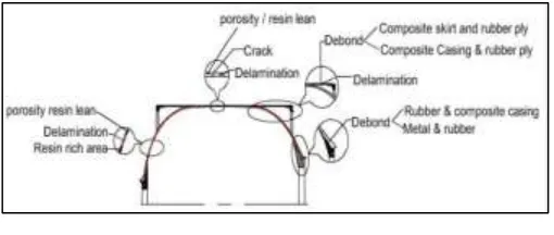
point contact (A-scan). While testing it, is highly essential to ensure probe to probe alignment so as to get exact signature.Fig – 7: Critical defect mode
Here low frequency, dry coupling and point to point contact (A-scan) has been followed. Ultrasonic flaw detector Sonatest MS410D and probe of 0.5 MHz shown in figure 8(a) has been selected. One reference block is made simulating defect such as delamination. Figure 8(b) shows reference block having dimensions of 90*90*10mm showing 50% healthy zone and 50% defective zone (delaminated zone). Above reference blocks is made up of carbon epoxy material system as equivalent to pressure vessel.
Fig - 8(a): Test set up Fig - 8(b): Reference block
Ultrasonic response on reference block having healthy and delaminated zone is studied. Figure 9(a) shows received ultrasonic signal through receiver from healthy zone which is more than 90% of the full scale height (FSH), however signal received from delaminated zone has been found to be less than 10% of the full scale height which is shown in figure 9(b). The significant attenuation of signal is attributed to the interfacial gap between layers.
[image:7.596.311.564.145.223.2](a) Healthy zone (b): Delaminated zone Fig - 9: Ultrasonic response on reference block
A composite pressure vessel having diameter in the order of 1000mm and length of 3000mm has been considered for this study. Whole pressure vessel is mapped in to grid points both in axial as well as circumferential direction by 24 and 8 zones respectively as shown in figure
10. Axial grid points are marked approximately 100mm distance apart. Testing was carried out manually by point to
Fig – 10: Grid mapping of full scale composite pressure vessel
[image:7.596.43.285.357.453.2]As per grid mapping mentioned in figure 10, testing has been carried out. At certain grid points, wherever signal loss was observed, additional dB has been pumped (in gain) to get more than 90% of the full scale height. Also fine grid mapping has been done adjacent to high dB signal loss points so as to map cumulative area showing degraded zone. Table 3 shows grading of zone based on additional dB points requirement. Grade A shows healthy and grade D depict a degraded zone. Considering this grading system, structural integrity assessment is carried out for each pressure vessel. Figure 11 shows complete pictorial view of ultrasonic response in terms of healthy zone and degraded zone on a final composite pressure vessel.
Table - 4: Ultrasonic test grade levels Sl.
No. Grade Testing dB 1. Grade A (90~100) % of T.L (the
best dB point) 2. Grade B Base dB+6 dB 3. Grade C Base dB+12 dB 4. Grade D Base dB+20dB
Fig – 11: dB loss/ultrasonic response for full scale composite pressure vessel
[image:7.596.309.559.426.625.2] [image:7.596.45.283.566.676.2]S2, S3 & S4) and four Linear Variable Differential Transducers (LVDT) (L1, L2, L3 & L4) are put in different stations of vessel.
(a) De-bond between main casing and skirt
(b) Delamination at dome
(c) Outer ply delamination
(d) Porosity
Fig – 12 (a-d): Represents few of the radiographic images of high dB loss zone
4.
ACCEPTANCE TESTING (PROOF
PRESSURE TEST)
Proof pressure test is performed to ascertain workmanship, material quality and structural integrity of the pressure vessel. It also ensures that hardware is acceptable for end use. This test also verifies leak proof- ness of all interface/seals, adequacy of joints and measurement of Strains/Dilations vis-à-vis prediction to evaluate margin of safety. Figure 13 represents proof pressure test set–up in which pressure vessel is pressurized up to proof pressure in hydraulic medium. Proof pressure is preferably 1.1 times higher than maximum expected operating pressure (MEOP). Figure 14 shows instrumentation layout for online measurement of strain and dilation during testing. Four Strain gauges (S1,
[image:8.596.69.259.91.567.2]Strains are measured at mid-cylinder, composite skirt, aft & fore end dome zones by strain gauges S1, S2, S3 and S4 respectively. Radial dilation at mid-cylinder is measured by L1 and axial dilation are measured by L2, L3 and L4 at aft end metallic flange, fore end and aft end metal fittings respectively. Above test procedure is followed for all six no. of pressure vessels.
[image:8.596.307.554.233.463.2]Fig – 13: Proof pressure test setup
[image:8.596.307.556.492.729.2]© 2019, IRJET | Impact Factor value: 7.211 | ISO 9001:2008 Certified Journal
| Page 964
5.0 RESULTS AND DISCUSSION
Six no of pressure vessels are realized implementing stated quality control methodology and quality assurance strategies as discussed in point 4. Identification for each pressure vessel is given as CR1 to CR6 respectively. Travel coupon properties, non-destructive testing and Proof pressure test results obtained for each pressure vessel are compared to check consistent in results and to validate quality control methodology. Each result is discussed in detailed in the following paragraphs.
5.1 Travel Coupon Test Results:
Density, resin content, glass transition temperature (Tg) and NOL ring hoop strength were measured in specimen derived from representative travel coupon of each pressure vessel. Average value of each pressure vessel is plotted and shown in fig 15, 16, 17, and 18 respectively. All the results are meeting the specification as mentioned in table 1. Also standard deviation and coefficient of variance for all the test results are showing encouraging results except NOL ring hoop strength where coefficient of variance is in the order of 6.5 %. Above variation is attributed to account of low resin content which leads to high fiber volume fraction and higher strength in CR02 sample.
5.2
Non
-Destructive Test Results: [image:9.596.313.558.92.234.2]Based on results of ultrasonic and X-ray radiographic test results, area of the degraded zone are mapped for each pressure vessel and comparison shown in figure 19. It has been found that, the total area of degraded zone (grade D) is less than 5% of the total scan area for all pressure vessels. Further, the area of degraded zones also shows decreasing trends as the pressure vessels manufactured over period of time.
[image:9.596.315.554.264.406.2]Fig – 15: Density plot for different pressure vessel
[image:9.596.312.555.431.753.2]Fig – 16: Resin content plot for different pressure vessel
Fig – 17: NOL strength plot for different pressure vessel
Fig – 18: Tg plot for different pressure vessel
[image:9.596.33.289.538.684.2]5.3 Proof Pressure Test Results:
Strain at mid cylinder and aft end domes has been considered for comparison. Similarly radial dilation at mid cylinder and axial dilation at aft end metal fitting are taken in to consideration and results of the same are given figure 20 (a), (b) & 21 (a), 21 (b) respectively.
Fig - 20 (a): Dilation at mid cylinder
Fig - 20 (b): Dilation at aft end metal fitting
Fig – 21 (a): Strain at mid-cylinder
Fig – 21 (b): Strain at aft end dome
All the experimental results of dilation vs. pressure & strain vs. pressure curves depicted are following same trend and linear in behaviour. Regression analysis for each results are showing encouraging results and R2 showing
more than 0.95. The good agreement with specification and the low dispersion behaviour demonstrate the consistent and repeatability of composite pressure vessel performance. Marginal non-linearity in strain and dilations observed on account of raw material batch to batch variation, certain uncontrollable process variable, offset in strain gauge orientation and variation in profile at measured station.
5. CONCLUSION
[image:10.596.304.559.64.279.2] [image:10.596.35.288.185.745.2]© 2019, IRJET | Impact Factor value: 7.211 | ISO 9001:2008 Certified Journal
| Page 966
ACKNOWLEDGEMENT
The authors wish to express their sincere acknowledgement of the support provided by Director, Advanced Systems Laboratory, Technology Director, CPDC and Shri Rama Rao in carrying out this work.
REFERENCES
1. F. Betti, P. Perugini, A. Mataloni, N. Tessitore, A. Leone, A. Di Cosmo, “Design and Development of VEGA Solid Rocket Motors Composite Cases,” 43rd AIAA/ASME/SAE/ASEE Joint Propulsion Conference & Exhibit, 8-11 July 2007, Cincinnati, OH, AIAA 2007-5810.
2. Michele Biagi, Alain Mauries, “Structural Qualification of P80 Solid Rocket Motor Composite Case,” 47th AIAA/ASME/SAE/ASEE Joint Propulsion Conference & Exhibit, 31 July - 03 August 2011, San Diego, California.
3. M. Madhavi, K. V. J. Rao and K. Narayana Rao, “Design and Analysis of Filament Wound Composite Pressure Vessel with Integrated-end
Domes,” Defence Science Journal, Vol. 59, No. 1, January 2009, pp. 73 -81 , 2009, DESIDOC.
4. D Cohen, “Influence of filament winding parameters on composite strength quality and strength,” Composite Part A: 28A (1997) 1035-1047, Elsevier Science limited, 1997. 5. Lokesh Srivastava ,V. Veena, S. K. Behera, J. K.
Mishra, S. Srinivasa Gopal, “Qualification of Upper Stage Composite Rocket Motor Casing,” Journal of Material Science and Mechanical Engineering (JMSME) Print ISSN: 2393-9095; Online ISSN: 2393-9109; Volume 2, pp.18-23, Number 10, April-June, 2015.
6. S. T. Peters, W. D. Humphrey & R. F. Foral, “Filament Winding Composite Structure Fabrication”, Second Edition, Society for the Advancement of Material and Process Engineering (SAMPE).
7. P. K. Mallick, “Fiber reinforced composites (materials,