warwick.ac.uk/lib-publications
Original citation:
Gale, Stuart and Lewis, Wanda J.. (2016) Patterning of tensile fabric structures with a
discrete element model using dynamic relaxation. Computers & Structures, 169 . pp.
112-121.
Permanent WRAP URL:
http://wrap.warwick.ac.uk/78675
Copyright and reuse:
The Warwick Research Archive Portal (WRAP) makes this work of researchers of the
University of Warwick available open access under the following conditions.
This article is made available under the Creative Commons Attribution 4.0 International
license (CC BY 4.0) and may be reused according to the conditions of the license. For more
details see: http://creativecommons.org/licenses/by/4.0/
A note on versions:
The version presented in WRAP is the published version, or, version of record, and may be
cited as it appears here.
Patterning of tensile fabric structures with a discrete element model
using dynamic relaxation
q
Stuart Gale
⇑, Wanda J. Lewis
School of Engineering, University of Warwick, Coventry CV4 7AL, United Kingdom
a r t i c l e i n f o
Article history:
Received 27 May 2015 Accepted 17 March 2016 Available online 4 April 2016
Keywords:
Patterning
Computational methods Woven fabrics Membrane structures Dynamic relaxation
a b s t r a c t
Tensile fabric membranes present opportunities for efficient structures, combining the cladding and support structure. Such structures must be doubly curved to resist external loads, but doubly curved surfaces cannot be formed from flat fabric without distorting. Computational methods of patterning are used to find the optimal composition of planar panels to generate the form, but are sensitive to the models and techniques used. This paper presents a detailed discussion of, and insights into, the computational process of patterning. A new patterning method is proposed, which uses a discrete model, advanced flattening methods, dynamic relaxation, and re-meshing to generate accurate cutting patterns. Comparisons are drawn with published methods of patterning to show the suitability of the method.
Ó2016 The Authors. Published by Elsevier Ltd. This is an open access article under the CC BY license (http:// creativecommons.org/licenses/by/4.0/).
1. Introduction
Tensile fabric structures are lightweight structural forms comprising a fabric membrane tensioned between a boundary of rigid structural elements and/or flexible cables. Such structures are characterised by their ability to resist external loading only through increased tension in the membrane surface, which is in turn resisted by compression and bending in supporting elements. To gain adequate stiffness, surface curvatures must be relatively high[1], and such doubly curved forms provide greatest stability under external loading. The surface shape of tensile fabric struc-tures cannot be defined geometrically by the designer, but must be generated throughform finding[2,3]– a computational process that finds the equilibrium position of a structure for a given stress state.
Prescribing a uniform pre-stress at the form finding stage results in a stable minimal surface – a surface with minimal area
[4,5]. Combining a uniform pre-stress and a boundary with an
appropriate number of alternately high and low points gives a min-imal surface with sufficiently high curvatures to resist external loading. Such a structure can be considered optimal owing to: (i) an absence of stress concentrations under permanent loading,
and (ii) a minimum of material used to achieve the form. Uniformly tensioned membranes are superior in their performance under external load, as they are less likely to wrinkle or fail by fatigue, as stated in the European Design Guide for Tensile Surface Structures[6].
Unfortunately, doubly curved surfaces are not developable – they cannot be flattened into a plane without distorting[2,7,8]. Structural fabrics are manufactured as flat panels, and conse-quently tensile fabric structures cannot be formed without incur-ring stresses in the surface. Structural fabrics are manufactured with a typical width of 2–3 m[9], and a maximum width of 5 m
[10], requiring multiple panels for larger structures. The shape of these panels affects the final form and stress distribution of the membrane.
The combination of double curvature and manufacturing straints necessitates a specialist design process, patterning, be con-ducted. Patterning seeks to determine the arrangement of planar fabric panels such that, when the panels are assembled, the desired 3D form is achieved, and the stress distribution is as close as pos-sible to that intended during form finding. Fabric usage should also be minimised.
This paper presents a review of existing patterning methods, and proposes a new methodology for patterning. Insights into the computational process of patterning are presented, challenges are highlighted, and solutions are proposed through discussion of the new method. Comparisons with two published methods are included to demonstrate the suitability of the proposed method for tensile fabric structures patterning.
http://dx.doi.org/10.1016/j.compstruc.2016.03.005
0045-7949/Ó2016 The Authors. Published by Elsevier Ltd.
This is an open access article under the CC BY license (http://creativecommons.org/licenses/by/4.0/).
qResearch funded by The Engineering and Physical Sciences Research Council
(EPSRC), United Kingdom.
⇑Corresponding author.
E-mail address:[email protected](S. Gale).
Contents lists available atScienceDirect
Computers and Structures
2. Computational patterning
Historically patterning was conducted using physical models. Computational methods of patterning are now used, and the gen-eral process of patterning is divided into four steps:
1. Subdivisionof the membrane into panels by seams
2. Flatteningof each 3D membrane panel into 2D
3. Stress reductionto reduce stresses from flattening
4. Compensationto give panels which are mostly stress-free and
suitable for cutting
An additional fifth step can be included:
5. Assembly of panelsto realise the final 3D form and stresses.
Step 1 – Seam definition, concerns the division of the form-found membrane surface into panels (Fig. 1). The divisions are defined by seams which generally take the form of sewn and/ or welded overlapping panels of fabric[11].
It is considered good practice to establish seam lines along geo-desics [7,9,12]. Geodesics are lines of minimum distance over a surface[7,13], and are the path adopted by a constant stress cable stretched over the surface. Consequently, geodesic seams do not introduce undesirable stresses into the membrane. Seams physi-cally dictate the panel size, and affect the subsequent flattening, stress reduction and compensation of the individual panels. For practical reasons, seams should, run through the regions of low curvature to avoid possible wrinkling during sewing and welding. At the same time, they should be spaced reasonably, to ensure the curvatures across the panels remain low.
Step 2 – Flattening, concerns the development of a portion of the 3D form-found membrane surface into the 2D plane. Flat-tening is discussed further in Section3.1.
Step 3 – Stress reduction,concerns the application of iterative
methods to the flattened panel geometry to reduce stresses. Stress reduction is discussed further in Section3.2.
Step 4 – Compensation, concerns the shrinking of the pattern to account for tensioning of the membrane during construction. Steps 3 & 4 can be performed in one process[8], and the rela-tionship between the two is discussed in Section3.3.
Step 5 – Pattern assembly, can be included in patterning schemes to calculate the final geometry and stresses in the con-structed membrane. The cutting pattern is assembled according
to the physical boundary conditions, and relaxed into its equi-librium shape, giving the final geometry and stresses.
3. Approaches to computational patterning
Whilst the general computational process of patterning follows the above structure, there are differences in its implementation, particularly at the stress reduction and compensation stages.
3.1. Flattening
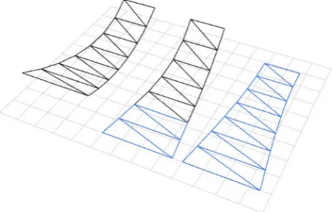
As stated earlier, the panels defined on the form found membrane surface must be flattened into the plane, and this incurs distortions. Historically, flattening was undertaken using so called ‘‘cloth
unfold-ing” [14](Fig. 2) – membranes were reduced to a series of
devel-opable polyhedral strips that were unfolded [14–16]. These strips were then compensated in consideration of the pre-stress[9], and did not include stress reduction methods. Such strips required a compromise on accuracy[16], as high curvatures across a strip ren-dered polyhedral approximations to the surface inadequate[14].
Because of the poor patterns that trivial unfolding processes (in the absence of stress reduction procedures) produce, recent methods use more complex computational techniques to minimise flattening distortions [16], as discussed further in the following section. With the introduction of methods of stress reduction, flattening is now most commonly used to generate an initial geometry prior to using these procedures. Different flattening methods are highlighted in Section5.1.
3.2. Reduction of flattening stresses
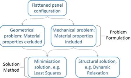
The problem of minimising flattening stresses can be formu-lated in two ways; as (i) a geometrical problem, independent of mechanical properties [17], and as (ii) a mechanical problem in which material properties are included (Fig. 3).
Solutions to both problem formulations may be further cate-gorised. The first of the two main solutions, may be termed the
‘minimisation solution’, and is more common. Here, flattening is for-mulated as an optimisation problem, where the intention is to minimise (i) in the case of a geometrical problem formulation, dis-tortionsinduced by flattening[17], and (ii) in the case of a mechan-ical problem formulation, thestressesinduced by flattening, or the deviation of the actual stress from the design stress[2,14]. This is achieved by seeking to minimise an objective function represent-ing the strain or stress deviations. Minimisation solutions to geo-metrical [18] and mechanical [2,14] problems have been achieved, using, for example, methods such as least squares.
[image:3.595.53.285.67.234.2]The second solution may be termed the ‘structural solution’, as the un-equilibrated pattern is relaxed into an equilibrium state Fig. 1.Seams and extracted panel for a catenoid surface.
[image:3.595.320.555.588.737.2]under the action of the out-of-balance forces resulting from the flattening strains[9].
Fig. 3summarises the problem formulations, solutions, and the
relationship between them. Both solutions commonly make use of iterative procedures. Consequently, all solution methods require an initial starting configuration, which is provided by the flattening process (Fig. 3). The quality of the flattened panel configuration generated by methods such as those outlined in Section5.1, affects the efficacy of both structural and minimisation solutions. This is explored further in Sections3.4 and 5.2.1.
3.3. Compensation
Because the 3D membrane geometry represents strained fabric, and the fabric pattern must be cut from unstrained cloth, the cut-ting pattern must have smaller characteristic dimensions (e.g. panel width and length) than in the assembled membrane. Com-pensation is applied to shrink the flattened panel and give a pat-tern suitable for cutting from planar cloth. Compensation can be applied using the same minimisation [2] or structural solution methods [9] used to reduce flattening distortions, or by scaling the characteristic dimensions of a panel, according to the elastic properties of the fabric. If minimisation or structural solution methods are used, they are typically integrated with reduction of the flattening stresses.
It is possible to perform stress reduction and compensation on a flattened panel as one process[8]. In this regard, there is division among researchers, with some conducting the two processes sep-arately[18], and others preferring to conduct them simultaneously
[8,9]. To achieve integrated stress reduction and compensation,
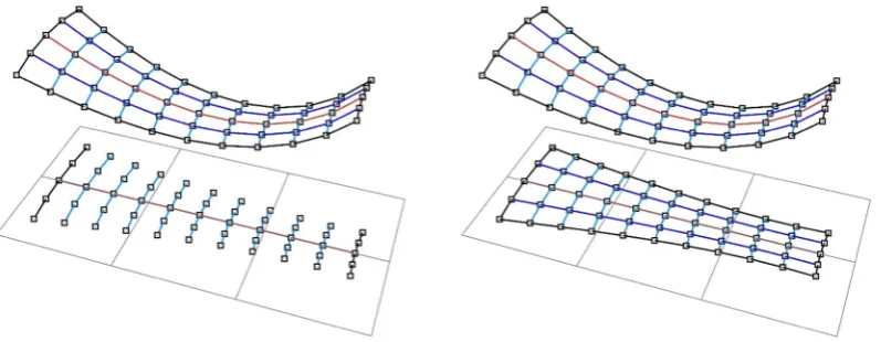
pre-stress terms must be included in the problem formulation. Thus integrated reduction and compensation is achievable when using the mechanical problem formulation only. Conducting the processes separately results in a geometrical problem, independent of the mechanical behaviour[17]. Mechanical properties must then be introduced for compensation. The difference between distinct
stress reduction and compensation, andintegratedstress reduction and compensation is highlighted inFig. 4.
3.4. The influence of the flattened panel configuration on stress reduction and compensation
Whether the stresses due to flattening are reduced simultane-ously with those owing to pre-stress or not, the procedures used to find the equilibrium stress-state are iterative. The accuracy and stability of iterative schemes are dependent on the initial con-ditions and the chosen method of solution, as mentioned in[2,8]
with respect to the Newton–Raphson procedure. Such issues with convergence of the Newton–Raphson iteration are representative
of a more general issue affecting iterative stress reduction meth-ods: the need for a suitable starting configuration. While efforts have been made to circumvent or mitigate issues of convergence
[2] associated with poor starting geometry, computational effi-ciency is enhanced when the starting geometry is close to the solu-tion geometry, as reported in reference to form finding in[8]. Thus, a method of defining the starting (flattened) geometry, which min-imises distortions that must be reduced by stress reduction meth-ods is desirable.
To the authors’ knowledge, no investigation into the effects of different flattening methods, or comparison of different methods has been conducted.Here the emphasis is on the process by which one generates the starting (flattened) geometry for an iterative stress-reduction or structural relaxation scheme.Some examples of flattening methods include: simple direct projection to the plane
[8,15]; projection of surface points to the tangent plane of the
sur-face at each point[18]; and projection to a defined intermediate developable surface that is subsequently unrolled to give a planar un-equilibrated pattern[9]. It is possible, with discrete element models (discussed in Section3.6), to employ unfolding methods for flattening relatively easily.
3.5. Pattern assembly and equilibrium finding
Pattern assembly can be included in the patterning process to evaluate the suitability of the patterns generated by previous steps
[15]. The cutting pattern is assembled, and translated into the boundary configuration. It is then analysed to find the equilibrium state. During the stress reduction process, it is usually not possible to nullify the stresses due to flattening. Therefore the reverse of the residual stresses from flattening and stress reduction would be expected to appear along with the pre-stress in the assembled equilibrated structure. The suitability of the cutting pattern can be evaluated by comparing these stresses with the prescribed pre-stress, and by measuring the deviation of the geometry from the form-found geometry.
3.6. Fabric modelling
Architectural fabrics are heterogeneous, comprising woven fibres with a polymer topcoat. Their tensile stiffness and load car-rying capacity is derived principally from the fibres[19]. The coat-ing makes a negligible contribution to the tensile stiffness, but is the main contributor to the shear stiffness. The fibres are bidirec-tional, and are generally orthogonal in the planar cutting pattern, but to adopt a doubly curved geometry the weave must shear
[12,20]. At the design stage, fibre directions are known only in
the planar fabric that forms the cutting pattern – fibre directions in the assembled membrane are unknown.
In addition, structural fabrics are anisotropic, and material properties must be known in the two fibre directions; the (stiffer)
[image:4.595.46.272.68.203.2] [image:4.595.309.546.68.163.2]warp, andweft; such material data is not readily available. Strains in the computational model must be related to stresses using Fig. 3.Relationship between stress reduction problem formulations and solutions.
appropriate stiffness values, and the relation is complicated by the changing fibre directions. Computational modelling must account for this changing material basis, and accommodate the relative changes of the warp and weft directions.
There remains discussion concerning the most appropriate model for modelling of tensile structures[16]. Here, the specific implications of different models for patterning are discussed.
Fabric models can be divided into two broad categories; those employing continuum assumptions[2,8,9,15], and those treating the fabric as a structural mechanism comprising discrete compo-nents[21]. Continuum models, solved using finite element meth-ods, provide efficient models for analysis [21], but assume homogeneity of the surface. This assumption precludes continuum models from accounting for stiffness variations in sheared geome-tries, such as those present when assembling the structure from planar panels.
Discrete models have received most attention in modelling fab-rics for non-structural textiles and computer graphics[22–24], but offer an attractive proposition for the modelling of structural tex-tiles, because they reflect the heterogeneous micro-structure beha-viour of the fabric. The changing behabeha-viour of the fabric when undergoing shear deformation can be more accurately modelled using discrete models. However, discrete models suffer from inef-ficiency as the fabric behaviour becomes more complex, which is captured in ‘‘composite crimp” [16] models. The discrete ‘‘particle-spring” model proposed in [23] utilised extension springs, shear springs, bending springs and twisting springs. Such a model is unnecessarily complex for tensile structures patterning owing to the negligible bending and twisting stiffness of architec-tural fabrics. However, a model derived from similar tensile and shear elements would provide a good basis for fabric patterning. The discrete element method proposed in[21]used fibre tensile elements, fibre shear elements, fibre crimp elements, coating ten-sile elements, and coating shear elements. Similarly, such a model, for patterning, would benefit from simplification, for example by retaining only fibre tensile elements and coating shear elements.
A further alternative is that presented in[25], in which angular deformations between tensile elements were related to forces at a node. In this paper, in Sections4 and 5, we present a new discrete model which preserves some elements of the approach used in
[25]and incorporates tensile and shear elements.
3.6.1. Challenges in computational modelling
As mentioned in Section3.4, the flattened panel configuration affects the results of the subsequent stress reduction and compen-sation processes. The research is motivated by the need to have easily defined projections that reduce distortions in the flattened panel configuration, before stress reduction schemes are applied.
The direction of the fibres, as defined by the design engineer when orienting the fabric with respect to the overall structure, has been shown to affect the structural behaviour of the membrane under external load[26]. Differing fibre directions along the seam line of adjacent panels[20]also affect the behaviour of the mem-brane. However, the effect of the disparity between assumed fibre directions during computational modelling and actual fibre direc-tions in the erected membrane structure has not yet been quantified.
4. Proposed fabric mechanical model
With a form found shape generated from continuum elements using RhinoMembrane[27], a spline surface interpolated through the mesh nodes facilitates the construction of geodesics for panel seams and mesh line definition. For modelling the fabric and com-puting stresses with respect to warp and weft directions during
flattening, stress reduction and compensation, a moment-less dis-crete element model, solved bythe dynamic relaxation method[7], is proposed. This has the advantage of offering a straightforward modelling method, in which elements representing the fabric are assigned axial stiffness properties representing either warp or weft fibre directions, and retain this stiffness throughout the modelling. Changes in the orientation of the fibres are directly reflected in the stress computation.
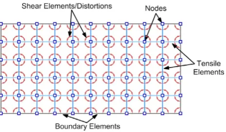
As architectural fabrics are considered to have negligible bend-ing stiffness[1], it is similarly assumed that their twisting stiffness is negligible. The shear stiffness of architectural fabrics is low[16], and in the proposed model is taken as 1/20 of the tensile stiffness
[12,26].Fig. 5shows the configuration of our proposed discrete
ele-ment model in which tension and shear actions are decoupled. A further description of the shear model is given in the follow-ing section.
4.1. Shear modelling
The shear resistance of the fabric is formulated in the proposed discrete model by examining the rotation between warp and weft elements at a node, and considering the shear forces required to produce this shear deformation. In this way the proposed method is similar to that described in[25], but overcomes several limita-tions. The original method required four elements to calculate shearing, a regular spacing of tensile elements, and for the ele-ments to remain in-plane. Similarly, the unstrained geometry of the fabric was used to derive the directions of the resulting forces, limiting the formulation to small deformations.
The proposed method models the shear response of the fabric using two neighbouring elements only. Forces derived from the rotation between elements are apportioned to the common node only. The direction of the resultant force is derived from the deformed configuration of the elements, accommodating larger deformations.
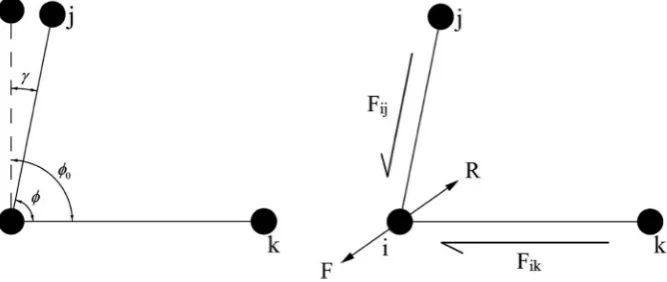
Fig. 6shows the rotation between two elements at a node due
to shearing. The shear strain
c
is calculated from the change in angle between the elements, from an initial rest angle /0. This shear strain is related to a shear stresss
through the shear modu-lusG. The shear forces,FijandFik, required to produce such a shearstress, act along the directions of the tensile elements, and are resolved into forceFat the common node between the two tensile elements. ForceFis the force required to produce the shear defor-mation, and thus represents an external force. The resistance of the fabric to this deformation is thus the vector opposite ofF, defined asR. Thus forceRis apportioned to the node.
[image:5.595.322.555.604.740.2]In the computational discrete element model, this process is achieved using shear elements between warp and weft elements, as indicated inFig. 5.
5. Proposed patterning method
5.1. Flattening methodology
As discussed previously, the fibre directions (and consequently principal stiffness directions) are not known in the 3D configura-tion before patterning. When meshing a panel prior to flattening and stress reduction, the choice of mesh impacts on the calculated strain, and consequently the suitability of the patterns generated. A robust material relationship that accommodates the varying aniso-tropy of the fabric is required, and this is achieved using a discrete element model. However, there is still a choice to be made as to the initial directions of the elements.
It would appear that, for maximum accuracy of flattening, a geodesic mesh should be used on the 3D form, as it would repre-sent minimum distances over the curved surface. However, initial investigations by the authors into the use of meshes with geodesic generator curves highlighted a problem of numerical ill-conditioning, due to an uneven spacing of elements negatively affecting the surface stiffness. Constructing the mesh from geode-sic curves along the direction of higher curvature, and interpolated curves in the second direction, was found to produce a superior mesh for further analyses.
5.1.1. Proposed un-roller method – advantages over direct projection flattening
As mentioned in Section3.4, the extent of deformation resulting from flattening affects the subsequent stress reduction and com-pensation analyses. Flattening methods that give planar panel con-figurations with reduced stresses are therefore desirable. As part of the patterning method presented in this paper, we propose an un-roller method for flattening. This method generates initial planar panel configurations, which improve the subsequent stress reduc-tion and compensareduc-tion processes. In this and the following sec-tions, the un-roller method is compared with a trivial projection method, to highlight the advantages of the method.
The un-roller method takes a row of elements along the centre-line of the panel, and unrolls this centrecentre-line to the plane. Rows of elements in the other direction are unrolled in the plane using the planar centreline. Elements in the direction of the original cen-treline are then interpolated using the planar nodes.Fig. 7 illus-trates this method. The flattened panel configuration generated using this method, for a panel on the catenoid shown inFig. 1, is shown inFig. 8.
An alternative, direct projection method is a more extreme and simpler method that has been used by some researchers[8], and confirmed by others [15], in which nodes are projected directly to the plane. In effect, the global coordinates of each nodeðx;y;zÞ
are set to ðx;y;0Þ. The flattened panel configuration generated using this method, for the same panel as inFigs. 1 and 8, is shown inFig. 9.
The strains in the model are calculated using the 3D doubly curved shape as the un-deformed element reference lengths. The tensile stiffness of the fabric is modelled as 500 kN/m in both warp and weft directions, giving rise to the stresses shown inFigs. 8
and 9.
It is immediately clear that the stresses in the configuration generated by the direct projection method are much higher than those in the configuration generated using the un-roller function, and are out of the working range of stresses of the fabric. Section5.2.1highlights the issues these high stresses incur when trying to remove the flattening stresses.
It is possible to use a developable surface instead of a direct plane projection, and then unroll the surface to obtain a flattened configuration, as proposed in [9]. This, however, adds to the computational effort and does not avoid errors associated with the projection onto a developable surface.
5.2. Proposed compensation – integrated stress reduction and compensation
Here, integrated compensation to remove the pre-stress and reduce flattening stresses is employed. Referring to the termino-logy in Section 3, the mechanical problem formulation is solved using astructural integrated compensationmethod. Dynamic relax-ation[7]is the chosen analysis method for finding the equilibrium geometry of the panel. Under imposed flattening stresses during compensation, element forces at nodes are summed and resultant nodal forces are found. Dynamic relaxation with kinetic damping is then used to find the equilibrium geometry, with motion being first initiated from the initial resultant nodal forces. Specific nodes in the panel must be restrained to prevent rigid body translations and rotations.
5.2.1. The effect of flattened panel configuration on integrated stress reduction and compensation
The panel has a large number of degrees of freedom compared with the restraints. Consequently, the quality of the flattened panel configuration, on which dynamic relaxation is conducted, affects the performance of the analysis. If dynamic relaxation is conducted on the flattened panel geometry shown inFig. 8, the analysis con-verges, and the residual stresses in the panel are negligible, as shown inFig. 10. It is not possible to entirely nullify the stresses, owing to the non-developability of the form found shape.
[image:6.595.127.461.70.211.2]in the flattened panel configuration generated with direct projection cause numerical ill-conditioning. Large stresses in the elements lead to high residual forces at the nodes, and dispropor-tionately large displacements compared to the nodes with lower residual forces. In the worst cases this leads to divergence, as in Fig. 11, but in cases where convergence is achieved, the
equilibrium panel geometry suffers from large local distortions and is unsuitable for a final cutting pattern.
5.3. Panel assembly and re-meshing
To evaluate the suitability of patterns generated using integrated stress reduction and compensation, the proposed patterning method includes assembly of the planar pattern. To increase the accuracy of the fabric model, the planar panels are re-meshed, before assembly, with an orthogonal mesh to give a realistic representation of the warp and weft directions.
5.3.1. Orthogonal re-meshing
As discussed in Section3.6, the fabric weave is orthogonal in plane, but must shear to adopt a doubly curved geometry
[12,20]. Prior to flattening, assumptions must be made concerning
the fibre directions. However, after flattening and compensation, it is possible to re-mesh the cutting pattern with an orthogonal mesh.
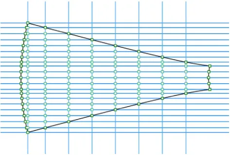
Our proposed method uses orthogonal re-meshing to give a more accurate representation of the fabric. The planar boundary of the compensated panel is intersected with a series of orthogonal gridlines to generate a mesh, as shown inFig. 12. Similar to the mesh prior to flattening, mesh conditioning is an important feature. It is generally beneficial to ensure the mesh is triangulated along the boundaries; if the mesh is not triangulated, issues with convergence can occur, as explained below.
[image:7.595.104.503.66.221.2]A close up of a non-triangulated mesh is shown inFig. 12. It can be seen that there are elements with comparatively short lengths along, and neighbouring, the boundary. These elements cause similar problems to those outlined in Section5.2.1; their compar-atively short lengths lead to large variations of stress between Fig. 7.Unrolling of the mesh to the plane.
[image:7.595.50.288.548.641.2]Fig. 8.Stresses when flattened using a simple un-roller method.
Fig. 9.Stresses when flattened using direct projection.
Fig. 10.Successful convergence when relaxing a panel of good initial geometry (shown inFig. 8).
adjacent elements. Additionally, where elements along the bound-ary form a polygon with greater than four vertices/edges, as shown
inFig. 12where the elements form a pentagon ABCDE, numerical
ill-conditioning will occur due to unrestricted movement. This effect is particularly pronounced where the boundary elements represent constant force cables; in this case, the boundary element between nodes C & D will reduce in size until the nodes are virtually coincident.
To ensure triangulation along the boundaries, the orthogonal gridlines used to generate the mesh should be defined using the panel boundary. Defining nodes along the boundary of the panel, and constructing lines along two orthogonal vectors for the relevant nodes, results in a triangulated mesh, shown inFig. 13. Careful definition of the boundary nodes is required to ensure the resulting elements are appropriately spaced.
In addition to ill conditioning, re-meshing can result in a loss of accuracy. The boundary of the compensated panel is represented by a polyline. Intersecting a grid with this polyline, and regenerat-ing the boundary elements, can result in a deviation of the boundary geometry from the original, if the mesh is not sufficiently fine. This can be avoided by constructing the orthogonal grid with the boundary nodes of the compensated panel as the starting points for defining the orthogonal lines.
5.3.2. Dynamic relaxation of panel assembly
With a suitable orthogonal mesh defined on each of the planar panels, the pattern can be mapped into the physical 3D boundary, and adjacent panels joined. At this stage, the assembly is not in equilibrium. Dynamic relaxation is again used to find the
equilibrium geometry and estimate the final stresses in the mem-brane. There are sufficient restraints at this stage of the process for the dynamic relaxation analysis to converge, even in the presence of large local distortions caused by the mapping. Consequently, the mapping of the 2D panels to the 3D boundary geometry does not have to be sophisticated, unlike the flattening of the 3D panels for stress reduction and compensation.
6. Comparative studies
The efficacy of the proposed patterning method is now illus-trated by comparison with two published results. The results are first shown without modelling the shear resistance when re-assembling the cutting patterns (Sections 6.1 and 6.2). The effect of the shear stiffness of the fabric is then presented by a fur-ther analysis (Section6.3).
6.1. Comparison with Moncrieff & Topping[15]
The methods used in [15] employed a continuum model for patterning, except for the final step in which the surface was converted to tension links. Three procedures for patterning were employed: cloth unfolding, dynamic relaxation and least squares minimisation. Here, we compare with the third example from
[15], where the flattening method used geodesic lines to extract panels from the 3D surface followed by least squares minimisation to reduce distortions due to flattening. The panels were assembled using an orthogonally meshed cutting pattern, and analysed to find the final stresses and geometry.
A catenoid with dimensions taken from[15], with ring diame-ters of 3.2 m and 12 m respectively, a ring separation of 2.0 m, and an isotropic pre-stress of 3 kN/m, was form found and patterned for comparison. Owing to symmetry,¼ of the surface was modelled. The surface was patterned using the methods pro-posed in Sections4 and 5, and using 6 panels for the¼surface; 24 panels having been used for the whole surface in[15]. Following flattening, stress reduction and compensation, the panels were re-meshed in plane, with an orthogonal mesh, for assembly and tensioning into the boundaries. Dynamic relaxation was then used to find the equilibrium shape for the assembled, in boundary, geometry. Since no shear stiffness was given in[15], the analyses were conducted with a shear stiffness of zero throughout.
[image:8.595.95.490.67.210.2]The equilibrium geometry and final stress deviations for the warp and weft directions are shown inFig. 14. The greatest stress deviation where stresses are higher than the intended pre-stress is +0.43 kN/m, and occurs in the warp elements near the seams, towards the upper fixed ring boundary. The greatest stress devia-tion where stresses are lower than the intended pre-stress is Fig. 12.Generation of mesh by intersection with grid and resulting ill conditioning.
[image:8.595.40.277.571.731.2]0.846 kN/m, and occurs in the weft elements near the seams, towards the upper boundary. The maximum and minimum stresses represent deviations from the assumed pre-stress of +14.3% and28.2% respectively, in comparison with[15], where the maximum and minimum stress deviations could only be estimated from the graph, giving values of 20% and18% respec-tively. Although the ranges of stress deviations are similar, the areas affected in the case of[15] were in the main body of the surface (not near the boundaries). The differences in the mapping and in surface representations contributed to differences in the results.
6.2. Comparison with Linhard et al.[8]
The methods used in [8] employed a continuum model, and used a mechanical problem formulation with a stress minimisation solution to simultaneously reduce stresses and achieve compen-sated patterns.
A catenoid with dimensions taken from[8], with ring diameters of 1.2 m and 5.6 m respectively, a ring separation of 1.0 m, and an isotropic pre-stress of 2 kN/m, was form found and patterned for comparison. Owing to symmetry, again ¼ of the surface was modelled. The surface was patterned using the methods proposed in Sections4 and 5, and using 3 panels for the¼surface; 12 panels having been used for the whole surface in[8]. Following flattening, stress reduction and compensation, the panels were re-meshed in plane, with an orthogonal mesh, for assembly and tensioning into the boundary. Dynamic relaxation was then used to find the equilibrium shape for the assembled, in boundary, geometry. The shear stiffness of the fabric was not included.
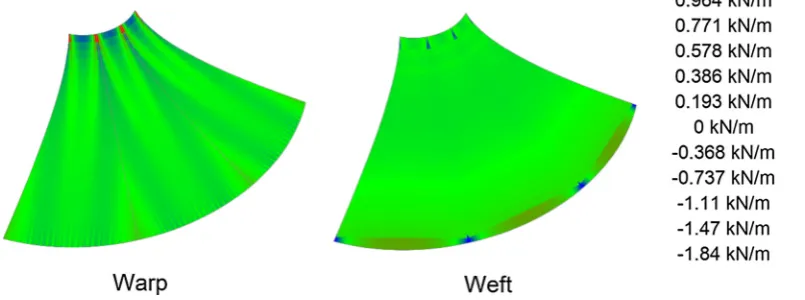
Fig. 15 shows the final geometry and resulting deviations of
the stresses from the intended pre-stress of 2 kN/m in the warp and weft directions. The greatest stress deviation where stresses are higher than the intended pre-stress is +0.964 kN/m, and occurs in the weft elements where the seams meet the lower fixed ring boundary. High stresses also concentrate in the weft elements where the seams meet the upper boundary, in the warp elements neighbouring the seams, and in the warp elements towards the upper boundary.
The greatest stress deviation where stresses are lower than the intended pre-stress is 1.84 kN/m, and occurs in the warp elements adjacent to the seams, where the seams meet the upper boundary. These stresses occur over a very small area, and indicate an excess of fabric in the cutting pattern in this area. Lower stresses also occur in the weft elements in the centres of the panels, towards the lower boundary.
The maximum and minimum stresses represent deviations of +48.2% and92.0% respectively from the prescribed pre-stress. In
[8] principal stresses are given, corresponding to the maximum and minimum deviations of +2.08 kN/m (+104%) and0.83 kN/m (41.5%) respectively, with higher stresses than the intended pre-stress seen near the seams towards the upper boundary, and lower stresses are seen in the centre of the panel towards the upper ring boundary. The stress distribution inFig. 15bears some similarities to that of[8], with higher stresses concentrating near the seams, towards the upper boundary, corresponding to the areas of higher curvature.
6.3. Comparison with Linhard et al.[8]including shear
The same geometry from Linhard et al. [8] was analysed again, using the methodology discussed in Sections 4 and 5, but this time including the shear resistance of the fabric. No explicit value for shear stiffness was given in[8], so the shear stiffness was taken as 1/20 of the tensile stiffness, as recommended
in [12,26]. For the tensile stiffness of E= 220 kN/m, this rule of
thumb gives the shear stiffness,G= 11 kN/m. This value of shear stiffness was included when generating the cutting pattern through flattening, stress reduction and compensation, and again when re-assembling and relaxing the orthogonally meshed panels.
Fig. 16 shows the final geometry and resulting deviations
of the stresses from the intended pre-stress of 2 kN/m in the warp and weft directions. The greatest stress deviation where stresses are higher than the intended pre-stress is +2.06 kN/m, and occurs in the warp elements near the seams, towards, but not immediately adjacent to, the upper boundary. High stresses concentrate along the seams in the warp direction, towards the upper boundary. Stresses above the intended pre-stress also occur in the weft elements near the seams, where the seams meet the upper and lower boundaries.
The greatest stress deviation where stresses are lower than the intended pre-stress is 0.395 kN/m, and occurs in the warp elements in the centre of the panel. Some stresses below the intended pre-stress also occur in the weft elements near the panel centres, adjacent to the boundaries. The stress distribution pre-sented inFig. 16is very similar to that of[8], with higher stresses concentrating near the seams, towards the upper boundary. The stresses reduce in magnitude away from the upper ring. A patch of low stress within the centre of the panel, towards the upper ring boundary is seen in bothFig. 16and[8].
6.4. Final comparison of results
Table 1shows the greatest stress deviations for all analyses. The
[image:9.595.87.513.74.222.2]with Linhard et al.[8], particularly when shear is included. It is evident that the inclusion of the shear stiffness is important, for both generating a suitable cutting pattern, and for analysing the assembly of this pattern. It has been suggested previously that since the shear stiffness of fabrics is low, it can be ignored[16]. However, results presented inFigs. 15 and 16indicate that this is not a safe assump-tion, even for relatively low values of shear stiffness.
7. Conclusions
This paper presents a review of patterning methodologies and highlights challenges in computational modelling of the problem. It is against this background that a new patterning approach, based on a discrete element model is proposed. This approach gives good
representation of the fabric membrane behaviour, allows for easy re-meshing prior to panel assembly, and is particularly suited to the method of dynamic relaxation employed at the integrated stress reduction and compensation stage.
Examples of patterning applied to a catenoid surface highlight the importance of investigating different methods of flattening and their effect on the stress distribution in the compensated (cutting pattern) panel. It is shown that poor flattening can not only adversely affect the solution, but can lead to a lack of convergence of the numerical solution.
[image:10.595.77.480.74.224.2] [image:10.595.67.509.263.408.2]The proposed discrete element model in conjunction with orthogonal re-meshing of the cutting patterns gives a realistic description of the fabric surface, most effectively at the pattern assembly step. Geodesic curves in the direction of highest curvature and interpolated curves in the second direction, prior Fig. 15.Deviation from intended pre-stress of 2 kN/m after pattern assembly and relaxation for Linhard et al.[8].
Fig. 16.Deviation from intended pre-stress of 2 kN/m after pattern assembly and relaxation for Linhard et al.[8], including shear resistance in the discrete model.
Table 1
Table of final stress deviations for all analyses.
Analysis Prescribed Positive stress Negative stress Pre-stress Deviation Deviation
(kN/m) (kN/m) (%) (kN/m) (%)
Geometry from Moncrieff & Topping[15]
Moncrieff & Topping[15] 3.00 Not given 20% Not given 18% Gale & Lewis (without shear) 3.00 +0.430 14.3% 0.846 28.2%
Geometry from Linhard et al.[8]
Linhard et al.[8] 2.00 +2.08 +104% 0.83 41.5%
[image:10.595.39.549.471.576.2]to flattening, give evenly spaced meshes that converge to suitable solutions, when reducing stresses and compensating the panel using dynamic relaxation. Meshes based on geodesics in two direc-tions were found to give rise to ill-conditioning of the numerical solution.
The inclusion of the shear stiffness throughout the analysis (cutting pattern generation and pattern assembly) has been shown to affect the final distribution of stresses in the assembled 3D shape. The results show the residual stresses after assembly to be within the ranges reported in literature where continuum, or hybrid: continuum/discrete models have been used. Our proposed discrete model is a simple alternative, shown to be suitable for cut-ting pattern generation. However, further work is needed to come up with guidance on suitable mesh configurations for various sur-face geometries.
References
[1]Gosling PD, Bridgens BN, Zhang L. Adoption of a reliability approach for membrane structure analysis. Struct Saf 2013;40:39–50.
[2]Bletzinger K-U, Linhard J, Wüchner R. Advanced numerical methods for the form finding and patterning of membrane structures. In: De Mattos Pimenta P, Wriggers P, editors. New trends thin struct formul optim coupled probl, vol. 519. WienNewYork: Springer; 2010. p. 133–54.
[3]Lewis W. Understanding novel structures through form-finding. Proc ICE – Civ Eng 2005;158:178–85.
[4]Bletzinger K-U, Wüchner R, Daoud F, Camprubí N. Computational methods for form finding and optimization of shells and membranes. Comput Methods Appl Mech Eng 2005;194:3438–52.
[5]Hildebrandt S, Tromba A. Mathematics and optimal form. Scientific American Library; 1985.
[6]Forster B, Mollaert M. European design guide for tensile surface structures. TensiNet; 2004.
[7]Lewis WJ. Tension structures: form and behaviour. Thomas Telford Publishing; 2003.
[8]Linhard J, Wüchner R, Bletzinger K-U. Introducing cutting patterns in form finding and structural analysis. In: Oñate E, Kröplin B, editors. Text compos inflatable struct II, vol. 8. Springer; 2008. p. 69–84.
[9]Brew JS, Lewis WJ. Spline-based and stress-monitored patterning of fabric structures. Comput Struct 2013;119:203–14.
[10] Seidel M. Tensile surface structures: a practical guide to cable and membrane construction. Ernst & Sohn, Verlag für Architektur und technische Wissenschaften GmbH & Co. KG; 2009.
[11]Houtman R, Werkman H. Detailing and connections. In: Mollaert M, Forster B, editors. Eur des guid tensile surf struct. TensiNet; 2004. p. 147–76. [12]Barnes M, Gründig L, Moncrieff E. Form-finding, load analysis and patterning.
In: Mollaert M, Forster B, editors. Eur des guid tensile surf struct. TensiNet; 2004. p. 205–18.
[13]Lewis WJ. Modeling of fabric structures and associated design issues. J Archit Eng 2013;19:81–8.
[14]Kim J-Y, Lee J-B. A new technique for optimum cutting pattern generation of membrane structures. Eng Struct 2002;24:745–56.
[15]Moncrieff E, Topping BHV. Computer methods for the generation of membrane cutting patterns. Comput Struct 1990;37:441–50.
[16]Moncrieff E. Systems for lightweight structure design: the state-of-the-art and current developments. In: Oñate E, Kroplin B, editors. Text compos inflatable struct, vol. 3. p. 17–28.
[17]Ströbel D, Gründig L, Singer P. Selected examples for the optimization of cutting patterns for textile membranes. In: Bletzinger K-U, Kröplin B, Oñate E, editors. VI int conf text compos inflatable struct struct membr 2013. Munich: International Center for Numerical Methods in Engineering; 2013. p. 258–67.
[18] Gründig L, Moncrieff E, Singer P, Ströbel D. High-performance cutting pattern generation of architectural textile structures. In: Papadrakakis E, editor. IASS-IACM 2000 fourth int colloquium comput shell spat struct, Chania-Crete; 2000. [19]Lewis W. Architectural fabrics. In: Forde M, editor. ICE man constr
mater. London: Thomas Telford Limited; 2009. p. 873–85.
[20] Wagner R. Basics in tension structures. Int J Sp Struct 2009;24:223–31. [21]Ballhause D, König M, Kröplin B. Modelling fabric-reinforced membranes with
the discrete element method. In: Oñate E, Kröplin B, editors. Text compos inflatable struct II. Springer; 2008. p. 51–67.
[22]Breen DE, House DH, Getto PH. A physically-based particle model of woven cloth. Vis Comput 1992;8:264–77.
[23]Dai X, Li Y, Zhang X. Simulating anisotropic woven fabric deformation with a new particle model. Text Res J 2003;73:1091–9.
[24]Fan J, Wang Q, Chen S-F, Yuen MMF, Chan CC. A spring-mass model-based approach for warping cloth patterns on 3D objects. J Vis Comput Animat 1998;9:215–27.
[25]Eischen JW, Bigliani R. Continuum versus particle representations. In: House DH, Breen DE, editors. Cloth model animat. A. K. Peters Publishing; 2000. p. 79–122.
[26]Bridgens B, Birchall M. Form and function: the significance of material properties in the design of tensile fabric structures. Eng Struct 2012;44:1–12. [27] RhinoMembrane – form-finder plugin for RhinoCeros; <http://www.ixforten.
![Fig. 14. Deviation from intended pre-stress of 3 kN/m after pattern assembly and relaxation for Moncrieff & Topping [15].](https://thumb-us.123doks.com/thumbv2/123dok_us/9470745.453459/9.595.87.513.74.222/deviation-intended-stress-pattern-assembly-relaxation-moncrieff-topping.webp)