Manuscript version: Author’s Accepted Manuscript
The version presented in WRAP is the author’s accepted manuscript and may differ from the published version or Version of Record.
Persistent WRAP URL:
http://wrap.warwick.ac.uk/114621
How to cite:
Please refer to published version for the most recent bibliographic citation information. If a published version is known of, the repository item page linked to above, will contain details on accessing it.
Copyright and reuse:
The Warwick Research Archive Portal (WRAP) makes this work by researchers of the University of Warwick available open access under the following conditions.
© 2012 Elsevier. Licensed under the Creative Commons Attribution-NonCommercial-NoDerivatives 4.0 International http://creativecommons.org/licenses/by-nc-nd/4.0/.
Publisher’s statement:
Please refer to the repository item page, publisher’s statement section, for further information.
Rheology to understand and optimise processibility, structures and
properties of starch polymeric materials
Fengwei Xie a,*, Peter J. Halley a, Luc Avérous b
a Australian Institute for Bioengineering and Nanotechnology, The University of
Queensland, Brisbane, Qld 4072, Australia
Fax: +61 7 3346 3973; Email: [email protected] (F. Xie)
Fax: +61 7 3346 3973; Email: [email protected] (P. J. Halley)
b LIPHT-ECPM, EAc(CNRS) 4379, Université de Strasbourg, 25 rue Becquerel,
67087 Strasbourg Cedex 2, France
Fax: +33 368852716; Email: [email protected] (L. Avérous)
* Corresponding author. Tel.: +61 7 3346 3199; fax: +61 7 3346 3973.
ABSTRACT
1
This paper reviews the state of the art in the field of the rheology of starch 2
polymers, including specially designed rheometric techniques and complex rheology 3
as influenced by different conditions. In terms of rheometric techniques, off-line 4
extruder-type capillary/slit rheometers are commonly used but subsequent changes 5
during measurement often occur as starch structures are highly sensitive to 6
thermomechanical treatment. An in-line rheometer set-up with a double-channel die 7
incorporated to the processing extruder is a direct and effective method to minimise 8
the processing history change at different testing shear rates. In addition, pre-shearing, 9
multipass, and mixer-type rheometers are also suitable for starch polymers. The 10
rheological behaviour of starch polymeric materials can be greatly impacted by their 11
formulation (botanical source, plasticiser and additive type and content, and the 12
structure related to blend or composite) and processing conditions (temperature, 13
mechanical energy, etc). Starch polymer melts exhibit shear-thinning and extension-14
thinning behaviours, and shows strong elastic properties. A wide range of rheological 15
models, considering formulation and processing conditions, have been reviewed for 16
different multiphase systems. The rheological behaviour can also be related to the 17
compatibility (blends, composites), expansion/foaming properties, film blowing 18
properties, etc.. The significance of processing rheology of starch polymers lies in 19
characterising the complex melting and flow behaviours, characterising the 20
viscoelastic properties, determining optimal processing method and conditions, and 21
better controlling the quality of the final products. 22
23
Keywords:
24
Contents
Nomenclature
1. Introduction
2. Starch fundamentals
2.1.Structures of starch
2.2.Gelatinisation/melting of starch
3. Starch processing
3.1.Processing strategies
3.2.Issues related to processing
4. Rheometry for starch polymers
4.1.Backgrounds
4.2.“Off-line” rheometry
4.2.1. Rotational rheometer
4.2.2. Plunger-type capillary/slit rheometer
4.2.3. Extruder-type capillary/slit rheometer
4.3.“In-line” rheometry
4.3.1. Single-channel die rheometer incorporated to an extruder
4.3.2. Double-channel die rheometer incorporated to an extruder
4.4.Others types
4.4.1. Multipass rheometer
4.4.2. Mixer-type rheometer
5. Processing rheology of starch polymeric materials
5.1.Steady shear viscosity
5.1.1. Effect of thermomechanical treatment
5.1.3. Effect of plasticiser/additive
5.1.4. Effect of starch type/structure
5.1.5. Effect of blending/compositing
5.1.6. Shear viscosity models
5.2.Steady extensional viscosity and first normal stress difference (elasticity)
5.3.Dynamic shear rheology
5.4.Viscous heat effects
5.5.Controlling the processing rheology
6. Rheology-processing/product property relationships for starch polymeric materials
6.1.Rheology-blend compatibility/morphology relationship
6.2.Rheology-expansion/foaming property relationship
6.3.Rheology-film blowing property relationship
6.4.Other rheology-processing/product property relationships
7. Summary
8. Future perspectives
Nomenclature
CDV, capillary/cylindrical die viscometer
DCD, double-channel die
DP, degree of polymerisation
DSC, differential scanning calorimetry
EPMA, propylene maleic anhydride
GMS, glycerol monostearate
LDPE, low density polyethylene
LLDPE, low linear density polyethylene
MDI, methylenedipheny diisocyanate
MPR, multipass rheometer
PBSA, poly(butylene succinate adipate)
PCL, polycaprolactone
PE, polyethylene
PHEE, poly(hydroxy ester ether)
PLA, polylactide
POES, polyoxyethylene stearate
PVA, polyvinylacohol
REX, reactive extrusion
sc-CO2, supercritical carbon dioxide
SDV, slit die viscometer
SEI, cross-sectional expansion index
SEM, scanning electron microscopy
SME, specific mechanical energy
TEG, triethylene glycol
TPS, thermoplastic starch
TSE, twin-screw extruder
VEI, volumetric expansion index
WLF, Williams-Landle-Ferry
XRD, X-ray diffraction
a, the Carreau-Yasuda fitting parameter
Cs, starch concentration
dP/dL, pressure gradient along the die channel
E/R, reduced flow activation energy
GC, glycerol content
GC0, reference glycerol content
K, consistency coefficient in shear viscosity model
L, length of a capillary
MC, moisture content
MC0, reference moisture content
n, power-law index in shear viscosity model
N, screw/rotor speed
N1, first normal stress difference
Nc, cell number density of a foam
Pa, ambient pressure
Pb, vapour pressure inside a bubble of a foam
Q, volumetric flow rate or feed rate
R, foam bubble radius
r, radius of a capillary
R, the rate of change in R
S, consistency coefficient in extensional viscous model
t, power-law index in extensional viscous model
T, temperature
T0, reference temperature
Tg, glass transition temperature
Tr, Trouton ratio
x, degree of starch transformation
shear rate
Γ, torque
, extensional rate
g
T
, shear viscosity at glass transition temperature
η0, shear viscosity at zero shear rate
ηadd, theoretical shear viscosity calculated by the log-additive mixing rule
ηe, extensional viscosity
ηexp, experimented shear viscosity
ηp, planar extensional viscosity
ηs, shear viscosity
ηu, uniaxial extensional viscosity
λ, is the relaxation time
σ, surface tension (foam)
τ0, yield stress in Herschel-Bulkley model
τ22, normal stress along the velocity gradient
ϕ, strain history,
Φ, volumetric fraction
1. Introduction
1
Due to the environmental concerns and the shortage of oil, the use of starch 2
resources in non-food applications has experienced considerable development in the 3
past decades in order to find substitutes to petroleum-based plastics. Starch has 4
advantages such as low cost, wide availability, and total compostability without toxic 5
residues, though there are also issues on the availability of agricultural surfaces to 6
make plants at world scale. By using conventional processing techniques such as 7
extrusion, native granular starch (also known as raw starch) can be converted into a 8
molten state with the presence of low content of plasticisers such as water and 9
glycerol. Since the first studies have shown that the starch polymer melt behaves, in 10
part, like a standard synthetic polymer, this material is often referred as 11
“thermoplastic starch (TPS)” in literature. TPS can be processed into various 12
products such as sheets/films, foams, and other specific shapes by extrusion, injection 13
moulding, compression moulding, and other processes [1]. The processing conditions 14
are dependent on the techniques used and/or the final products. For example, starch-15
polyester blends are processed in melt state under high shear, 102–103 s-1 in extrusion 16
and 103–104 s-1 in injection moulding [2]. The knowledge of the rheological 17
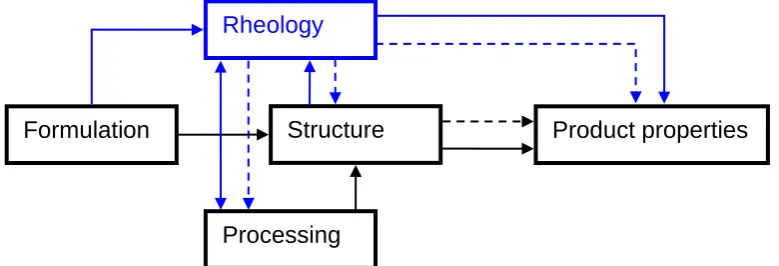
behaviour of starch polymer melts during processing is a key point in 1) 18
understanding the melt microstructure as affected by the processing conditions, 2) 19
solving fundamental flow-related engineering problems, 3) determining optimal 20
processing conditions, and 4) better controlling the quality of the final products. The 21
critical role of rheology in starch polymer processing is illustrated in Fig. 1. 22
23
[Insert Fig. 1 here] 24
The rheology of starch polymers, however, is not a simple issue. While water acts 1
as a destructuring agent and an efficient but volatile plasticiser during processing, 2
most rheometers cannot preserve the water content, which makes the rheological 3
measurements often impossible. Secondly, the massive macromolecular changes 4
under thermomechanical treatment during rheological measurement result in 5
subsequent changes in rheological properties which are difficult to follow. This is in 6
contrast to a standard synthetic polymer like polyethylene (PE), which is relatively 7
stable during processing and measurement. Thirdly, the viscosity of starch polymer 8
melt is much higher than that of most synthetic polymers, which also makes the 9
rheological characterisation difficult. The frequent use of different plasticisers and 10
additives for the purpose of reducing the viscosity and improving the processibility 11
further make the rheological properties of starch polymer melts difficult to understand. 12
In all, these difficulties have led to incorrect or missing information on processing 13
rheology of starch polymers, and this itself can be one of the biggest hurdles in the 14
development of new environmentally friendly starch polymeric materials. 15
Although starch polymers and their processing have already been well reviewed in 16
several papers [1,3-10], the rheological behaviour and the analysis of the rheology-17
processing relationships has not been a focus. This review reports on the state of the 18
art in the field of the rheology of starch polymers including the specially designed 19
rheometric techniques and the complex rheological behaviours as influenced by 20
different conditions. The backgrounds of starch fundamentals and processing are also 21
given. It is believed that a clear understanding of the rheological properties of starch 22
polymer melts is crucial in the processing for the next generations of low-moisture 23
starch-based foods and bioplastic materials. 24
2. Starch fundamentals
1
2.1. Structures of starch
2
The starch granule provides the main way of storing energy over long periods in 3
green plants [11]. Starch granules are mainly found in seeds, roots, and tubers, and 4
are from origins such as maize (corn), wheat, potato, and rice. Native starch granules 5
are well known to have multilevel structures from macro to molecular scales, i.e. 6
starch granules (<1 μm~100 μm), alternating amorphous and semicrystalline shells 7
(growth rings) (100~400 nm), crystalline and amorphous lamellae (periodicity) 8
(9~10 nm), and macromolecular chains (~nm) [11-14]. Native starch granules present 9
a concentric 3D architecture from the hilum with a total crystallinity varying from 10
15% to 45% depending on the particular plant species [15]. Starch is a polysaccharide 11
consisting of D-glucose units, referred to as homoglucan or glucopyranose. The two
12
major biomacromolecules of starch are amylose and amylopectin. Amylose is a 13
sparsely branched carbohydrate mainly based on α(1–4) bonds with a molecular 14
weight of 105–106 and can have a degree of polymerisation (DP) as high as 600 [11]. 15
The number of macromolecular configurations based on α(1–6) links is directly 16
proportional to the amylose molecular weight [16]. The chains show spiral-shaped 17
single- or double-helices with a rotation on the α(1–4) link and with six glucoses per 18
rotation, where the hydroxyl groups are mainly located toward the exterior of the 19
helices. On the other hand, amylopectin is a highly multiple-branched polymer with a 20
high molecular weight of 107–109. It is one of the largest natural polymers known 21
[11]. Amylopectin is based on α(1–4) (around 95%) and α(1–6) (around 5%) links, 22
with constituting branching points localised every 22–70 glucose units, generating a 23
kind of grape-branch-like structure with pending chains of DP ≈ 15. This specific 24
Besides, in starch granules are also found very small amounts of proteins, lipids and 1
phosphorus depending on the botanical resource [12,13]. These components can 2
interact with the carbohydrate chains during processing (e.g. Maillard reaction) and 3
then modify the behaviour of the starchy materials. The highly hydrophilic nature of 4
starch is by the cause of the abundance of hydroxyl groups in the polysaccharides by 5
genetic selection. 6
Depending on the source, amylose content of starch can be varied from <1% to 7
70%. The so-termed waxy starch contains little or no amylose, whereas high-amylose 8
starch contains >50% amylose. Tab. 1 gives an overview of the structural properties 9
of maize starches with different amylose contents [17]. Starches with different 10
amylose contents have quite different thermal, rheological, and processing properties. 11
12
[Insert Tab. 1 here] 13
14
2.2. Gelatinisation/melting of starch
15
When native starch granules are heated in water, their semicrystalline nature and 16
3D architecture are gradually disrupted, resulting in the phase transition from an 17
ordered granular structure into a disordered state in water, which is known as 18
“gelatinisation” [18-20]. Gelatinisation is an irreversible process that includes, in a 19
broad sense and in time/temperature sequence, granular swelling, native crystalline 20
melting (loss of birefringence) and molecular solubilisation [21]. Full gelatinisation 21
of starch under shearless conditions requires excess water, which Wang et al. [22] 22
have defined as >63% for waxy maize starch for example. If the water concentration 23
is too high, the crystallites in starch might be pulled apart by swelling, leaving none to 24
forces will be much less significant and the steric hindrance is high. Thus, complete 1
gelatinisation will not occur in the usual temperature range [23-25]. However, as the 2
temperature increases, starch molecules will become progressively more mobile and 3
eventually the crystalline regions will be destructured [26]. The process of 4
gelatinisation with a low water content could more accurately be defined as the 5
“melting” of starch [24]. 6
The gelatinisation/melting behaviour of starch is quite different when shear 7
treatment is imposed [27]. It has been shown that shear can enhance the 8
destructuration of starch granules in abundant water [28,29] and the melting of 9
crystallites with limited water [30-32]. The significance of such studies is that most 10
processing techniques for starch polymers involve shear treatment. In extrusion 11
processing, shear forces can physically tear apart the starch granules, allowing faster 12
transfer of water into the interior molecules [33]. Therefore, during extrusion, the loss 13
of crystallinity is not only caused by water penetration, but by the mechanical 14
disruption of molecular bonds due to the intense shear fields within the extruder [34-15
37]. 16
17
3. Starch processing
18
3.1. Processing strategies
19
The techniques that have been used to process starch polymers, such as internal 20
mixer, extrusion, injection moulding, compression moulding, and film casting, are 21
similar to those widely used for standard synthetic thermoplastics. Among these 22
techniques, extrusion is the most widely used. A single-screw extruder (SSE) can 23
handle the high viscosity of starch and provide a high processing pressure for 24
large operational flexibility (individual barrel zone temperature control, multiple 1
feeding/injection, and screw configuration for different degree of mixing/kneading) 2
and is useful for intensive mixing and compounding of components into starch 3
plastics. Another advantage of TSE is to allow the decoupling of die flow and 4
mechanical treatment. In both SSE and TSE, residence times and specific mechanical 5
energy (SME) inputs can be controlled, and high efficiency production can be 6
achieved. Other processing techniques such as film blowing and injection moulding 7
are often combined with extrusion. More details about the specifics of processing 8
techniques for starch polymers can be found in another review paper [1]. 9
Starch cannot be thermally processed without water. By reducing the moisture 10
content, the melting temperature of starch would progressively increase, and that of 11
dry starch is often larger than its decomposition temperature as extrapolated by Flory 12
Law [38,39]. Water functions by lowering the melting temperature and plasticising 13
the starch polymer. As a result, in practical processing, water acts as a “plasticiser”. 14
However, unstable processing may be caused due to the evaporation of water. Further, 15
the final products based on starch containing only water usually have poor mechanical 16
properties especially due to the brittleness since its final temperature is lower than its 17
glass transition temperature (Tg). To overcome these issues, non-volatile (at the
18
processing temperature) plasticisers such as polyols (glycerol, glycol, sorbitol, etc.) 19
[40-43] and compounds containing nitrogen (urea, ammonium derived, amines) 20
[43,44] are utilised. Also, citric acid [40] has been used as non-volatile plasticisers to 21
prepare TPS. 22
Various lubricants have been used to improve the processibility of starch 23
fluoro-elastomers [43]. The use of a lubricant during processing can reduce the 1
tendency of the material to stick to the die and clogging it. 2
To improve the product performances such as moisture resistibility, mechanical 3
properties, and long-term stability, starch is often blended with other (especially 4
biodegradable) polymers such as polylactide (PLA) [2,47-52], polycaprolactone (PCL) 5
[2,47,53,54], poly(butylene succinate adipate) (PBSA) [2,54], poly(hydroxy ester 6
ether) (PHEE) [55], and polyvinyl alcohol (PVA) [56,57]. 7
8
3.2. Issues related to processing
9
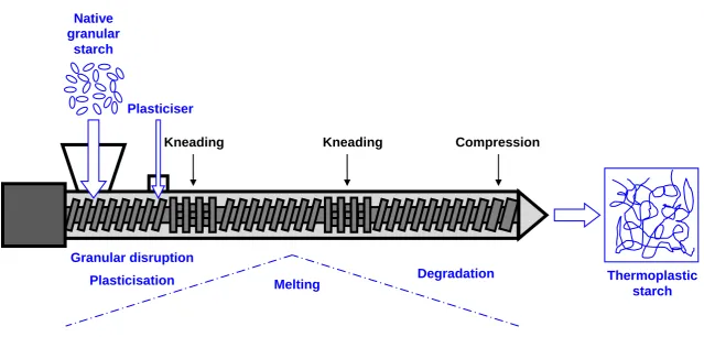
The processing of starch, however, is much more complex and difficult to control 10
than for many other polymers. Fig. 2 gives a schematic representation of starch 11
processing by extrusion. While the processing of most synthetic polymers constitutes 12
melting, blending/compounding, and shaping, the processing of starch also involves 13
the transformation (granular disruption, crystalline melting, etc.) of starch from a 14
native granular state to a molten state. To produce a homogeneous molten state, high 15
energy input (high SME, >102 kWh/t) is needed [58-60]. However, sometimes we 16
can observe residual granules in starch polymer melt [31,32,61], which means the 17
starch granular transformation is not 100%. In addition, Starch macromolecular 18
degradation under processing especially with the shear treatment has been studied 19
[24,62,63]. The level of degradation depends on the processing conditions and 20
formulation such as plasticiser type and content, temperature, and total SME 21
[62,64,65]. In addition, the processing can affect amylopectin much more than 22
amylose due to the large size, the highly branched structure, and the inflexible chains 23
which are influenced by the processing, can, in turn, impact the processibility 1
(rheology) and product properties. 2
3
[Insert Fig. 2 here] 4
5
4. Rheometry for starch polymers
6
Since high energy input (SME >102 kWh/t) is needed to obtain a homogeneous
7
molten state for rheological measurement, the number of rheometers used in the 8
studies of starch polymer melts is limited. Tab. 2 gives a comparison of these 9
rheometers and more details are as followed. 10
11
[Insert Tab. 2 here] 12
13
4.1. Backgrounds
14
Details in polymer rheology and rheometry can be found in a number of books 15
[68-71]. 16
Regarding the rheology of starch polymer melts, most literature has dealt with 17
steady shear viscosity (ηs), which can be measured by forcing a polymer melt through
18
a capillary/cylindrical die viscometer (CDV) or slit die viscometer (SDV) and 19
calculated based on the melt flow rate and the pressure drop across the die channel. A 20
SDV is preferably used since pressure transducers can be more easily flush-mounted 21
along the channel and thus pressure gradient (dP/dL) along the channel can be 22
obtained. In this case, the obtained result is more accurate than that from a CDV 23
where only inlet pressure is usually measured and the excess pressure drop is 24
Comparing with shear viscosity, extensional viscosity (ηe) has been much less
1
focused for starch polymers. It can be obtained from entrance pressure drop 2
measurement made on a CDV or SDV [74-76]. The entrance pressure can be 3
determined either from Bagley plots when a CDV is used, or by subtracting the 4
extruder barrel head pressure with the extrapolated pressure at the entrance of the die 5
when a SDV is used. Different analysis methods in extensional flow have been 6
compared for starch polymer melts [77,78]. It has been suggested that extensional 7
viscosity can be used to evaluate the elastic properties of polymer melts [71,74]. 8
Another way to evaluate the elasticity is to use first normal stress difference (N1),
9
which has also not been widely reported for starch polymer melts. It is defined as: 10
N1 = τ11 – τ22 (1)
11
where τ11 is the normal stress along the direction of flow, and τ22 is the normal stress
12
along the direction of the velocity gradient. An SDV can easily be adapted for the 13
measurement of N1 by exit pressure method [79] or hole pressure method [80-82]. In
14
the first method, since exit pressure is obtained by extrapolating the pressure 15
measurements along the die to the exit, both positive and negative values have been 16
obtained for starch polymer melts [77,83,84]. The erratic results can be ascribed to 17
such reasons as the under-developed flow or water evaporation-induced foaming at 18
the exit. It has been shown that the hole pressure method is more reliable than the exit 19
pressure method for starch polymer melts [85]. 20
21
4.2. “Off-line” rheometry
22
As previously stated (Section 3), the most efficient way to process starch is by 23
single-/twin-screw extrusion. After extrusion processing, the rheological properties of 24
“off-line” rheometry, understood as “off the initial extrusion processing line”. In 1
terms of the measurement principles, the category includes rotational rheometer, 2
plunger-type capillary/slit rheometer, and extruder-type capillary/slit rheometer. 3
4
4.2.1. Rotational rheometer
5
A rotational rheometer is a particular type of rheometer in which shear is produced 6
by a drag flow between a moving part and a fixed one, which forms such geometries 7
as plate-plate, cone-plate, and concentric cylinders [69]. The tested material is located 8
between the two parts and is exposed to the environment. Though this type of 9
rheometer has regularly been utilised to study the rheological properties of starch gels 10
or pastes (with high water content, > 95%) [86,87], it is quite difficult to use it for the 11
rheological measurements of starch polymer melts due to too low SME input, and 12
water evaporation at high temperature. In addition, the high viscosity of starch 13
polymer melts usually surpasses the torque capacity of such a rheometer. Della Valle 14
and Buleon [88] used a plate-plate geometry and coated the sample outer edge with 15
silicon grease to reduce the evaporation of water; however, the water evaporation was 16
still obvious as shown in time sweep test. Despite of the difficulty, this rheometer 17
remains to be an interesting tool, in some precise conditions, to study the properties of 18
some starchy materials. 19
20
4.2.2. Plunger-type capillary/slit rheometer
21
A plunger-type capillary/slit rheometer consists of a barrel where the material is 22
loaded, a plunger (also piston) for compressing and pushing the material, and a 23
capillary/slit die which is attached at the end of the barrel. After the material is loaded 24
die at a series of pre-selected speeds. The material is thus forced through the die 1
channel. The flow rate can be calculated with the plunger speed along with its 2
geometry data. The total pressure drop through the barrel and capillary can be 3
calculated with either the load on the plunger or a pressure transducer mounted on the 4
barrel. Alternatively in some latest designs (e.g. Instron® CEAST SmartRheo Series), 5
the dP/dL can be calculated by a series of pressure transducers flush-mounted through 6
a slit die channel. Consequently, shear rate and shear stress, and thus viscosity, can be 7
calculated. Particularly, some recent developed rheometers (e.g. Malvern® Rosand) 8
have twin-bore units which allows simultaneous measurements on both long and short 9
dies to determine the inlet pressure drop at the die, and therefore the absolute viscosity 10
by Bagley method. On the other hand, when some specially designed dies such as 11
zero-length die were used, the kind of rheometers can be employed to estimate the 12
extensional flow characteristics of polymer samples. 13
One of the greatest advantages of a plunger-type capillary/slit rheometer is their 14
wide range of shear rate, roughly between 2.5 × 10⁻¹ and 5 × 10⁴ s-1 according to the 15
literature [2,44,47,49-51]. Besides, the rheometer is easy to use and requires 16
relatively small amount of sample to be tested. Moreover, the material is subjected to 17
much less shear treatment when a plunger-type capillary/slit rheometer is used 18
compared to an extruder-type capillary/slit rheometer (discussed in the following 19
section) [89]. As a result, this rheometer has been widely used for the rheological 20
measurements of TPS prepared by extrusion processing [2,40,43-45,47,49-21
51,56,57,83,89-96]. 22
In some studies [97-99], this rheometer has been directly used as a processing tool, 23
in which native granular starch pre-blended with plasticiser is only applied with high 24
low or even absent, and that heat diffusion is not uniform. Thus, a homogeneous 1
molten state of starch can hardly be achieved like in extrusion processing. 2
A pre-shearing rheometer called “Rheoplast®” has been designed for the 3
rheological studies of starch polymer melts [100-103]. The schematic representation 4
of this rheometer is shown in Fig. 3. It combines the features of a Couette rotational 5
system, in which a mechanical treatment may be applied and the melting is executed, 6
and of a capillary rheometer in which the viscosity is measured. The main advantages 7
of the Rheoplast include [100,101]: 8
The material is subjected to a well characterised thermomechanical treatment 9
(under specific shear rate, melt temperature, and shearing time): The shear rate is 10
determined by the rotation rate of the inner piston; the melt temperature is 11
controlled by the circulation of a thermostated fluid through channels around the 12
barrel, and the shearing time is the time for which the inner piston is rotated. 13
The different parameters of treatment (shear rate, melt temperature, and shearing 14
time) are independent, unlike those of an extruder in which, for example, 15
increasing screw speed leads to the modification of residence time. 16
17
[Insert Fig. 3 here] 18
19
Vergnes et al. [101] claimed that Rheoplast can be as a useful tool for the 20
simulation of the processing in an extruder because the treatment intensity in the 21
Rheoplast (rotation speed: 200–700 rpm; melt temperature: 140–180°C; shearing time: 22
5–40 s) are of the same order of magnitude as those encountered in extrusion 23
viscometer is lower than that by Rheoplast due to the difference of SME leading to 1
different macromolecular degradation. 2
In operation, there are also some problems associated with the Rheoplast such as 3
the loss of moisture at high temperature and the tampering of measurement by the 4
remaining product in the convergent entry and the capillary itself [100]. To overcome 5
these issues, a number of repetitions are important for each value of the pushing-down 6
velocity of the inner piston (i.e. for each value of the flow rate through the capillary) 7
[100]. Bagley corrections are also critical and can be applied by using capillaries with 8
different length to radius (L/r) ratios [100,102,103]. 9
The Rheoplast can also be used as an off-line rheometer to test the rheological 10
properties of TPS prepared by other methods such as extrusion [103]. Moreover, it is 11
interesting to read in some literature [34,104] that this facility has also been used 12
solely as a processing tool without capillary. 13
14
4.2.3. Extruder-type capillary/slit rheometer
15
The extruder-type capillary/slit rheometer is actually a CDV or SDV incorporated 16
to an extruder which functions for remelting and feeding the material into the 17
viscometer. The extruder used here is mostly a SSE (choke-fed extruder) with a 18
compression screw [11,52,54,65,105-107]. The rotation of the screw forces the 19
material through the die rheometer and the shear rate can be varied with the screw 20
rotation speed. In this technique, either the Bagley method (for CDV) [65,95,108] or 21
the pressure gradient method (for CDV or SDV) [52,54,107,108] has been used to 22
measure the viscosity of starch polymer melts. 23
Due to the set-up, this technique usually requires a relatively large amount of 24
work more efficiently because the extrusion is carried out in a continuous way without 1
waiting time for sample melting. Besides, this technique is suitable when multiple 2
extrusion runs are required especially for TPS blends and composites [52,54]. 3
Furthermore, this technique also allows some post-extrusion processes such moisture 4
content conditioning to be carried out before the rheological measurements [65,108]. 5
The use of a separate extrusion run for rheological measurement, however, may 6
increase the macromolecular degradation especially with starch which is highly 7
sensitive to the thermomechanical history [65]. Therefore, the measured viscosity of 8
TPS by this method was usually lower than by an in-line extrusion rheometer 9
(discussed in Section 4.3) [43,84]. Besides, the change in screw speed for different 10
shear rates also changes the processing history, which results in different product to 11
be tested at different shear rate. However, in a some particular studies, the shear rate 12
was controlled by a speed-controlled piston in the die [106] or a side-stream valve at 13
the end of the extruder barrel [105], which greatly reduced the thermomechanical 14
history difference. Since the latter method has mostly been used in an in-line 15
rheometry, the details will be discussed in Section 4.3.2. 16
17
4.3. “In-line” rheometry
18
In contrast to the off-line rheometry, the “in-line” (also “on-line” in some 19
literature) rheometry allows the rheological measurements in the continuation of 20
processing. This can be achieved by incorporating an instrumented die rheometer at 21
the exit of the extruder [109]. This technique avoids any subsequent structural 22
changes and water loss during another rheological measurement run. 23
4.3.1. Single-channel die rheometer incorporated to an extruder
1
In this technique, either a CDV or SDV can be directly associated with an extruder 2
similar to the set-up in an off-line extruder-type rheometer. Both Bagley method 3
[55,110,111] and pressure gradient method [53,84,112-117] have been used for 4
viscosity measurements. Different shear rates can be achieved by varying the screw 5
speed for a choke fed extruder (SSE) [2,48,95,111,113-115,118], or by varying the 6
feed rate in a starve fed extruder (TSE) [53,55,64,83,84,93,110,116,117], both of 7
which changes the throughput of the extruder. Using both CDV and SDV may 8
achieve a wider range of shear rate [84,113]. Martin et al. [84] showed that shear rate 9
ranges of 1–103 s-1 and 102–104 s-1 could be obtained by using SDV and CDV
10
respectively. 11
Changing the throughput of extruder, however, also made the material to be 12
subjected to different thermomechanical treatments (SME and temperature) at 13
different shear rate settings. This can explain the strange results such as negative n
14
values obtained by some authors [114,119]. For twin screw extruders, this issue may 15
be addressed by controlling screw speed and feed rate simultaneously, to provide an 16
equal thermomechanical treatment during the process [117]. This, however, leads to a 17
very long and complex experimental procedure [120]. 18
Many studies have shown that the operation of the in-line viscometer has a 19
considerable effect on the rheological properties of starch [24,93,111,113,117,119] 20
due to the granular transformation and macromolecular degradation. To correct these 21
effects, some authors have proposed the viscosity models involving the dependence of 22
strain history [97], SME [84], and starch conversion [113], which could be extended 23
such as screw rotation speed [93] cannot be generalised for other systems. These 1
models are detailed in Section 5.1.6. 2
3
4.3.2. Double-channel die rheometer incorporated to an extruder
4
The main purpose of using a double-channel die (DCD) rheometer incorporated to 5
an extruder is to reduce or eliminate the interference between die measurement and 6
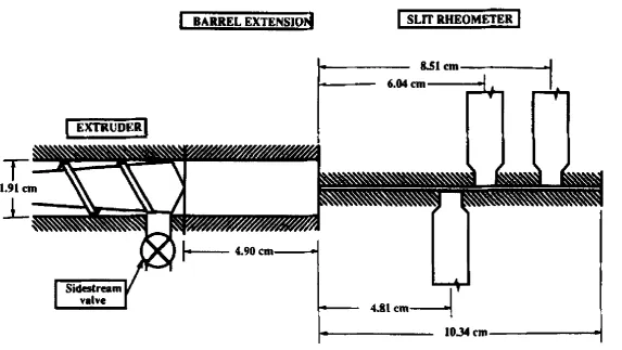
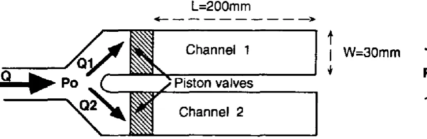
extruder operation. To this end, Padmanabhan and Bhattacharya [119] introduced an 7
idea of using a side-stream valve to vary the flow rate at the SDV, which has been 8
applied in a series of studies [77,78,85,121,122]. In this design, a side-stream valve 9
was placed near the exit of a SSE which was flood-fed at fixed screw speeds (cf. 10
Fig. 4). By adjusting the opening of the side-stream valve, the flow rate through the 11
slit die is controlled and the shear rate is varied. The rheological data obtained using 12
this technique (power law index n = 0.30–0.44 for moisture contents of 25–35%, die 13
temperatures of 160–180 °C, and screw speeds of 160–240 rpm) were significantly 14
different from those obtained by varying the screw speed, which for some conditions 15
yielded values of n < 0 [119]. They claimed that the side-stream valve can 16
significantly reduce the processing history effects on the rheological data and provide 17
a wide range of shear rate [119]. Similar idea has been applied with a TSE [123,124]. 18
However, with this technique, it seems difficult to maintain a constant total flow: 19
when the opening of the side stream valve is increased, there is no way to decrease the 20
opening of the SDV channel. This could result in the pressure variation and thus 21
changes in the extrusion conditions. 22
23
[Insert Fig. 4 here] 24
Based on the previously proposed principle by Springer et al. [125], an in-line 1
rheometer called “Rheopac” has been developed by Vergnes et al. [120] and used in 2
the rheological studies of starch polymer melts [58,126-129]. A schematic 3
representation of this rheometer is shown in Fig. 5. This rheometer can divide the 4
main flow of melt into two geometrically identical channels, one for the measurement 5
and the other for derivation. Each channel is provided with a piston valve, which can 6
be moved up and down to partially obstruct the flow section. It would thus be 7
possible to modify the flow rate in the first channel and to balance this variation in the 8
second channel, so that the entrance pressure remains constant. To achieve this, a 9
careful design is needed [120]. The relationship between the two valve openings is 10
determined by the n value. However, if a proper ratio between the valve and slit 11
lengths is chosen, and the n value of the melt is higher than 0.4, the dependence of 12
valve opening on the n value is weak [120]. 13
14
[Insert Fig. 5 here] 15
16
As a result of such design, the Rheopac permits the variation of the shear rate in 17
the measuring section without modifying the flow conditions along the extruder, so 18
that the material undergoes the same thermomechanical history. Another great 19
advantage of this rheometer is that measurements can be performed more swiftly than 20
with a classical slit die, since no waiting time for the stabilisation of the melt flow is 21
required after adjusting the piston height for different shear rate [120]. However, it 22
has been suggested that each channel of the Rheopac is only be partially obstructed by 23
the piston since starch overcooking and die fouling would happen in case of fully 24
Li et al. [130] also used an in-line SDV for the rheological study of TPS. There 1
was an adapter fitted between the SDV and the extruder to allow the diversion of flow. 2
Both the flow restriction towards the bypass channel and the one towards the SDV 3
could be controlled by two valves for each of them. By adjusting the openings of the 4
two valves, the flow rate in the SDV was varied to achieve different shear rate. 5
Instead of calculating the relationship between the two valve openings (which is used 6
for the Rheopac [120]), there was a pressure transducer mounted before the two 7
valves, which could be used to monitor and maintain the entrance pressure (P0) at a
8
constant value while adjusting the valve openings. Therefore, it possesses the merits 9
of the Rheopac while it is more convenient to use. 10
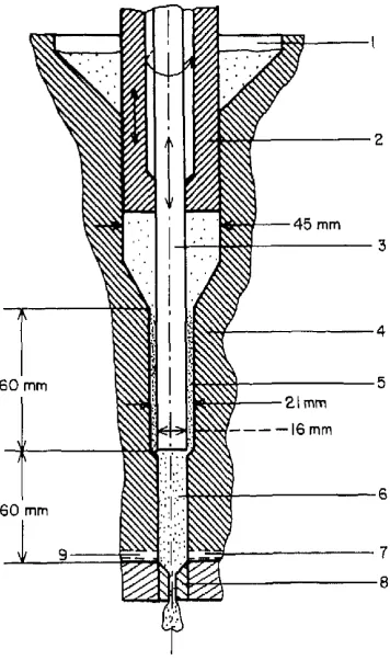
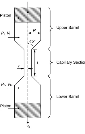
Drozdek et al. [131] used a specially designed dual-orifice capillary die (cf. Fig. 6) 11
which attached to a TSE to determine the n value of starch polymer melts. This die 12
enables two flow rates to be collected at one extruder condition. The radii of the two 13
capillaries are chosen so that the total cross-sectional area of the two branching 14
capillaries is the same as the cross-sectional area of the initial capillary to reduce 15
entrance flow effects. Each capillary has sufficient length to ensure the development 16
of fully developed laminar flow before the exit. The die can be maintained at constant 17
temperature for both capillaries. The power law index is then determined by the 18 equation: 19 S L S L S L L S r r Q Q r r L L n log 3 log log log
(2) 20
where L, r, and Q are respectively the length, radius, and volumetric flow rate of a 21
capillary, with the subscript “S” means the small one and “L” means the large one. 22
than any other in-line methods. However, due to the geometry restrictions, pressure 1
transducers at the entrance to the bifurcated flow channels and along these channels 2
was not possible, and therefore this rheometer was not suitable for the determination 3
of the K value. 4
5
[Insert Fig. 6 here] 6
7
4.4. Others types
8
Some special rheometers such as multipass rheometer (MPR) and mixer-type 9
rheometer can be utilised both to process native granular starch (with plasticiser) at 10
controlled thermomechanical conditions, which simulates temperature, high-shear, 11
and high-pressure conditions in an extruder, and to evaluate their rheological 12
properties. Therefore, they represent new types of rheometers for more convenient 13
and efficient rheological study of starch polymer melts. 14
15
4.4.1. Multipass rheometer
16
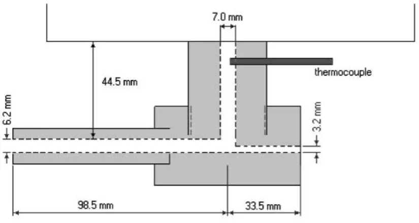
A multipass rheometer (MPR) has recently been developed for the rheological 17
measurements of liquids and polymer melts [132-134]. Tajuddin et al. [135], for the 18
first time, used a MPR for the study of rheological properties of TPS. Fig. 7 gives a 19
schematic representation of the MPR. It consists of a top and a bottom barrel in 20
which two servo-hydraulically driven pistons enter respectively. A capillary test 21
section is positioned between the barrels. The temperature of the barrels and capillary 22
can be accurately controlled, and the pressures in the barrel sections are monitored. 23
After introduction of the material, one piston will be moved toward the other until a 24
driven such that their separation remains constant. In “multipass steady” mode, the 1
pistons advance at constant velocity for a given time, yielding steady shear data. The 2
piston position is then held constant for a set dwell time and then the piston motion is 3
reversed. In this way, a multitude of successive steady flow measurements can be 4
made. Mean differential pressure can be calculated at certain piston speed. Bagley 5
correction can be applied by using capillaries with different L/r ratios [72]. Different 6
piston speeds are used for obtaining the result at a wide range of shear rates. Thus, 7
the viscosity can be calculated. 8
9
[Insert Fig. 7 here] 10
11
Compared to other conventional rheometers, the MPR has the advantages such as 12
the requirement of only a small amount (~20 g) of sample, the pressurisation of 13
sample, and the fully closed and sealed barrels. These allow MPR to be a suitable 14
tool to measure the rheological properties of TPS. 15
Native starch (pre-blended with plasticiser) can be processed by MPR under 16
determined pressure, temperature, and processing intensity (shear rate and time) [135], 17
which can be monitored by the decrease in viscosity with time. When the viscosity 18
reached a stable value, it is considered that the sample had achieved a stable state and 19
was ready for rheological measurements. This stable state is crucial otherwise 20
molecular degradation may continue to occur during measurement. 21
As a relatively new rheometer, MPR has not been fully employed for starch 22
polymer melts. Since MPR can also be operated in an oscillatory mode [133], it could 23
Furthermore, it has also proven useful in studying viscous conditions favouring 1
bubble growth in polymer melts [136]. 2
3
4.4.2. Mixer-type rheometer
4
It has been demonstrated that, by using an internal mixer with a closed chamber 5
(Haake Rheomix®), TPS can be prepared under defined thermomechanical conditions, 6
and its rheological behaviour can be monitored in real time [31,32,52,137]. The 7
mixer used in the reports has three temperature-controlled barrels. It can be 8
incorporated with different types of twin rotors such as roller rotors. The volume of 9
the chamber with the rotors is 69 cm3. The material can be loaded into the chamber
10
through a hopper on the top of the middle barrel, followed by compression and sealing 11
with a plunger. According to the manufacturer, better mixing is achieved in starved 12
conditions; however, for restraining the water evaporation and better shear treatment 13
of starch, maximum filling of the chamber need to be ensured. During measurement, 14
motor torque, barrel and material temperature are recorded as a function of time 15
[31,32,52]. Additionally, a pressure transducer can be fixed on the front part of the 16
chamber to enable the pressure measurement inside the chamber [137]. 17
In some studies [31,32,52], such a mixer was used to investigate the 18
transformation of native granular starch into a thermoplastic form, which could be 19
followed by the change in torque with time. When the torque value reached a stable 20
value, it was considered that a stable state of TPS is achieved under specific 21
processing conditions (initial temperature and rotor speed). In another study [137], 22
the focus was on the rheological properties of TPS fully developed in the mixer under 23
different moisture and temperature conditions. In order to convert the torque into a 24
characterised molten polymer was used and the empirical correlation through a 1
classical least square procedure is practised. An alternative method involves the 2
assumption of the flow in the Rheomix device to be in a double Couette system [138]. 3
It has been reported that, though wide shear rate range (10–1000 s-1) could be 4
obtained by Rheomix, heat generated by viscous dissipation in high shear rate range 5
can hardly be evacuated through the chamber cooling system, and this may result in 6
large discrepancies on the results [137]. 7
8
5. Processing rheology of starch polymeric materials
9
5.1. Steady shear viscosity
10
Steady shear viscosity is the most prevalently measured rheological property of 11
starch polymer melts. This is because practical production requires the understanding 12
of melt flow curve of the material. Based on a scrutiny of the literature in this topic, 13
the dependence of shear viscosity of starch polymer melt on shear rate has generally 14
been considered in a power-law relationship, which can be expressed in the equation: 15
1
n
s K
(3)
16
where is the shear rate and K is the consistency coefficient. The n value lower than 17
1 means the shear thinning behaviour of starch polymer melts, which is mainly 18
ascribed to the gradual reduction of molecular entanglement at increased shear rate. 19
The more the n value approaches 1, the more the melt behaves like a Newtonian fluid, 20
which means it is less sensitive to shear rate. Based on Eq. 3, many authors have 21
focused on the effects of those formulation (plasticiser type and content) and 22
processing parameters (SME, temperature, etc.) on n and K in their studies. Thus, 23
different empirical equations describing n and K based on different systems have been 24
direct comparisons of these models especially their constants due to the differences of 1
samples and measurement methods and conditions. Therefore, the effects of 2
thermomechanical treatment, temperature, plasticiser/additive, starch type/structure, 3
additives, and blends/composites will be discussed in detail respectively in the 4
following sections. Then, the shear viscosity models will be further discussed. 5
6
[Insert Tab. 3 Here] 7
8
5.1.1. Effect of thermomechanical treatment
9
During processing, starch could undergo different degrees of granular 10
transformation and of macromolecular degradation under thermomechanical treatment; 11
thus, actually different products with different rheological properties may be obtained. 12
To understand the effects of processing on the shear viscous properties of starch 13
polymer melts, in-line methods have been most frequently utilised 14
[58,77,84,93,97,111-113,117,119,120,123,126,127,129-131]. Besides, pre-shearing 15
[100] and off-line rheometers [106] have also been used. 16
It has been reported that increasing the screw speed could reduce the melt 17
viscosity for both in-line [93,112,123] and offline [106] rheometric systems. 18
Particularly, when a TSE was used (shear rate was controlled by the feed rate), the 19
increase in screw speed, though reduces the degree of fill and the mean residence time, 20
increases the intensity of mechanical treatment, which results in greater granular 21
transformation and macromolecular degradation and thus lower melt viscosity; and 22
this mechanical treatment was more important at lower temperature [93]. Besides, an 23
increase in feed rate for TSE can also provide a greater thermomechanical treatment 24
when the feed rate is too high, the thermomechanical energy that a specific amount of 1
material received would reduce, resulting in a lower degree of starch transformation 2
and thus higher viscosity [130]. 3
In contrast to the screw speed, feed rate, SME has been much more preferably 4
used to evaluate the effect of thermomechanical treatment on the changes in starch 5
because SME can be a combined effect manipulated by the screw speed and feed rate. 6
According to the literature [93,126,129], when a TSE is used, higher screw speed (N), 7
lower feed rate (Q), or higher N/Q can lead to higher SME. Besides, screw profile can 8
also have impact on SME. The screw with more shearing and kneading elements 9
would definitely provide a greater SME during processing [106,126]. Furthermore, it 10
should be expected that different pattern of change in SME as a function of N/Q can 11
be generated when different screw profile is used. As observed by Berzin and 12
Tighzert [129], while SME was increased by increasing the N/Q ratio, the effect of 13
N/Q was more important when a more restrictive screw profile was used. However, 14
one should bear in mind that SME (= Γ × N/Q) cannot be well defined because it 15
contains a variable (torque Γ) that is not truly independent and related to the shear 16
viscous properties of the melt [130]. 17
It has been unanimously agreed that higher SME input can result in a greater 18
starch granular transformation and macromolecular degradation (as demonstrated by 19
intrinsic viscosity and SEC profile) [58,106,120,127,129], both of which lead to the 20
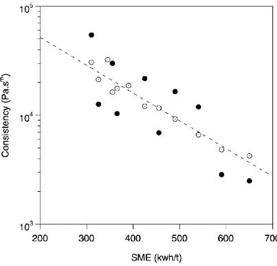
decreased viscosity of starch polymer melt. Martin et al. [84] observed a linear 21
relationship between K and SME in a single-logarithmic plot [Fig. 8]. However, the 22
manner in which SME influences viscous properties can be different under different 23
conditions. Using a pre-shearing rheometer for starch with 28% moisture content and 24
higher SME led to a lower viscosity (lower K value), the n value was not affected. 1
They also observed that the effect of thermomechanical treatment is more or less 2
marked according to the temperature [100]. In another study where a Rheopac 3
rheometer incorporated to a TSE was used, Vergnes et al. [120] reported that a 4
change in SME from 180 to 241 kWh/t by varying the feed rate can result in the great 5
changes in both K from 9050 to 2610 Pa.sn and n from 0.35 to 0.52 for the TPS at 6
moisture content of 16.7% and temperature of 190 °C. 7
8
[Insert Fig. 8 here] 9
10
To account for the discrepancies mentioned above, it needs to be stated that SME 11
may not be (though commonly has been) taken as the sole indication of the degree of 12
thermomechanical modification of starch polymer melt during extrusion. As observed 13
by Li et al. [130] with a DCD incorporated to a TSE, the degree of starch 14
gelatinisation, and the melt viscosity remained unchanged even though torque and 15
SME increased with the increase in screw speed at a constant degree of fill. This 16
increase in SME, however, was counterbalanced by a decrease in “specific thermal 17
energy” because residence time decreased with increasing screw speed at a constant 18
barrel temperature. 19
20
5.1.2. Effect of temperature
21
By using an in-line system, some authors have studied the effect of temperature 22
during processing, which can affect the changes in starch, and thus the melt viscosity. 23
For example, Li et al. [113] found that the maximum apparent viscosity occurred at 24
increase in melt viscosity at ≤ 130 °C is due to the increase in starch gelatinisation, 1
whereas the decrease in the melt viscosity at ≥ 130 °C indicated that starch 2
degradation occurred. Here, it needs to be pointed out that, in most studies by an in-3
line system, it is difficult to differentiate the effect of temperature on starch granular 4
transformation and macromolecular degradation and their effects directly on reducing 5
the viscosity of starch as a polymer. Furthermore, when reading the literature on the 6
in-line rheology of TPS, one should take note of what kind of temperature was used as 7
a varied parameter: the temperature at the last barrel zone(s) and die (processing 8
temperature) [93,112,119,130], or the melt temperature at the die channel (testing 9
temperature) [58,84,113,120,127,129,131]. In the former case, the melt temperature 10
may be higher than the controlled temperature because of the viscous dissipation 11
(discussed in Section 5.4). Thus, misleading rheological results may be generated. In 12
the latter case, it was common to achieve different desired melt temperatures by 13
varying the temperatures of barrel zones and die, of which the details, however, were 14
often missing. On the other hand, it is a remarkable that, even if an off-line system is 15
used, the temperature of the second measurement run may still have some 16
“processing” effect. Willett et al. [108] indicated that, when the measurement 17
temperature was high (160 or 180 °C), significant macromolecular degradation could 18
occur during the testing phase, to the point that any effects of starting materials were 19
eliminated. 20
In the following in this section, the temperature effect on melt viscosity in terms 21
of thermal activation of melt flow will be discussed. It is well known that an increase 22
in temperature would result in a lower viscosity of starch polymer melt. According to 23
Eq. 3, this can be reflected by a lower value of K at higher temperature as widely 24
116,118,120,122,127,129,135,137,139]. However, there have been discrepancies 1
over the effect of temperature on the n value. In some especially early studies 2
[99,108,110,113,114,116,118,129,137,139], the n was assumed to be a constant in the 3
shear viscosity models; thus, the effect of temperature on n was not elaborated. By 4
drawing the shear viscosity versus shear rate curve in a double-logarithmic plot, other 5
researchers observed that an increase in temperature would cause a higher n value 6
[58,65,94,100,107,115,122,127,135]. The same trend has been observed for 7
starch/PLA blends [49-51]. In the meantime, there have been reports showing that no 8
clear influence of temperature on n for starch polymer melts [44,84]. 9
The relationship between temperature and n may be complex when starch is 10
plasticised with different plasticisers and/or blended with other materials. Yu et al. 11
[40] studied the shear viscous properties of TPS plasticised with 30% glycerol content 12
without or with the addition of citric acid (1 or 3%). The results indicated that, while 13
temperature from 130 to 150 °C slightly increased the n value without or with 3% 14
citric acid, there was an apparent reverse trend for TPS with 1% citric acid. By using 15
the same TPS samples but blended with low linear density polyethylene (LLDPE), 16
Wang et al. [91] found that, when temperature increased from 130 to 150 °C, the n
17
value decreased for the blend without citric acid, but first increased and then 18
decreased for the blends with 1 and 3% citric acid. In another study by Ma et al. [90], 19
while an increase in temperature from 110 to 130 °C led to a great increase in n value 20
for TPS plasticised by formamide and urea mixture, a decrease in n with increasing 21
temperature was observed for the same sample but filled by 10% fly ash. The authors 22
didn’t further analyse these phenomena however. It could be possible that shear 23
interactions among starch, plasticiser, and the other polymer. This will further be 1
discussed in the following sections. 2
3
5.1.3. Effect of plasticiser/additive
4
Plasticisers usually have a large influence on the shear viscous properties of starch 5
polymer melts. In most cases, plasticiser is blended into native granular starch before 6
processing. As a result, the plasticiser content would not only influence the granular 7
transformation and macromolecular degradation during processing, which affect the 8
viscosity, but also assist the movements between starch inter- and intra- molecular 9
chains, which reduce the viscosity as well. Particularly, Willett and co-workers 10
[65,108] was able to separately determine the effects of moisture content during 11
processing and during measurement by using an off-line system. In one study [108], 12
starch was pelletised at different moisture contents during the first run and then 13
equilibrated to the same moisture content for shear viscosity measurements. It was 14
shown that moisture content during the pelletising step had a significant impact on 15
melt viscosity when tested at low temperature (110 or 130 °C): the TPS sample 16
pelletised with 15% moisture content had the lowest viscosity, that pelletised with 17
20% moisture content had the highest, while that pelletised at 30% moisture content 18
had an intermediate value. The reasons could be that the high melt viscosity (during 19
processing) at 15% moisture content caused more shear stress and more chain scission, 20
while water catalysed hydrolysis might occur with high moisture content (30%). In 21
the other studies [65,108], TPS pellets were prepared at the same moisture content and 22
subsequently equilibrated them to different moisture contents for shear viscosity 23
Apart from the effect on starch granular transformation during processing, an 1
increase in plasticiser content would decrease the viscosity of starch polymer melt 2
since it can decrease the polymer entanglement density and increase the ease of 3
disentanglement. It has been well demonstrated that a higher amount of water would 4
result in a lower K value [57,58,65,84,93,94,99,100,107,108,110,111,113-5
119,122,127,129,137,139,140]. However, the effect of moisture content on the n was 6
unknown in many studies since it was taken as a constant for modelling 7
[57,93,99,110,113,114,116-119,129,137,139,140]. In other reports where the n values 8
were shown at different moisture content, an increase in n with increasing moisture 9
content was mostly observed [58,65,94,100,107,111,115,127] although there have 10
also been reports where no evident trend of n with the change in moisture content 11
could be justified [45,84,122,131]. 12
As a frequently used plasticiser for starch, glycerol reduces the viscosity of starch 13
polymer melts as evidenced by a lower K value [41,106]. The impact of glycerol 14
content on n, however, has been in disagreement especially based on the limited 15
published data. While Thunwall et al. [96] reported an unchanged n value with 16
increasing glycerol content for hydroxypropylated oxidised potato starch, Rodriguez-17
Gonzalez et al. [41] observed a higher glycerol content slightly reduced the n value 18
for wheat starch. Regarding the latter result, it could be possible that when the 19
glycerol content is lower, less degree of starch granular transformation occurs during 20
processing, and the remnant large amount of starch granules make the fluid behave 21
more like a filled polymer melt. As a result, higher n value is displayed. Otherwise, a 22
higher n value should be expected with increasing glycerol content, and this has been 23
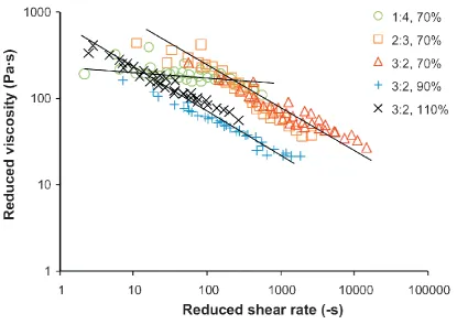
By MPR, Tajuddin et al. [135] investigated the shear viscous properties of well 1
transformed waxy TPS melts plasticised by both water and glycerol. The results 2
showed that an increase in glycerol/water ratio (1:4, 2:3, and 3:2) resulted in a 3
stronger shear-thinning behaviour; however, total plasticiser content (70–110%) had 4
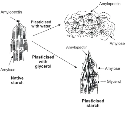
little influence on n (cf. Fig. 9). It was thus proposed that, different structural 5
characteristics can result with different plasticiser (cf. Fig. 10): when plasticised 6
mainly by water, amylopectin molecule has a compact ellipsoidal conformation by 7
greatly unfolding their branches, and these “ellipsoids” are easy to move, so more 8
Newtonian-like behaviour is shown; the “ellipsoids”, however, are largely absent 9
when glycerol is the main plasticiser, and the amylopectin molecules behave more 10
like a standard polymer and show stronger shear-thinning behaviour. 11
12
[Insert Fig. 9 here] 13
[Insert Fig. 10 here] 14
15
Many other low molecular weight substances such as citric acid, formamide, and 16
urea have also been utilised as plasticisers for starch. Citric acid can form stronger 17
hydrogen bonding interactions with starch molecules than glycerol [40]. It weakens 18
the interaction of starch molecules and improves the plasticisation of starch [91]. 19
Further, it may also depolymerise starch molecules during processing [49]. As a 20
result, citric acid can obvious reduce the viscosity of starch polymer melts, though its 21
effect on n has not been well understood [40,49,91]. On the other hand, plasticisers 22
such as formamide and urea are also effective plasticisers since their amide groups 23
enable them to form strong hydrogen bonds with starch and to break the existing 24
used to plasticise starch even without water [51,92]. Wang and co-workers [51,92] 1
examined the effect of formamide/glycerol ratio on the shear viscosity of TPS at fixed 2
total plasticiser content, and showed that an increase of formamide/glycerol ratio 3
decreased the K value but increased the n value. Nevertheless, when 30% (dry basis) 4
of the mixture of formamide and urea was used as plasticiser, TPS could have a 5
higher shear viscosity and a lower n value than that plasticised by the same amount of 6
glycerol [90]. In another study, with the increase of formamide-urea mixture from 30 7
to 50%, the n value first decreased and then increased [44]. Considering the whole of 8
the mixture plasticiser could be effectively bound to starch at 40% level [44], it can be 9
considered that, before 40%, the increase of plasticiser content resulted in more 10
hydrogen bonds which reduced the “ellipsoids” in starch and cause a stronger shear 11
thinning behaviour (cf. Fig. 10); however, when the plasticiser content was higher 12
than 40%, the excess of plasticiser reversed the trend due to its Newtonian behaviour. 13
Moreover, the authors of all these studies have shown that the use and higher content 14
of formamide, urea, and/or citric acid comparing with glycerol could generally cause 15
a decrease in flow activation energy (E/R, cf. Eq. 4 in Section 5.1.6), indicating less 16
temperature-sensitivity of TPS plasticised by these plasticisers [40,44,49,51,90-92]. 17
Willett et al. [108] investigated the effects of various low molecular weight 18
additives such as urea, lecithin, triethylene glycol (TEG), glycerol monostearate 19
(GMS), and polyoxyethylene stearate (POES) on the shear viscosity of TPS, and the 20
results are summarised in Tab. 4. It was found that all additives except GMS 21
significantly lowered the melt viscosity of TPS, with lecithin and POES exhibiting the 22
greatest efficiency (decreasing K and increasing n), though lecithin could effectively 23
reduce the molecular degradation of starch as well. Relative to the melt with 15% 24
water at reducing viscosity, which can be ascribed to the strong interactions between 1
these additives and starch molecules. The melt viscosity with GMS was essentially 2
the same as, or slightly higher than, those of starch/water, and this behaviour could be 3
attributed to the presence of unmelted amylose–lipid complexes in the melt. Though 4
amylose–lipid complexes could also form in the samples plasticised by lecithin and 5
POES, they were most likely melted at the testing temperature (160 °C) and thus had 6
no apparent effects on the rheological results. 7
8
[Insert Tab. 4 here] 9
10
Yu et al. [141] found that the addition of 10% urea, glycerol, sugar, KI, or NaCl to 11
TPS containing 30% moisture content was not as efficient as increasing the moisture 12
content from 30% to 40% in decreasing the viscosity. These results suggest that these 13
additives have weaker capacity to form hydrogen bonds with starch and to facilitate 14
starch molecular movements than water. 15
Supercritical carbon dioxide (sc-CO2), which has been considered as a novel
16
plasticiser in extrusion processing [142], also has an impact on the rheological 17
properties of starch polymer melts. Recently studies [124,143] have shown that the 18
use of sc-CO2 during extrusion processing lead to a lower K and a higher n for TPS
19
melt. This is because sc-CO2 can solvate starch molecules and reduce polymer
20
entanglement and subsequently decreased shear-thinning behaviour and viscosity. As 21
a result, sc-CO2 has a great potential for improving the processibility of starch
22
polymer melt. 23
Though a lubricant is an important additive in practical processing of starch 24