Fall 2018
Multicasting in Network Function Virtualization (NFV)
Multicasting in Network Function Virtualization (NFV)
Environment
Environment
Manika Dhingra
Iowa State University, [email protected]
Follow this and additional works at: https://lib.dr.iastate.edu/creativecomponents Part of the Digital Communications and Networking Commons
Recommended Citation Recommended Citation
Dhingra, Manika, "Multicasting in Network Function Virtualization (NFV) Environment" (2018). Creative Components. 53.
https://lib.dr.iastate.edu/creativecomponents/53
by
Manika Dhingra
A report submitted to the graduate faculty
in partial fulfillment of the requirements for the degree of
MASTER OF SCIENCE
Major: Computer Engineering
Program of Study Committee: Dr. Ahmed Kamal, Major Professor
The student author, whose presentation of the scholarship herein was approved by the program of study committee, is solely responsible for the content of this report. The
Graduate College will ensure this report is globally accessible and will not permit alterations after a degree is conferred.
Iowa State University
Ames, Iowa
2018
TABLE OF CONTENTS
Page
LIST OF FIGURES ... iii
LIST OF TABLES ... iv
ABSTRACT ... v
CHAPTER 1. INTRODUCTION: ... 6
Network Function Virtualization (NFV) ... 6
Software Defined Networking (SDN) ... 7
Multicasting ... 8
CHAPTER 2. IMPLEMENTION:. ... 10
Multicasting in star, tree and ring topologies ... 11
Adding Delay in Links. ... 14
NSFNET Topology ... 16
Arpanet Topology ... 18
Cost239 Topology ... 20
Random12 Topology ... 22
CHAPTER 3. CONCLUSION:. ... 25
LIST OF FIGURES
Page
Figure 1: The Software-Defined Networking (SDN) Framework………..….8
Figure 2:Example of service chaining in multicasting ... 9
Figure 3(a): Star Topology. ... 11
Figure 3(b): Flows for multicasting in star topology. ... 11
Figure 3(c): Ping result of multicasting ... 11
Figure 4(a): Tree Topology. ... 12
Figure 4(b): Flows for multicasting in Tree topology. ... 12
Figure 4(c): Ping resultof multicasting ... 12
Figure 5(a): Ring Topology. ... 13
Figure 5(b): Ring topology Python Code. ... 13
Figure 5(c): Flows for multicasting in Ring topology. ... 13
Figure 5(d): Ping result of multicasting ... 13
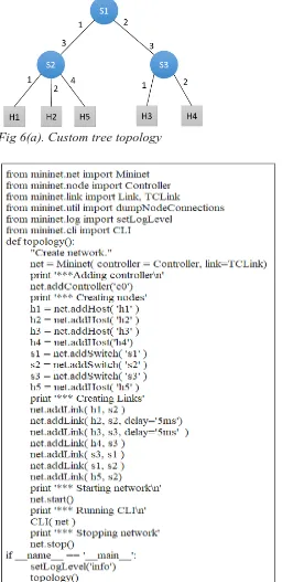
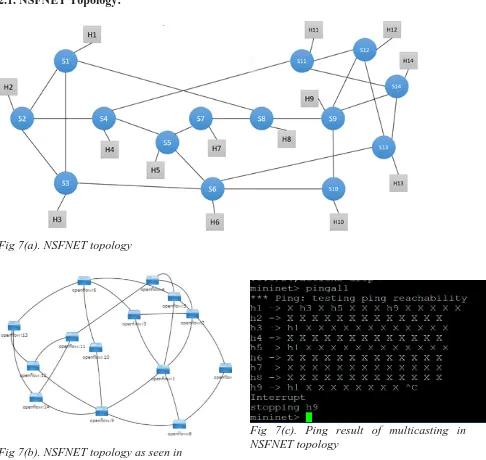
Figure 6(a): Custom tree topology. ... 14
Figure 6(b): Custom tree topology Python Code. ... 14
Figure 6(c): Ping delay without link delay. ... 15
Figure 6(d): Ping delay with link delay. ... 15
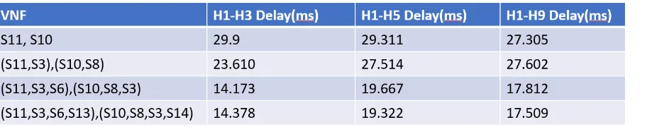
Figure 7(a): NSFNET topology. ... 16
Figure 7(b): NSFNET topology as seen in OpenDaylight Controller. ... 16
Figure 7(c): Ping result of multicasting in NSFNET topology ... 16
Figure 7(d): Delay vs number of VNFs graph for NSFNET network. ... 18
Figure 8(a): Arpanet topology. ... 18
Figure 8(b): Arpanet topology as seen in OpenDaylight Controller. ... 18
Figure 8(c): Ping result of multicasting in Arpanet topology ... 18
Figure 8(d): Delay vs number of VNFs graph for Arpanet network. ... 20
Figure 9(a): Cost239 topology. ... 20
Figure 9(b): Cost239 topology as seen in OpenDaylight Controller. ... 20
Figure 9(c): Ping result of multicasting in Cost239 topology... 20
Figure 9(d): Delay vs number of VNFs graph for Cost239 network. ... 22
Figure 10(a): Random12 topology. ... 22
Figure 10(b): Random12 topology as seen in OpenDaylight Controller. ... 23
Figure 10(c): Ping result of multicasting in Random12 topology ... 23
LIST OF TABLES
Page
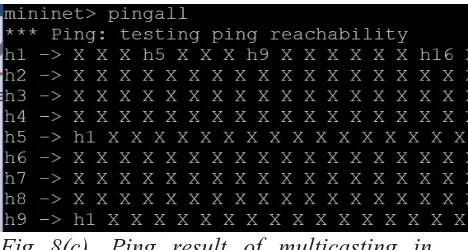
Table 1. Delay for different placements of VNFs in the NSFNET network. ... 17
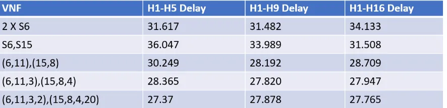
Table 2. Delay for different placements of VNFs in the Arpanet network. ... 19
Table 3. Delay for different placements of VNFs in the Cost239 topology. ... 21
ABSTRACT
Network Function Virtualization is a growing concept in the research field because of its
ability to decouple network functions, like network address translation (NAT), domain
name service (DNS), firewall, intrusion detection (IDS) etc., from proprietary hardware
equipment. They can now run in software making the network more flexible and agile.
This also reduces hardware and maintenance costs of the network. Nowadays many
applications use multicasting as it saves a huge amount of communication bandwidth. But
many packets need intermediary processing before reaching their destinations. For this
processing, Virtual Network functions (VNFs) are implemented in the network where
processing of packets takes place. Because of this the path through which the packets
traverse changes, and delay increases. This project considers different number and
placements of VNFs in four real-world topologies namely NSFNET, Cost239, Arpanet and
Random12, and observes the delay for every case. As the VNFs are duplicated on different
nodes in the network, the cost of deployment and maintenance of VNFs is increased, but
the delay decreases up to a certain number of VNFs. After this, the delay becomes constant.
CHAPTER 1. INTRODUCTION:
The project uses concepts like Network functions virtualization (NFV), Software Defined Networking (SDN) and multicasting in NFV-SDN environment. This section explains these concepts.
Network functions virtualization (NFV)
Network functions virtualization (NFV) enables software to run on commercial off-the-shelf (COTS) servers instead of dedicated network appliances like routers, switches and firewalls. Because of NFV, network operations are also improvised as network function software is dynamically instantiated as required in different locations in the network and installing new equipment is no longer required.
This makes NFV a catalyst for a significant paradigm shift in the networking and communication industry. It substantially reduces hardware costs by replacing dedicated equipment with shared servers. Apart from hardware costs, operational costs are also reduced with lesser appliances to maintain and deploy. It is also reduced because of the on-demand pay as you go deployment model. NFV also considerably increases the speed by which revenue-generating services can be brought to market. NFV provides flexibility and agility in the network along with the ability to innovate by turning network edge into a factory for virtual network functions (VNFs).
Three main components of NFV Framework are Virtualized network functions (VNFs), Network functions virtualization infrastructure (NFVI) and Network functions virtualization management and orchestration architectural framework (NFV-MANO Architectural Framework). VNFs are basically network functions implemented in a software form and deployed on NFVI. The NFVI consists of all hardware and software components of the environment where VNFs are deployed. NFVI can traverse multiple locations and the network between these locations is also part of NFVI. The last component of the framework is NFV-MANO which consists of functional blocks, data repositories used by them, interfaces and reference points by which they communicate for managing and orchestrating NFVI and VNFs.
NFV platform is the building block for NFVI and NFV-MANO. The NFVI role is composed of physical and virtual processing and storage resources, along with virtualization software. The NFV-MANO role involves VNF and NFVI managers and virtualization software operating on a hardware controller. The NFV platform makes carrier-grade features that manage and monitor the platform components, provide security and recover from failures, all these are important for public carrier network.
chain. This service is executed on demand depending on dynamic policy settings.
Commonly used network functions are Network switching elements like Broadband Network Gateway (BNG), carrier grade NAT; Mobile network devices like Home Location Register/Home Subscriber Server (HLR/HSS), NodeB and Evolved Node B (eNodeB); Virtualized home environments; Application-level optimization devices like Content Delivery Network (CDNs), load balancers; Traffic analysis elements like Deep Packet Inspection (DPI); Tunneling gateway devices like IPSec/SSL virtual private network gateways; Network security devices like Firewalls, intrusion detection systems, DOS attack detector etc.
The major advantage of using NFV that it also supports the co-existence of multi-tenancy of network and service functions, thereby allowing the usage of one physical platform for different services, applications, and tenants.
Software Defined Networking (SDN)
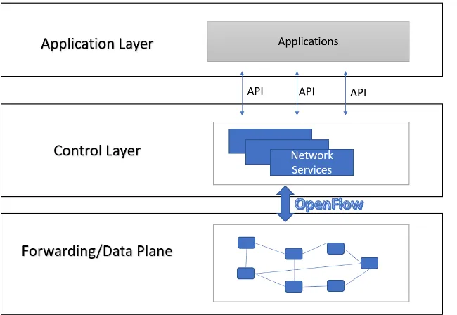
Software Defined Networking (SDN) makes a network logically centralized, open and programmable. The centralized control console in SDN enables cloud computing. By this, network engineers and administrators are able to respond to changing business requirements in a much quicker manner. SDN brings flexibility and agility in the network by encompassing different kinds of network topologies. This supports the virtualized server and storage infrastructure of the modern datacenter. SDN introduced the approach to design, build and maintain networks that separates the control plane and data plane. Control plane is the brain and data plane is the muscle of the network. This enables the network control to be directly programmable and the infrastructure can be abstracted for various applications and network services for applications as SDN cloud computing or mobile networks.
The simplest form of SDN architecture can be seen in the Figure 1. The basic idea of SDN is to separate control logic to off-device computer resources. The architecture consists of an SDN Controller, Southbound APIs and Northbound APIs. Controllers are the brains of the network because they give a centralized view of the overall network and this enables network administrators to dictate how forwarding plane should handle network traffic to the underlying infrastructure which is mainly composed of forwarding devices like switches and routers. This communication between controller and forwarding devices uses southbound APIs. OpenFlow is the most common standard protocol for this. Northbound APIs on the other hand are used for the communication of control layer with applications and business logic. This enables administrators to programmatically shape traffic and deploy services.
and the need for dedicated hardware and complex labor is eliminated. With SDN, NFV enables real-time and dynamic function provisioning along with flexible traffic forwarding.
Fig 1 The Software-Defined Networking (SDN) Framework
Multicasting
Multicasting is the technique of sending packets to multiple destinations simultaneously. In this kind of communication, packets sent may have to be duplicated in routers and then forwarded to multiple output ports based on the multicast topology. Multicasting saves a lot of bandwidth because in unicast, a single path is set up for each source-destination pair which is not the case here. Because of this multicast communication is getting increasingly popular. A lot of web-based applications use multicasting like video conferencing, software updates, multimedia distribution and IPTV.
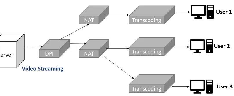
In every router, multicast packets are duplicated and forwarded to multiple ports according to the topology. As compared to unicast, transmission capacity is considerably reduced as a single path for every source destination is not required. Although SDN provides efficient and flexible implementation of multicast mechanisms, many multicast services today like video streaming require multicast communication that involve intermediary network functions such as deep packet inspection and video transcoding. In this scenario, Network Function Virtualization (NFV) enables efficient implementation of multicast services that involve intermediary processing.
Fig 2 Example of service chaining in multicasting
CHAPTER 2. IMPLEMENTATION:
This project uses emulation for implementing different network topologies and the tool, Mininet is used for that purpose. It is a network emulator that can build a network consisting of virtual nodes like hosts, switches, controllers, and connects them using links. The hosts run standard Linux network software, and the switches support OpenFlow for the communication with controllers in Software-Defined Networking environments.
Mininet is a great tool for research, development, learning, prototyping, testing, debugging etc.
Mininet provides a testbed for developing OpenFlow applications. It consists of a topology aware command line interface for running network tests. It can be used to create custom topologies using the Python based API.
The OpenDaylight (ODL) Controller is one of the most popular controllers, and gets its framework from ODL project which is open-source and industry supported SDN project hosted by The Linux Foundation. ODL project is aimed at promoting software-defined networking (SDN) and network function virtualization (NFV).
In this project, Mininet tool is used to enable multicasting on different topologies using the OpenDaylight controller. The packets before reaching their respective destinations should go through the VNFs where they are processed by different functions like Firewall, Load Balancers etc. These VNFs are implemented on different hosts in the network, but Mininet doesn’t allow hosts to forward packets. Therefore, for the purpose of simulation, they were implemented on different switches in the network. Delay in the links is added to implement the processing times of the network functions (VNFs). Different systems used in the project consists of 2 network functions placed on one or different switches and are then duplicated on various other switches of the network. Real-world network topologies like NSFNET, Cost239, Arpanet and Random12 are used for simulation in this project. The delay between the source and destination for each case is measured. The number of VNFs is proportional to the cost of the network. It is observed that as the cost increases, the delay between the source and destinations decreases up to a certain number of VNFs and after that the delay does not decrease any further.
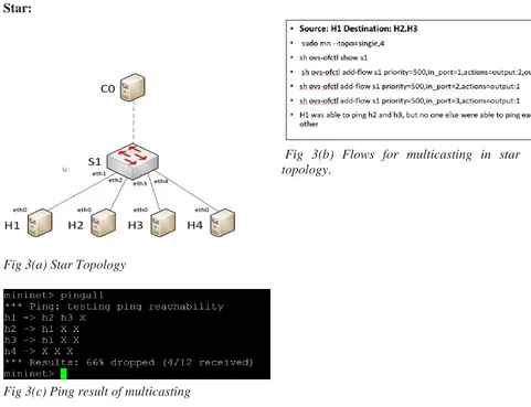
Star:
Fig 3(b) Flows for multicasting in star topology.
Fig 3(a) Star Topology
Fig 3(c) Ping result of multicasting
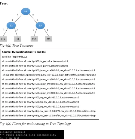
[image:12.612.69.550.72.441.2]Tree:
Fig 4(a) Tree Topology
Fig 4(b) Flows for multicasting in Tree Topology
Fig 4(c) Ping result of multicasting
[image:13.612.74.523.68.530.2] [image:13.612.72.285.498.583.2]Ring:
Fig 5(a) Ring Topology
Fig 5(c) Flows for multicasting in Ring Topology
Fig 5(d) Ping result for multicasting
Fig 5(b) Ring Topology Python Code
[image:14.612.63.583.71.616.2]After enabling multicasting, delay was added in the links of switches which have VNF placed on themwhich was doneusing the TCLink class. The usage of TCLink can be seen in the code of the custom topology shown in Fig 6(a).
Fig 6(a). Custom tree topology
[image:15.612.74.340.132.659.2]For the tree topology shown in Fig 6(a), delay was added in the links of H2 and H3. The code for this topology is shown in Fig 6(b).
Fig6 (c) Ping delay without link delay
Fig6 (d) Ping delay with link delay
When delay in the links has not been added, i.e. in Fig 6(b), it can be seen that the delay when H2 or H3 is pinged from H1 with a count of 1, the delay is less than 1 millisecond. But when 5 millisecond delay is added in the links of H2 and H3, i.e. in Fig 6(c), the delay is around 11 milliseconds because the ping request and response traverse the S2-H2 link twice which makes the delay more than 5+5 i.e. 10 milliseconds. Same is the case when H1 pings H3.
The experiments were performed on some real-world topologies like NSFNET, Cost239, Arpanet and Random 12.
2.1. NSFNET Topology:
Fig 7(a). NSFNET topology
Fig 7(b). NSFNET topology as seen in
OpenDaylight Controller
Fig 7(c). Ping result of multicasting in NSFNET topology
[image:17.612.74.560.134.594.2]to enable multicasting and the result of ping can be seen in Fig 7(c). Two functions were considered in the network which are initially placed at S11 and S10 respectively. Row1 of Table 1 shows the ping delay for the three source destination pairs for this case.
The paths for this case are as follows: S1-S3: 1,8,7,5,6,10,9,14,11,4,2,3 S1-S5: 1,3,6,10,9,14,11,4,5 S1-S9: 1,2,4,11,12,13,6,10,9
The VNF on S11 was then duplicated on S3 and the VNF on S10 is duplicated on S8. The paths now became:
S1-S3: 1,8,7,5,6,3 S1-S5: 1,3,6,10,9,8,7,5 S1-S9: 1,2,3,6,5,7,8,9
The paths have become shorter therefore the delay has reduced which can be seen in the row2 of Table1.
Then function1 is duplicated on S6 and Function2 on S3. The packets will now follow the following path to reach their destinations.
S1-S3: 1,3 S1-S5: 1,3,2,4,5 S1-S9: 1,3,6,10,9
Since the paths have become even shorter, the delay has decreased more. The delays for this case can be seen in row 3 of Table1.
[image:18.612.74.530.429.519.2]But after this, if I duplicate the functions on more nodes, the paths do not become shorter, therefore the delay now becomes constant. Row4 of Table1 shows the delay when VNFs are duplicated on S13 and S14 respectively. We see for this case; the delay does not decrease like before. The overall trend can be seen in the Fig 7(d) which shows delay vs number of VNFs used in the network.
Fig 7(d). Delay vs number of VNFs graph for NSFNET network
2.2. Arpanet Topology:
Fig 8(a). Arpanet topology
Fig 8(b). Arpanet topology as seen in OpenDaylight Controller
[image:19.612.61.536.93.647.2] [image:19.612.72.306.552.677.2]
Fig 8(a) shows ARPANET network. Here, the source is H1 and destination set consists of H5, H9 and H16. The topology was created in Mininet and OpenDaylight controller was used for centralized control. Fig 8(b) shows how the topology looks in the OpenDaylight window. Flows were written to enable multicasting and the result of ping can be seen in Fig 8(c). Two functions were considered in the network which are initially placed at S6 (implemented by doubling the link delays). Row1 of Table 2 shows the ping delay for the three source destination pairs for this case in milliseconds.
The paths for this case are as follows: S1-S5: 1,2,4,6,7,5
S1-S9: 1,2,4,6,8,9
S1-S16: 1,2,4,6,8,20,19,16
The 2 VNFs are now implemented on S6 and S15. The paths are: S1-S5: 1,2,4,6,8,20,19,16,15,9,7,5
S1-S9: 1,2,4,6,8,20,19,16,15,9 S1-S16: 1,2,4,6,7,9,15,16
Row2 of Table2 shows the delay of pinging the multiple destinations from H1 for this case. The VNF on S6 is then duplicated on S11 and the VNF on S15 is duplicated on S8.
The paths now become: S1-S5: 1,11,10,8,6,7,5 S1-S9: 1,11,10,8,9 S1-S16: 1,11,12,13,15,16
The paths have become shorter therefore the delay has reduced which can be seen in row3 of Table2.
After duplicating the function1 on S3 and Function2 on S4, the paths are: S1-S5: 1,3,2,4,5
S1-S9: 1,11,10,8,9
S1-S16: 1, 11,12,13,15,16
Since the paths are shorter as compared to previous case for H5, the delay has decreased. But for H9 and H16, the paths are same, so the delay is almost same.
[image:20.612.92.535.582.690.2]But after this, if the functions are duplicated on more nodes, the paths remain the same, therefore the delay now becomes constant. Row4 of Table2 shows the delay when VNFs are duplicated on S2 and S20 respectively. We see for this case; the delay does not decrease like before. The overall trend can be seen in the Fig 8(d) which shows delay vs number of VNFs used in the network.
Fig 8(d). Delay vs number of VNFs graph for Arpanet topology
2.3. Cost239 Topology:
Fig 9(a). Cost239 topology
[image:21.612.114.458.77.210.2] [image:21.612.91.534.193.682.2]Fig 9(a) shows COST239 network. Here, the source is H1 and destination set consists of H3 and H5. The topology was created in Mininet and OpenDaylight controller was used for centralized control. Fig 9(b) shows how the topology looks in the OpenDaylight window. Flows were written to enable multicasting and the result of ping can be seen in Fig 9(c). Two functions were considered in the network which are initially placed at S6 (implemented by doubling the link delays). Row1 of Table 2 shows the ping delay for the three source destination pairs for this case in milliseconds.
The paths for this case are as follows: S1-S3: 1,8,6,7,3
S1-S5: 1,8,6,5
The 2 VNFs are now placed on S6 and S10. Row2 of Table3 shows the delay for this case. The paths that packets follow from source to destinations are:
S1-S3: 1,8,6,10,3 S1-S5: 1,8,6,10,5
The VNF on S6 is then duplicated on S8 and the VNF on S10 is duplicated on S5. The paths now become:
S1-S3: 1,8,6,5,3 S1-S5: 1,8,6,5
The paths have become shorter therefore the delay has reduced which can be seen in the row3 of Table3.
After duplicating the function1 on S4 and Function2 on S11, the paths are: H1-H3: 1,4,5,3
H1-H5: 1,4,5
[image:22.612.91.430.502.607.2]Since the paths have a little shorter as compared to previous case, the delay is only a little less. But after this, if the functions are duplicated on more nodes, the paths remain the same, therefore the delay now becomes constant. Row4 of Table3 shows the delay when VNFs are duplicated on S9 and S7 respectively. We see for this case; the delay does not decrease like before. The overall trend can be seen in the Fig 9(d) which shows delay vs number of VNFs used in the network.
Fig 9(d). Delay vs number of VNFs graph for Cost239 topology
2.4. Random12 Topology:
[image:23.612.111.540.78.212.2] [image:23.612.114.490.307.492.2]Fig 10(b). Ranom12 topology as seen in OpenDaylight Controller 10(c). Ping result of multicasting in Ranom12 Topology
Fig 10(a) shows RANDOM12 network. Here, the source is H1 and destination set consists of H3, H5 and H9. The topology was created in Mininet and OpenDaylight controller was used for centralized control. Fig 10(b) shows how the topology looks in the OpenDaylight window. Flows were written to enable multicasting and the result of ping can be seen in Fig 10(c). Two functions were considered in the network which are initially placed at S8 (implemented by doubling the link delays). Row1 of Table4 shows the ping delay for the three source destination pairs for this case in milliseconds.
The paths for this case are as follows: S1-S3: 1,12,9,8,6,5,3
S1-S5: 1,12,9,8,6,5 S1-S9: 1,2,7,8,9
The 2 VNFs are now placed on S8 and S2. Row2 of Table4 shows the delay for this case. The paths that packets follow from source to destinations are:
S1-S3: 1,12,9,8,7,2,3 S1-S5: 1,2,7,8,6,5 S1-S9: 1,2,7,8,9
The VNF on S8 is then duplicated on S12 and the VNF on S2 is duplicated on S6. The paths now become:
S1-S3: 1,12,11,2,3 S1-S5: 1,2,7,8,6,5 S1-S9: 1,2,7,8,9
The paths have become shorter for H3, therefore the delay has reduced which can be seen in the row3 of Table4.
[image:24.612.90.558.64.325.2]S1-S3: 1,2,3 S1-S5: 1,2,3,5 S1-S9: 1,12,11,9
[image:25.612.89.542.210.310.2]Since the paths have a little shorter as compared to previous case, the delay is only a little less. But after this, if the functions are duplicated on more nodes, the paths remain the same, therefore the delay now becomes constant. Row4 of Table4 shows the delay when VNFs are duplicated on S5 and S8 respectively. We see for this case; the delay does not decrease like before. The overall trend can be seen in the Fig 10(d) which shows delay vs number of VNFs used in the network.
Table 4. Delay for different placements of VNFs in the Ranom12 topology
[image:25.612.101.541.346.469.2]CONCLUSION
This project addresses the trade-off between cost of VNFs in the network and the delay of
communication between the source and destination in a multicast NFV environment. The
experiments were performed on four real world topologies simulated in Mininet tool. The
VNFs were duplicated on different switches in the network and the corresponding source
destination ping delay was observed. The trend of cost vs delay was noticed. For all the
topologies, a trade-off was observed. As the number of VNFs increased, the delay between the
source and destinations decreases up to a certain number of VNFs and after that the delay does not
REFERENCES
1. S. Q. Zhang, A. Tizghadam, B. Park, H. Bannazadeh and A. Leon-Garcia, "Joint NFV placement and routing for multicast service on SDN," NOMS 2016 - 2016 IEEE/IFIP Network Operations and Management
Symposium, Istanbul, 2016, pp. 333-341. doi: 10.1109/NOMS.2016.7502829
2. S. Q. Zhang, Q. Zhang, H. Bannazadeh and A. Leon-Garcia, "Network Function Virtualization enabled multicast routing on SDN," 2015 IEEE International Conference on Communications (ICC), London, 2015, pp. 5595-5601.
doi: 10.1109/ICC.2015.7249214
3. H. Mekky, F. Hao, S. Mukherjee, T. V. Lakshman and Z. L. Zhang, "Network function virtualization enablement within SDN data plane," IEEE INFOCOM 2017 - IEEE Conference on Computer Communications, Atlanta, GA, 2017, pp. 1-9.
doi: 10.1109/INFOCOM.2017.8057138
4. R. Zhu, D. Niu, B. Li and Z. Li, "Optimal multicast in virtualized datacenter networks with software switches," IEEE INFOCOM 2017 - IEEE Conference on Computer Communications, Atlanta, GA, 2017, pp. 1-9.
doi: 10.1109/INFOCOM.2017.8057081
5. W. Ma, O. Sandoval, J. Beltran, D. Pan and N. Pissinou, "Traffic aware placement of interdependent NFV middleboxes," IEEE INFOCOM 2017 - IEEE Conference on Computer Communications, Atlanta, GA, 2017, pp. 1-9.
doi: 10.1109/INFOCOM.2017.8056993
6. H. Feng, J. Llorca, A. M. Tulino, D. Raz and A. F. Molisch, "Approximation algorithms for the NFV service distribution problem," IEEE INFOCOM 2017 - IEEE Conference on Computer Communications, Atlanta, GA, 2017, pp. 1-9.
doi: 10.1109/INFOCOM.2017.8057039
7. M. A. Saleh and A. E. Kamal, "Many-to-Many Traffic Grooming in WDM Networks," in IEEE/OSA Journal of Optical Communications and Networking, vol. 1, no. 5, pp. 376-391, Oct. 2009.
doi: 10.1364/JOCN.1.000376
8. Prithviraj Patil, Akram Hakiri, Shashank Shekhar, Aniruddha Gokhale. Scalable and Adaptive Software Defined Network Management for Cloud-hosted Group Communication Applications. 10th IEEE/ACM International Conference on Utility and Cloud Computing UCC 2017, Dec 2017, Austin, United States. 2017, 〈10.1145/3147213.3147220〉. 〈hal-01633339〉
9. M. A. Saleh and A. E. Kamal, "Design and Provisioning of WDM Networks With Many-to-Many Traffic Grooming," in IEEE/ACM Transactions on Networking, vol. 18, no. 6, pp. 1869-1882, Dec. 2010.
doi: 10.1109/TNET.2010.2051234
10. M. S. Yoon and A. E. Kamal, "NFV Resource Allocation Using Mixed Queuing Network Model," 2016 IEEE Global Communications Conference (GLOBECOM), Washington, DC, 2016, pp. 1-6.
doi: 10.1109/GLOCOM.2016.7842023
11. Pooja. And Manu Sood. SDN and Mininet:Some Basic Concepts. Volume: 07 Issue: 02 Pages: 2690-2693 (2015) ISSN: 0975-0290. 2690