Adv. Radio Sci., 6, 259–264, 2008 www.adv-radio-sci.net/6/259/2008/
© Author(s) 2008. This work is distributed under the Creative Commons Attribution 3.0 License.
Advances in
Radio Science
Hardware Accelerators for Elliptic Curve Cryptography
C. Puttmann1, J. Shokrollahi2, M. Porrmann1, and U. R ¨uckert1
1Heinz Nixdorf Institute, University of Paderborn, Germany 2Chair for System Security, Ruhr-University of Bochum, Germany
Abstract. In this paper we explore different hardware accel-erators for cryptography based on elliptic curves. Further-more, we present a hierarchical multiprocessor system-on-chip (MPSoC) platform that can be used for fast integration and evaluation of novel hardware accelerators. In respect of two application scenarios the hardware accelerators are coupled at different hierarchy levels of the MPSoC platform. The whole system is implemented in a state of the art 65 nm standard cell technology. Moreover, an FPGA-based rapid prototyping system for fast system verification is presented. Finally, a metric to analyze the resource efficiency by means of chip area, execution time and energy consumption is in-troduced.
1 Introduction
Data security is an important requirement for many appli-cations in our daily life. Especially internet applications such as e-commerce need to transmit secret data via inse-cure communication channels. Therefore, various crypto-graphical methods exist that allow to protect sensitive data. Asymmetric cryptography, which is also known as public-key cryptography, does not only provide algorithms for en-cryption and deen-cryption of data, but also for digital signa-tures and authentication. Recently asymmetric cryptography based on elliptic curves is gaining interest. Compared to traditional asymmetric techniques, e.g. the RSA algorithm, the elliptic curve cryptography (ECC) achieves an equivalent level of security with smaller key sizes. Using elliptic curve cryptography therefore results in memory as well as band-width savings.
Nevertheless, computational intensive operations emerge during the processing of ECC protocols. The scalar multipli-cation on elliptic curves represents a frequently required and complex operation. The acceleration of this task by dedicated hardware units can not only speed up the execution time, but
Correspondence to: C. Puttmann
also help to save energy. In this paper, we propose different types of hardware accelerators for scalar multiplication in re-spect of two application scenarios. On one hand, we consider mobile devices with limited power resources such as smart-cards. On the other hand, security servers are considered, where high performance is more important than power con-sumption and costs in terms of chip area.
Our work presents various hardware accelerators for ellip-tic curve cryptography, which are evaluated by integration into a multiprocessor system-on-chip (MPSoC). This pro-posed evaluation platform is scalable and can be adapted to suit different application scenarios. Dedicated hardware blocks can easily be integrated at different hierarchy levels of the MPSoC, which allows a comfortable evaluation of novel accelerators. Furthermore, the whole system is mapped onto an FPGA-based rapid prototyping environment in order to speed up simulation and verification.
The proposed hardware accelerators are synthesized in a modern 65 nm standard cell technology and analyzed regard-ing their resource efficiency in terms of chip area, execution speed and power consumption. Furthermore, a metric is in-troduced to compare the resource efficiency of different im-plementations in respect of the considered application sce-nario.
The paper is structured as follows. Section 2 gives a brief overview of the mathematical background of elliptic curve cryptography. In Sect. 3 the evaluation platform that is used to integrate and verify the hardware accelerators is discussed. The proposed hardware accelerators as well as the metric for analyzing their resource efficiency are explained in detail in Section 4. Finally, Sect. 5 concludes the paper.
2 Elliptic Curve Arithmetic
In this section the elliptic curve cryptography based on bi-nary field arithmetic is introduced. The general equation for a non-supersingular elliptic curve E over the binary finite fieldF2mis given by equation:
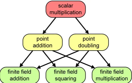
finite field addition finite field squaring finite field multiplication point addition point doubling scalar multiplication
Fig. 1. Arithmetic hierarchy of elliptic curve cryptography.
for appropriate parameters a, b∈F2m. The set of points
(x, y)∈F2m×F2m, which satisfy Eq. (1), together with the identity elementO, generate an additive abelian group. Let
P=(xp, yp) and Q=(xq, yq) be two given points on the curve in Eq. (1). The point addition P+Q as well as the point doublingP+Pare two operations defined on the ellip-tic curveE, which can geometrically be represented by the tangent and chord operation, respectively. By applying the point addition and point doubling operations, we are able to multiply an integerk with a pointP, which is the result of
k−1 times adding the pointP to itself. This operation is known as scalar or point multiplicationk×P. Figure 1 de-picts this hierarchical structure of arithmetic operations used for elliptic curve cryptography over finite fields.
2.1 Projective Coordinates
Naturally, point addition and point doubling also require a field inversion when using affine coordinates(x, y). Since inversion is a very expensive operation compared to mul-tiplication, addition and squaring in finite fields, we use projective coordinates. In standard projective coordinates the points on the elliptic curve are represented as a triple
(X, Y, Z)in such a way thatx→X/Zandy→Y /Z. By us-ing projective coordinates only one finite field inversion is required at the end of a scalar multiplication in order to trans-form the projective coordinates back to affine coordinates. 2.2 Montgomery Ladder Algorithm
In Montgomery (1987) a very efficient method to perform the scalar multiplication is presented, which was applied to elliptic curve cryptography by L´opez and Dahab (1999). The method is known as montgomery ladder and is shown at point level in Algorithm 1. Since in every loop iteration the same operations are performed, namely one point addition and one point doubling, the montgomery ladder algorithm is shielded against timing attacks and simple power analysis attacks.
2 Elliptic Curve Arithmetic
In this section the elliptic curve cryptography based on bi-nary field arithmetic is introduced. The general equation for a non-supersingular elliptic curveE over the binary finite fieldF2m is given by equation:
E:y2
+xy=x3
+ax2
+b (1)
for appropriate parametersa, b ∈ F2m. The set of points
(x, y) ∈ F2m ×F2m, which satisfy (1), together with the
identity elementO, generate an additive abelian group. Let
P = (xp, yp)andQ = (xq, yq)be two given points on the curve in (1). The point additionP +Qas well as the point doublingP +P are two operations defined on the elliptic curveE, which can geometrically be represented by the tan-gent and chord operation, respectively. By applying the point addition and point doubling operations, we are able to multi-ply an integerkwith a pointP, which is the result ofk−1
times adding the pointPto itself. This operation is known as scalar or point multiplicationk· P. Figure 1 depicts this hi-erarchical structure of arithmetic operations used for elliptic curve cryptography over finite fields.
2.1 Projective Coordinates
Naturally, point addition and point doubling also require a field inversion when using affine coordinates(x, y). Since in-version is a very expensive operation compared to multiplica-tion, addition and squaring in finite fields, we use projective coordinates. In standard projective coordinates the points on the elliptic curve are represented as a triple(X, Y, Z)in such a way thatx→X/Zandy→Y /Z. By using projective co-ordinates only one finite field inversion is required at the end of a scalar multiplication in order to transform the projective coordinates back to affine coordinates.
finite field
addition finite fieldsquaring multiplicationfinite field point
addition doublingpoint scalar
multiplication
Fig. 1. Arithmetic hierarchy of elliptic curve cryptography.
Algorithm 1 The Montgomery ladder algorithm for scalar multiplication expressed at point level.
Input: A pointPon the elliptic curveE, together with the binary representation of the scalarkas(ki−1ki−2. . . k1k0)2.
Output: k· P
P1← P,P2←2P
forjfromi−2downto0do ifkj= 1then
P1← P1+P2,P2←2P2
else
P2← P1+P2,P1←2P1
end if end for
2.2 Montgomery Ladder Algorithm
In Montgomery (1987) a very efficient method to perform the scalar multiplication is presented, which was applied to elliptic curve cryptography by L´opez and Dahab (1999). The method is known as montgomery ladder and is shown at point level in Algorithm 1. Since in every loop iteration the same operations are performed, namely one point addition and one point doubling, the montgomery ladder algorithm is shielded against timing attacks and simple power analysis attacks. 2.3 Polynomial Basis Representation
As illustrated in Figure 1, finite field arithmetic represents the base operations. Therefore, an efficient representation of the finite field elements inF2mis important. The polynomial
basis representation can be described as a vector space of di-mensionmover the fieldF2and is one of the most common representations in ECC. Field elements in polynomial basis representation are expressed as binary polynomials of degree m−1as follows:
a(x) =
mX−1
i=0
ai·xi with ai∈ {0,1} (2)
One benefit of binary fields is that the finite field addition is calculated by a carry-free XOR operation of corresponding coefficients. Finite field squaring can be achieved by shifting each bitaitoa2iand filling the gaps with zeros. Similar to finite field multiplication, the result is a binary polynomial of degree2m−2, which has to be reduced modulo an irre-ducible, sparse polynomial of degreem. However, the finite field multiplication is equivalent to the product of the corre-sponding polynomials, which is, compared to addition and squaring, the most computational intensive operation. 2.4 Karatsuba Multiplication Method
In order to reduce the complexity of polynomial multipli-cation, the method of Karatsuba and Ofman (1963) is ap-plied. Whereas “classically” the coefficients of the product
(a1x+a0)(b1x+b0) = a1b1x 2
+ (a1b0⊕a0b1)x+a0b0 2.3 Polynomial Basis Representation
As illustrated in Fig. 1, finite field arithmetic represents the base operations. Therefore, an efficient representation of the finite field elements in F2m is important. The polynomial basis representation can be described as a vector space of dimensionmover the fieldF2and is one of the most common
representations in ECC. Field elements in polynomial basis representation are expressed as binary polynomials of degree
m−1 as follows:
a(x)=
m−1 X
i=0
ai×xi with ai ∈ {0,1} (2)
One benefit of binary fields is that the finite field addition is calculated by a carry-free XOR operation of corresponding coefficients. Finite field squaring can be achieved by shifting each bitai toa2i and filling the gaps with zeros. Similar to finite field multiplication, the result is a binary polynomial of degree 2m−2, which has to be reduced modulo an irre-ducible, sparse polynomial of degreem. However, the finite field multiplication is equivalent to the product of the corre-sponding polynomials, which is, compared to addition and squaring, the most computational intensive operation. 2.4 Karatsuba Multiplication Method
In order to reduce the complexity of polynomial mul-tiplication, the method of Karatsuba and Ofman (1963) is applied. Whereas “classically” the coefficients of the product(a1x+a0)(b1x+b0)=a1b1x2+(a1b0⊕a0b1)x+a0b0
from the four input coefficientsa1,a0,b1, andb0are
com-puted with 4 multiplications and 1 addition, the Karatsuba formula uses only 3 multiplications and 4 additions in binary fields:
(a1x+a0)(b1x+b0)= (3)
a1b1x2+((a1⊕a0)(b1⊕b0)⊕a1b1⊕a0b0)x+a0b0.
C. Puttmann et al.: Hardware Accelerators for ECC 261
ALU bus
controller
PC address calculation
decoder priority
decoder FETCH
EXECUTE DECODE
address
A B
X Y
result imm./const.
address offsets
opcodes PC reg. addresses address offsets opcodes
reg. I/O
access error
IRQs
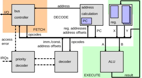
Fig. 2. N-Core processor architecture providing a three-stage pipeline.
saved multiplications and an asymptotical cost ofO(m1.59)
compared to the classical cost ofO(m2)is achieved (Han-kerson et al., 2004).
3 Evaluation Platform
In Niemann et al. (2007) we presented the development of a scalable and hierarchical multiprocessor system-on-chip (MPSoC) architecture. This system architecture is used here as an evaluation platform for the integration of hardware ac-celerators.
3.1 N-Core Processor Element
The core processing element is our 32-bit RISC microproces-sor named N-Core (Niemann et al., 2007). The N-Core com-prises a common load-store architecture that is depicted in Fig. 2. The processor provides a three-stage pipeline, which performs instruction fetch, decode and execute. Two inde-pendent banks of sixteen 32-bit registers allow fast program context switching, e.g. for fast interrupt handling. Although the N-Core provides a 32-bit data bus, instructions have a fixed width of 16 bit, which delivers a high code density. Due to 11% free opcode space, instruction set extensions can be added to the microprocessor.
3.2 Hierarchical MPSoC Architecture
The processor core is extended with local data and instruc-tion memory, a programmable interrupt controller (PIC) and a timer module to form a N-Core subsystem. The N-Core subsystem represents the lowest level of hierarchy within the MPSoC system. At the next higher level, a parametrizable amount of N-Core subsystems are connected via an on-chip Wishbone bus. Together with a shared memory this multicessor arrangement forms a cluster. At cluster level the pro-cessor elements can send messages directly to each other via the Wishbone bus as well as exchange data via the common shared memory. In this way, applications can be parallelized
switch box
cluster and shared memory
N-Core subsystem with local memory
crypto accelerator wishbone on-chip bus network-on-chip
Fig. 3. Integration of hardware accelerators at different levels of our
MPSoC-based evaluation platform.
and processed cooperatively by the N-Core subsystems. At the top level of hierarchy, several clusters are connected through switch boxes over the network-on-chip (NoC). The NoC communication structure is described in Puttmann et al. (2007) and features packet-switched wormhole routing with up to 42 GBit/s data throughput.
3.3 Coupling of Hardware Accelerators
Depending on the requirements of the application scenario, hardware accelerators can be coupled at different levels of hi-erarchy, resulting in several resource utilization variants. As depicted in the top right cluster of Fig. 3, hardware accelera-tors in terms of instruction set extensions can be added to the N-Core subsystem. This integration means a very close cou-pling to the processor with little hardware overhead. In the bottom right cluster of Fig. 3, the accelerator is connected to the local on-chip bus of the cluster. In this way, each proces-sor of the corresponding cluster can access the hardware ac-celerator. Moreover, the direct coupling to a switch box (see bottom left cluster in Fig. 3) results in high data throughput due to the close connection to the network-on-chip. Here, every processor of the whole system can access the hardware accelerator. In order to easily integrate the same hardware unit at different levels, we developed wrapper modules that automatically provide an interface for the desired coupling (Niemann et al., 2007).
3.4 Rapid Prototyping Environment
Fig. 4. Fast emulation of new hardware accelerators by using our FPGA-based rapid prototyping system RAPTOR2000.
Table 1. Synthesis results for a 65 nm standard cell technology and
a Xilinx Virtex-II FPGA implementation, respectively.
area power
[mm²] [mW] [slices] [RAM16]
N-Core processor 0.078 17.20 3206 0
N-Core subsystem1
0.613 45.16 3662 16
Cluster2
3.443 357.14 15362 80
Switch box 0.449 315.12 14133 0
ASIC FPGA
utilization
1
N-Core processor, 32 KB local memory, interrupt controller, timer module
2
4 N-Core subsystems, 32 KB shared memory, on-chip wishbone bus
motherboard, which can be equipped with up to six appli-cation specific daughterboard modules. Based on FPGA daughterboard modules, RAPTOR2000 is able to emulate circuits with a complexity of more than 200 million transis-tor gates. The host computer can communicate via a PCI bus interface with the RAPTOR2000 board and each attached daughterboard, respectively. Additionally, we have devel-oped daughterboard modules that provide various commu-nication standards. For example, an ethernet daughterboard can be used to stimulate the design under test with real world network traffic.
The implementation result of the MPSoC core compo-nents are shown in Table 1. We mapped the system to a 65 nm technology for ASIC fabrication as well as to a Xilinx XC2V8000-4 FPGA for rapid prototyping. The ASIC imple-mentation is based on a low power (regular threshold volt-age) standard cell library under typical operating conditions. The N-Core subsystem runs at a frequency of 400 MHz, which is also the operating frequency of a cluster. How-ever, the network-on-chip as well as the switch box achieves a maximum clock frequency of 718 MHz. Each XC2V8000-4 FPGA can host one cluster including XC2V8000-4 N-Core subsystems and a switch box, which runs at 12.5 MHz. The system can be easily scaled by using more than one FPGA daughter-board (Niemann et al., 2007).
MULTIPLY SQUARE ADD
..
.
... ... ... ... ...
...
REG. FILE m
m
m
m
m
clk
rst
run
k_in x_in
y_in
valid
x_out y_out
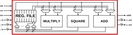
Fig. 5. Architecture of the high performance hardware accelerator
for scalar multiplication.
4 Hardware Accelerators
In this section, various hardware accelerators for elliptic curve cryptography are presented. As explained in Sect. 2, we concentrate on the scalar multiplication in binary fields. Throughout the rest of this paper, we refer to the binary field F2233, which is one of the recommended extension fields by
the National Institute of Standards and Technology (2000). The hierarchy level for integration into the evaluation plat-form is chosen in respect to the application scenario. Fur-thermore, a metic for analyzing the resource efficiency is proposed and exemplarily applied to select the best hardware accelerator for a given application scenario.
4.1 High Performance Scenario
High performance hardware accelerators are required for systems such as internet servers, which have to handle many secure data transactions at one time, e.g. for online-banking applications. Fast computation and high data throughput are more important in this application scenario than power con-sumption and costs in terms of chip area.
C. Puttmann et al.: Hardware Accelerators for ECC 263
Table 2. Resource utilization for 65 nm standard cell technology at
200 MHz clock frequency and typical operating conditions.
absolute relative absolute relative absolute relative
[μm²] [%] [mW] [%] [ms] [%]
N-Core 57190 0.00 9.23 0.00 57.59 0.00
N-Core (ISE1) 57519 0.58 9.49 2.82 50.92 -11.58
N-Core (ISE2) 59290 3.67 7.35 -20.37 26.42 -54.12
N-Core (ISE3) 64734 13.19 12.00 30.01 20.19 -64.94
chip area power consumption execution time
based on the Karatsuba method requires 3 clock cycles in a pipelined fashion. Furthermore, the register file can store 7 finite field elements, which is sufficient for calculating the scalar multiplication. Due to the generic architecture, the hardware accelerator can easily be adapted to different field sizes. The scalar multiplication is calculated using the mont-gomery ladder algorithm as explained in Sect. 2. Moreover, the hardware accelerator handles coordinate transformation, i.e. affine coordinates are supported as input and output for-mat, while internally projective coordinates are used for cal-culation.
The proposed hardware accelerator is coupled to a switch box port at the highest hierarchy level of the evaluation plat-form (cf. Fig. 3) for several reasons. At this level, the highest data throughput is achieved due to the close coupling to the network-on-chip. Furthermore, the hardware accelerator can operate autonomously without the need for an attached mi-croprocessor.
Again, the hardware accelerator was synthesized using a 65 nm standard cell technology with typical operating condi-tions. A total chip area of 0.279 mm2is required to support the binary fieldF2233. The hardware accelerator achieves a
clock frequency of 625 MHz, i.e. the complete scalar mul-tiplication is calculated in 7.2µs and consumes 72.8 mW power. Respectively, 15365 slices are needed on a Xilinx XC2V8000-4 FPGA, which runs with 50 MHz clock fre-quency, resulting in 90µs calculation time.
4.2 Low Power Scenario
In contrast to the high performance scenario, we now con-sider low power devices like smartcards. These are com-monly used in mobile devices with limited energy resources and restricted chip area. Instead of high performance, the motivation for hardware accelerators here is to save energy with little increase of chip area. In order to reach this aim, we analyzed several types of instruction set extensions (ISE). Regarding the evaluation platform, instruction set extensions are directly implemented to the N-Core processor and hence coupled at the lowest hierarchy level. For a smartcard sce-nario, the evaluation platform is scaled down to a minimum of only one single N-Core comprising instruction set exten-sions.
98,62 74,85
1,74 1,00
23,50
41,59 1,49
1,00
5,53 5,76 1,24 1,00
0 10 20 30 40 50 60 70 80 90 100 N-Core
(ISE3) N-Core (ISE2) N-Core (ISE1) N-Core
normal (α=-1, β=-1, γ=-1) power (α=-1, β=-3, γ=-2)
speed (α=-3, β=-2, γ=-1)
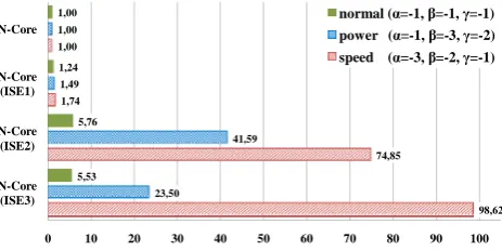
Fig. 6. Resource efficiency of different types of instruction set
ex-tensions.
In Puttmann et al. (2008), we present a two-stage frame-work for automatic instruction set extension. As a result, we implemented three different instruction set extensions. The first type of ISE combines already existing instructions, which are frequently used, to new super instructions. The analysis of the scalar multiplication showed that the instruc-tion set of the N-Core processor can benefit from combi-nations of shift and xor. Therefore, we added three super instructions to the N-Core, namely LSRIxor, LSLIxor andLSRIandadd. This modification is in the following referred to as ISE1. Whereas ISE1 only combines existing instructions to new super instructions, the second type of in-struction set extension (referred to as ISE2) introduces a new instruction, calledMULGF2. This instruction multiplies two 32-bit binary field polynomials by using existing functions of the arithmetic logical unit (ALU). Multiplication with ISE2 is realized bit by bit utilizing the existing shift unit and xor function of the ALU. The third type of instruction set ex-tension (ISE3) also supports thisMULGF2instruction, but a dedicated hardware unit for binary field multiplication is im-plemented instead of using existing ALU functions.
Table 2 shows the absolute resource utilization as well as the relative changes compared to an original N-Core proces-sor. The synthesis results are based on high threshold voltage standard cells, since we are considering a low power sce-nario. Therefore, the clock frequency of the N-Core is re-duced to 200 MHz and only a chip area of 0.057 mm2is re-quired. The execution time in Table 2 refers again to a scalar multiplication inF2233.
4.3 Resource Efficiency
In order to select the best hardware accelerator for a given application scenario, a metric for resource efficiency is in-troduced in this section. The resource efficiency of the three variants of instruction set extensions is exemplarily analyzed. Therefore, we define resource efficiency (RE) as
RE=Tα×Eβ ×Aγ (4)
with execution time (T), energy consumption (E) and chip
exponent (α,β,γ) to characterize the focus of the considered application scenario.
Figure 6 shows the resource efficiency of the three ISE variants (cf. Table 2), which are normalized to the resource efficiency of the original N-Core processor. We character-ized three resource weightings, namely normal, power and
speed. The exponentsα,β andγ are all negative, so that a better utilization of any resource results in a better resource efficiency. The solid bars depict the resource efficiency with each component equally weighted, i.e. chip area, energy con-sumption and execution time are of the same importance. However, for the smartcard application scenario, we focus on low power implementations with little hardware overhead. Therefore, the checkered bars depict the resource efficiency, where energy consumption (β= −3) is more important than chip area (γ= −2), which in turn is more important than ex-ecution time (α= −1). Therefore, ISE2 would be the best suited implementation for this application scenario, since it achieves the highest resource efficiency with emphasis on power. In contrast, the striped bars show the resource effi-ciency when focusing on speed. Consequently, the execution time (α= −3) is here more important than the energy con-sumption (β= −2), which again is more important than the chip area (γ= −1). In this case, ISE3 represents the best suited hardware accelerator, because it achieves the highest resource efficiency with respect to execution speed.
5 Conclusions
In this paper we have presented various hardware accelera-tors for cryptography based on elliptic curves. The proposed scalable multiprocessor system-on-chip evaluation platform allows an easy integration of hardware accelerators at differ-ent levels of hierarchy. In order to speed up the verification of novel hardware accelerators, the evaluation system can be emulated by using our FPGA-based rapid prototyping envi-ronment RAPTOR2000. A high performance hardware ac-celerator was developed, which calculates a scalar multipli-cation inF2233in 7.2µs. Moreover, different types of
instruc-tion set extensions were introduced that provide energy sav-ings up to 63%. Finally, a metric for analyzing the resource efficiency was defined, which helps to select the best suitable hardware accelerator for a given application scenario.
Acknowledgements. The research described in this paper was funded in part by the Federal Ministry of Education and Research (Bundesministerium f¨ur Bildung und Forschung – BMBF), regis-tered there under grant number 01AK065F (NGN-PlaNetS), and by the German Research Foundation (Deutsche Forschungsgemein-schaft – DFG) under project RU 477/8.
References
Hankerson, D., Menezes, A. J., and Vanstone, S. A.: Guide to Elliptic Curve Cryptography, Springer Professional Computing, Springer, Berlin, 2004.
Kalte, H., Porrmann, M., and R¨uckert, U.: A Prototyping Plat-form for Dynamically Reconfigurable System-on-Chip Designs, in: Proceedings of the IEEE Workshop Heterogeneous reconfig-urable Systems-on-Chip (SoC), Hamburg, Germany, http://www. raptor2000.de, 2002.
Karatsuba, A. A. and Ofman, Y.: Multiplication of Multidigit Num-bers on Automata, Soviet Physics Doklady, 7, 595-596, 1963. L´opez, J. and Dahab, R.: FastMultiplication on Elliptic Curves over
GF(2m) without Precomputation, in: CHES 99: Proceedings of the First InternationalWorkshop on Cryptographic Hardware and Embedded Systems, Springer-Verlag, London, UK, 316-327, 1999.
Montgomery, P. L.: Speeding the Pollard and Elliptic Curve Meth-ods of Factorization, Math. Comput., 48, 243-264, 1987. National Institute of Standards and Technology (NIST): Digital
Sig-nature Standard (DSS), U.S. Department Of Commerce, chap. Recommended Elliptic Curves for Federal Government Use, FIPS 186-2, 24-48, 2000.
Niemann, J.-C., Puttmann, C., Porrmann, M., and R¨uckert, U.: Resource Efficiency of the GigaNetIC Chip Multiprocessor Ar-chitecture, J. Syst. Architect., special issue on Architectural premises for pervasive computing, 53, 285-299, 2007.
Puttmann, C., Niemann, J.-C., Porrmann, M., and R¨uckert, U.: GigaNoC - A Hierarchical Network-on-Chip for Scalable Chip-Multiprocessors, in: Proceedings of the 10th EUROMICRO Conference on Digital System Design (DSD), 29–31 August, L¨ubeck, Germany, IEEE Computer Society, 495–502, 2007. Puttmann, C., Shokrollahi, J., and Porrmann, M.: Resource