Abstract
As the number of codewords adopted in phase-coding fringes increases, the solution of fringe orders leads to many mistakes. Consequently, errors of the unwrapped phase occur. Thus, increasing the codeword approach in a phase-coding fringe remains a challenge. In this paper, a modified stair phase-coding fringe is designed, and a new phase unwrapping algorithm based on shifting fringe order is presented. The main idea of this method is that the width ratio between the sinusoidal fringe and each stair phase of phase-coding fringe is set to 1: n. The fringe order retrieved from the phase-coding fringe can be multiplied by the shift itself, thereby assisting phase
unwrapping. This method adopts fewer codewords to replace the usual large number. As such, the approach gains two merits. One is that it guarantees a high measurement accuracy. The other is that it allows the measurement of isolated objects with complicated shapes. The experiments demonstrate that the proposed method is simple but effective.
Keywords:Phase-coding fringe, Phase measuring profilometry, Phase unwrapping, Phase-shifting
Background
With the rapidly development of computer technol-ogy, optical and optoelectronic technoltechnol-ogy,
three-dimensional measurement theory and technology
based on structured light has been rapid developed. Many methods have been proposed to recover 3D surface geometry using different principles [1]. Those methods characterized by non-contact operation, full-field acquisition and fast data processing has been widely used in industrial inspection, quality control, reverse engineer-ing, micro-fabrication and other fields [2–6].
Many methods have been utilized to measure com-plex surfaces. Zhao et al. [7] used two phase images with different precision in unwrapping. Considering the numerous images required in Zhao’s method, Li et al. [8] proposed two-frequency grating profilometry, which entails only one grating instead of changing gratings with different equivalent wavelengths. Zhang et al. [9] presented a phase unwrapping algorithm based on multi-frequency fringe projection. The method of combined fringes is also used in 3D meas-urement. Zhang et al. [10] suggested a method that
embeds a speckle-like signal in three sinusoidal fringe patterns to eliminate phase ambiguity. Basing from this technique, Feng et al. [11] proposed a novel speckle-embedded fringe projection method using a graphics processing unit to process data in real time. The Gray code plus phase-shifting method determines the codewords from image intensity [12–14]. However, the measurement resolution is limited by the errors derived from gray-level quantization and noise. Meanwhile, the codewords are less robust for measuring high-contrast surfaces and limited to 2m (where m is regarded as the number of Gray code patterns). Liu et al. [15] developed a novel encoded-phase technique for phase measuring profilometry, in which the differentially wrapped phases are regarded as codewords. This method is suitable for capturing dynamic scenes, but it is influenced by object texture and noise. Wang et al. [16] presented a novel absolute phase recovery technique with a phase-coding fringe. This technique not only pro-duces more codewords but also receives more robust measurement results for different fringe image bright-ness levels compared with Gray code techniques. Fu et al. [17] followed Wang’s theory and measured a blade with a complex shape. However, the
measure-ment accuracy was reduced when numerous
* Correspondence:[email protected]
Key Laboratory of Nondestructive Testing (Ministry of Education), Nanchang Hangkong University, Nanchang 330063, China
codewords were adopted. Different from the method proposed by Wang, Zheng et al. [18] introduced a technique wherein two sets of phase-coding fringes are projected to address the difficulty in judging the fringe order. Basing from Zheng’s foundation, Zhou et al. [19] developed a color fringe coding method to hasten the measurement speed. However, this tech-nique was required to handle the color crosstalk. Chen [20] added a correction method to stabilize the phase-unwrapping algorithm. Meanwhile, Xu et al. [21] proposed an encoding strategy that increases the range of unique phase distribution to 10π. This method is capable of reconstructing holes, steps, and other complicated shapes.
We propose the use of phase shifting algorithms to codify the codewords, which could be used for unwrap-ping procedure. In general, we need to project two sets of fringes: the first one set consists of a sequence of si-nusoidal fringe patterns used to determine the profile of the object under test, and the second is a sequence of stair phase-coding fringes used for determining the fringe orders. Moreover, two issues must be clarified. First, basing from Zhou’s method [19] shown in Fig. 1a, we design a modified stair phase-coding fringe that exactly retrieves the codewords. Second, the width ratio between the sinusoidal fringe and each stair phase of phase-coding fringe is set to 1: n. To facilitate the narra-tive, we use n = 2 as an example (Fig. 1b). In specific, each stair codeword corresponds to two wrapped phases. The width of each stair phase can be doubled by shifting itself. Then, the width of each stair phase and wrapped phase can be equal, and phase unwrapping can be achieved.
The paper is organized as follows. Section Methods describes the principles of the proposed method. Sec-tion Experiments and Results presents the experiments and results. Section Discussion discusses how to gener-ate good measurement results. Finally, Section Conclu-sion provides the concluConclu-sion.
Methods
Measurement system
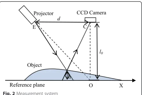
The measurement system based on triangulation is shown in Fig. 2. The optical center of the Digital Light Processing (DLP) and the Charge-Coupled-Device (CCD) camera are Point E and C, respect-ively. The optical axis of the projector and that of the CCD camera intersect at origin point O. The fringe is projected onto the measured object. The de-formed fringe pattern is captured by the CCD Fig. 1Two comparative methods: (a) Zhou’s method, and (b) proposed method
camera. The height of the measured object can be expressed as follows [22]:
h¼ l0Δϕ
2πf0dþΔϕ ð1Þ
Where l0 is the distance between the entrance
pupil of the CCD camera and the reference plane, and d is the distance between the entrance pupil of the CCD camera and the exit pupil of the projector. f0 is the spatial frequency of the sinusoidal fringe
pattern on the reference plane. Δϕ is the phase dif-ference between the corresponding point on the ob-ject and reference plane. The parameters l0, d and f0
are obtained by calibration. The verticality and paral-lel of the system are calibrated by the method of ref-erence [23].
Four-step phase-shifting algorithm
Phase-shifting method had been extensively adopted in optical metrology because of its measurement speed and accuracy. Over the years, a variety of phase-shifting algorithms have been developed, that include three-step, four-step, and lease-square algorithms [24]. Four-step phase-shifting algorithm can avoid the 1-th and 2-th non-linearity of the measurement system [25]. In consideration of the measurement speed and
accuracy, four-step phase-shifting algorithm is adopted in this paper.
In general, a four-step phase-shifting algorithm with equal phase shifts can be described as:
I1ðx;yÞ ¼A x;ð yÞ þB x;ð yÞcos½ϕðx;yÞ þπ ð2Þ
I2ðx;yÞ ¼A x;ð yÞ þB x;ð yÞcos½ϕðx;yÞ þ3π=2 ð3Þ
I3ðx;yÞ ¼A x;ð yÞ þB x;ð yÞcos½ϕðx;yÞ þ2π ð4Þ
I4ðx;yÞ ¼A x;ð yÞ þB x;ð yÞcos½ϕðx;yÞ þ5π=2 ð5Þ
Here, A(x,y) is the average intensity, B(x,y) is the in-tensity modulation and Φ(x,y) is the phase to be solved for. Simultaneously, solving Eqs. (2)-(5) leads to
Φðx;yÞ ¼ tan−1 I4ðx;yÞ−I2ðx;yÞ I1ðx;yÞ−I3ðx;yÞ
ð6Þ
The phase obtained in Eq. (6) ranges from −π to π with 2π discontinuities. A phase-unwrapping algorithm should be used to obtain continuous phase.
Algorithm of the designed stair phase-coding fringe
The following steps comprise the process of a modified stair phase-coding fringe.
Fig. 3One cross section of the stair phase
(1)Embed the codeword into the phaseφ′(x,y) with the following stair phase function:
φ′ðx;yÞ ¼‐πþfloor modðx‐1;pNÞ p
2π
N‐1 ð7Þ
where floor[x] is the largest integer not greater than x, mod(x,y) is the remainder after the division of x by y, p is the number of pixels per stair phase, and N is the step number in one rising stair phase. We define S = 1024/(p × N) as the sub-period number that corre-sponds to the segment number of φ′(x,y). In this sec-tion, p = 64, N = 4, and S = 4. The phase φ′(x,y) is
denoted as a red dash-and-dot line in Fig. 3.
(2)Normalize the phaseφ′(x,y) as follows:
φðx;yÞ ¼−3:13þ φ′ðx;yÞ−min φ′ðx;yÞ
maxðφ′ðx;yÞÞ−minðφ′ðx;yÞÞ
23:13
ð8Þ
where φ(x,y) is the coding phase ranging from−3.13 to 3.13, max(x) is the maximum value of x, and min(φ′) is the minimum value of φ′. The coding phase φ(x,y) is represented by a solid blue line in Fig.3.
(3)Put the coding phase into four-step phase-shifting fringe patterns:
Ic
kðx;yÞ ¼A xð ;yÞ þB xð ;yÞcos φðx;yÞ þðk−1Þ
π 2
h i
ð9Þ Fig. 5One cross section of coding phase and segmented fringe order
wherek= 1, 2, 3, 4. The phase-shifting fringeIc4is displayed in Fig.4.
New phase unwrapping algorithm
(1)Calculate coding phaseφ(x,y) with the phase-shifting algorithm:
φðx;yÞ ¼ tan−1 I
c 4−I
c 2 Ic
1−I c 3 !
ð10Þ
As shown in Fig.5, the blue line means one cross section of coding phaseφ(x,y).
(2)Quantize the decimal coding phaseφ(x,y) into the segmented integer fringe orderk00(x,y):
k00ðx;yÞ ¼ðN−1Þ φðx;yÞ−minðφðx;yÞÞ
maxðφðx;yÞÞ−minðφðx;yÞÞ
þ1
ð11Þ
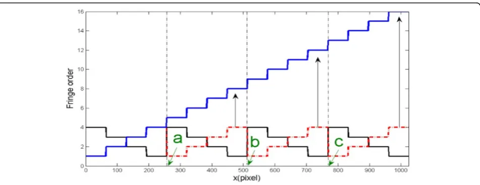
The segmented integer fringe orderk00(x,y) is represented by a red dash-and-dot line in Fig.5. (3)Generate a contrary fringe orderk01(x,y):
k01ðx;yÞ ¼Nþ1−k00ðx;yÞ ð12Þ
The contrary fringe orderk01(x,y) is denoted as a black line in Fig.6.
(4)Find the jump pixel point in the segmented fringe order as follows:
k01ðx;yÞ−k00ðx;yÞ ¼¼N−1 ð13Þ
Fig. 7One cross section of new fringe order
In Fig.6a, b, and c denote the jump pixel points in the pixel axis. When the two segmented fringe orders satisfy Eq. (13), the pixels are saved in the jump pixel points matrix [a,b,c]x× 3.
(5)Connect the segmented fringe order to a continuous fringe orderk1(x,y) as follows:
k1ðx;1:aÞ ¼k00ðx;1:aÞ
k1ðx;aþ1:bÞ ¼k00ðx;aþ1:bÞ þN1
k1ðx;bþ1:cÞ ¼k00ðx;bþ1:cÞ þN2
k1ðx;cþ1:sÞ ¼k00ðx;cþ1:sÞ þN3
8 > > < > >
: ð14Þ
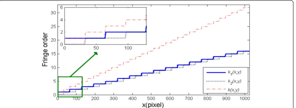
where s is the total pixels in each row, ands= 1024. (6)Create a new fringe order by the shift half frequency
ofk1as shown below:
k2ðx;yÞ ¼ k1ðx;yþp=2Þ; y>p=2
0 ; y≤p=2
ð15Þ
k xð ;yÞ ¼k1ðx;yÞ þk2ðx;yÞ ð16Þ
wherek2(x,y) is the shifted fringe order andk(x, y) is the new fringe order. Additional details are provided in the magnifying frame in Fig.7.
(7)Obtain the continue phaseΨ(x,y) as follows:
Ψðx;yÞ ¼2πk xð ;yÞ þΦðx;yÞ ð17Þ
In Fig. 8, the blue line denotes the wrapped phase, and
the red line represents the fringe orderk(x,y).
Experiments and results
Measurement of a long strip
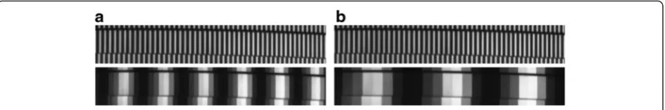
A contrasting experiment of a long strip is first carried out to demonstrate the effectiveness of the proposed method. The width of sinusoidal fringe is 16 pixels. One group possesses a the width ratio between the sinusoidal fringe and each stair phase of phase-coding fringe of 1:1 (Fig. 9(a)). In this case, p = 16, N = 8 and S = 8. The other group involves a corresponding ratio of 1:2 (Fig. 9b), in which p = 32, N = 8 and S = 4.
The reconstructed 3D results of the long strip with two strategies are shown in Fig. 10. Figure 10a, b corres-pond to width ratios of 1:1 and 1:2, respectively. The er-rors in Fig. 10a can be attributed to incorrect fringe order. Figure 10b displays accurate results after using the proposed method.
Measurement of a foam holder
A foam holder with two large holes was also employed to compare experimental results using four methods, Fig. 9Long strip modulated by fringe patterns at width ratios of (a) 1:1, and (b) 1:2
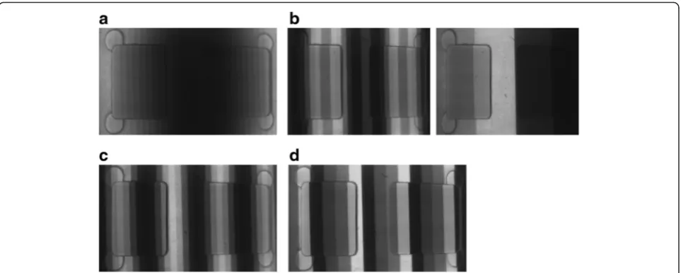
Fig. 11Phase-coding fringes captured from a foam holder using (a) Wang’s method, n = 1, p = 32, N = 32, S = 1 (b) Zheng’s method, the left one is n = 1, p = 32, N = 8, S = 4, and the right one is n = 2, p = 256, N = 4, S = 1, (c) Zhou’s method, n = 1, p = 32, N = 8, S = 4, and (d) the proposed method, n = 2, p = 64, N = 4, S = 4
including Wang’s, Zheng’s, and Zhou’s methods, as well as the proposed approach. The width of sinusoidal fringe is 32 pixels. Figure 11a shows a phase-coding fringe that uses Wang’s method. Figure 11b displays a set of phase-coding fringes that adopts Zheng’s technique. Figure 11c reveals a phase-coding fringe in gray-scale mode that employs Zhou’s approach, and Fig. 11d shows a set of phase-coding fringes that utilizes the proposed method. The reconstructed 3D results are exhibited in Fig. 12a–d, the 3D shape result of the proposed method overmatches that of the others. The RMSs of the height errors in Fig. 12a–d are 0.066, 0.049, 0.043 and 0.035 mm respectively.
Measurement of isolated objects
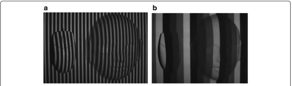
Another experiment that includes a complex face model and a computer mouse was provided to demonstrate that the proposed method can measure isolated objects with complicated shapes. The object modulated by si-nusoidal fringes is shown in Fig. 13a, the width of
sinusoidal fringe is 16 pixels, and the object modulated by phase-coding fringes is shown in Fig. 13b. The 3D result with phase error compensation [26] is presented in Fig. 14.
Measurement of a standard gauge block
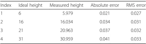
Four standard gauge blocks with different heights were measured using the proposed method to verify further the measurement accuracy. The measured area was approximately 500 mm × 800 mm. The width of sinusoidal fringe is 32 pixels, Fig. 15a, b show the four standard gauge blocks modulated by sinusoidal and phase-coding fringes, respectively. Figure 16 displays the 3D shape of the four standard gauge blocks ob-tained using the proposed method. Table 1 lists the absolute and RMS errors for each standard gauge block. The maximum absolute error is 0.041 mm, and the maximum RMS error is 0.033 mm. The quantita-tive analysis reveals the accuracy of the proposed method.
Fig. 13Fringe patterns: (a) sinusoidal, and (b) phase-coding fringes, n = 2, p = 64, N = 4, S = 4
Fig. 163D shape of four standard gauge blocks
Fig. 15Four standard gauge blocks modulated by corrected fringes: (a) sinusoidal fringe, and (b) phase-coding fringe, n = 2, p = 64, N = 4, S = 4
Table 1Experimental results on standard gauge blocks
(Unit: mm)
Index Ideal height Measured height Absolute error RMS error
1 6 5.979 0.021 0.027
2 16 16.034 0.034 0.031
3 21 20.963 0.037 0.032
Fig. 17Long strip modulated by fringe patterns at width ratios of (a) 1:1, n = 1, p = 21.33, N = 12, S = 4, (b) 2:1, n = 2, p = 42.66, N = 6, S = 4 (c) 3:1, n = 3, p = 64, N = 4, S = 4, and (d) 4:1, n = 4, p = 85.33, N = 3, S = 4
of the phase-coding fringe is given by (N=) 12, 6, 4, and 3, respectively. Figure 18 shows the corresponding 3D results. From the results, two conclusions are noted. One is that at the case of the different width ratio be-tween the sinusoidal fringe and each stair phase of phase-coding fringe, the measurement achieves a better result when S is close to N. This finding is easily under-stood because the fringe order is readily identified cor-rectly when N is small. The other is that the method can achieve measurement, although the phase-coding fringe intensity is lower. This condition is allowed be-cause this fringe based on phase code is resistant to sur-face contrast variations, ambient light, and camera noises. The phase-coding fringe in Fig. 17d is presented as an illustration.
Conclusion
A modified stair phase-coding fringe was designed, and a new phase unwrapping algorithm based on stair phase-coding fringe was presented. This method used a large number of codewords as much as the resolution ratio of CCD allows, it can correctly judge the fringe order, achieving accurate phase unwrapping. The width ratio between the sinusoidal fringe and each stair phase of phase-coding fringe is set to 1: n. Compared with other methods, the proposed method adopts a lower number instead of numerous codewords. Therefore, the proposed approach gains two merits. One is that it can improve the measurement accuracy, the other is that it can measure isolated objects with complicated shapes. In our future work, two issues remain to be addressed: correction of the non-uniformity of the stair phase-coding fringe during large-scene measurements and en-coding of a composite color pattern for the dynamic scene.
Acknowledgment
This project is supported by the National Natural Science Foundation of China (Grant No. 51365045,61462063), Shanghai Aerospace Science and Technology Innovation Fund (Grant No. SAST2015046).
Competing interests
The authors declare that they have no competing interests.
5. Jiang, C, Jia, S, Xu, Y, et al.: The application of multi-frequency fringe projection profilometry on the measurement of biological tissues. Bio-Med. Mater. Eng.26(s1), 395–403 (2015)
6. Liu, J, Tan, J, Zhao, C, et al.: Phase-shift resolving confocal microscopy with high axial resolution, wide range and reflectance disturbance resistibility. Opt. Express17(18), 16281–16290 (2009)
7. Zhao, H, Chen, W, Tan, Y: Phase-unwrapping algorithm for the measurement of three-dimensional object shapes. Appl. Opt.33(20), 4497–4500 (1994) 8. Li, J, Su, H, Su, X: Two-frequency grating used in phase-measuring
profilometry. Appl. Opt.36(1), 277–280 (1997)
9. Zhang, C, Zhao, H, Gu, F, et al.: Phase unwrapping algorithm based on multi-frequency fringe projection and fringe background for fringe projection profilometry. Meas. Sci. Technol.26(4), 045203 (2015) 10. Zhang, Y, Xiong, Z, Wu, F: Unambiguous 3D measurement from
speckle-embedded fringe. Appl. Opt.52(32), 7797–7805 (2013) 11. Feng, S, Chen, Q, Zuo, C: Graphics processing unit–assisted real-time
three-dimensional measurement using speckle-embedded fringe. Appl. Opt.
54(22), 6865–6873 (2015)
12. Sansoni, G, Corini, S, Lazzari, S, et al.: Three-dimensional imaging based on Gray-code light projection: characterization of the measuring algorithm and development of a measuring system for industrial applications. Appl. Opt.
36(19), 4463–4472 (1997)
13. Sansoni, G, Carocci, M, Rodella, R: Three-dimensional vision based on a combination of gray-code and phase-shift light projection: analysis and compensation of the systematic errors. Appl. Opt.38(31), 6565–6573 (1999) 14. Zheng, D, Da, F: Self-correction phase unwrapping method based on Gray-code
light. Opt. Lasers Eng.50(8), 1130–1139 (2012)
15. Liu, Y, Su, X, Zhang, Q: A novel encoded-phase technique for phase measuring profilometry. Opt. Express19(15), 14137–14144 (2011) 16. Wang, Y, Zhang, S: Novel phase-coding method for absolute phase retrieval.
Opt. Letters.37(11), 2067–2069 (2012)
17. Fu, Y, Wang, Y, Wan, M, et al.: Three-dimensional profile measurement of the blade based on surface structured light. Optik-Int. J. Light Electron Opt.
124(18), 3225–3229 (2013)
18. Zheng, D, Da, F: Phase coding method for absolute phase retrieval with a large number of codewords. Opt. Express20(22), 24139–24150 (2012) 19. Zhou, C, Liu, T, Si, S, et al.: An improved stair phase encoding method for
absolute phase retrieval. Opt. Lasers Eng.66, 269–278 (2015) 20. Chen, F, Su, X: Phase-unwrapping algorithm for the measurement of 3D
object. Optik-Int. J. Light Electron Opt.123(24), 2272–2275 (2012) 21. Xu, J, Liu, S, Wan, A, et al.: An absolute phase technique for 3D profile
measurement using four-step structured light pattern. Opt. Lasers Eng.
50(9), 1274–1280 (2012)
22. Xu, Q: System calibration technique of profilometry by projected grating. Opt. Tech.26(2; ISSU 142), 126–129 (2000)
23. Takeda, M, Mutoh, K: Fourier transform profilometry for the automatic measurement of 3-D object shapes. Appl. Opt.22(24), 3977–3982 (1983) 24. Malacara, D: Optical Shop Testing (Wiley Series in Pure and Applied Optics).
Wiley-Interscience, Canada (2007)
25. Zhou, L, Su, X, Wang, L: Analysis of errors introduced by detector nonlinearity in Phase Measuring Profilometry. Laser Journal3, 009 (2002) (in Chinese) 26. Zhang, S, Huang, PS: Phase error compensation for a 3-D shape
measurement system based on the phase-shifting method. Opt. Eng.