Transmission
Figure 12-1
PROCESS
TO
PROCESS
COMMUNICATION
12.1
TCP/IP Protocol Suite 5
Table 12.1
Figure 12-2
Figure 12-3
TCP
SERVICES
12.2
Figure 12-4
Stream delivery
Figure 12-5
Figure 12-6
Connection oriented service
Two tcp’s establish a connection between them
Data are exchanged in both direction
Connection is terminated
Reliable service
NUMBERING
BYTES
12.3
The bytes of data being transferred
The bytes of data being transferred
in each connection are numbered by TCP.
in each connection are numbered by TCP.
Example 1
Example 1
Solution
Solution
The following shows the sequence number for each
segment:
Segment 1
10,010 (10,010 to 11,009)
Segment 2
11,010 (11,010 to 12,009)
Segment 3
12,010 (12,010 to 13,009)
Segment 4
13,010 (13,010 to 14,009)
The value of the sequence number field in
a segment defines the number
of the first data byte
Figure 12-19
•
Source Port address:
Port number of the application
program
•
Destination Port:
Port number of the application
program in the host that is receiving the segment
•
Sequence Number:
Defines the number assigned to
the first byte of data contained in this segment. During
connection establishment each party uses a random
number generator creates an
Initial Sequence
Number (ISN)
•
Header Length: Value of this field can be
between 20 and 60 bytes
•Reserved: Reserves for future use
•
Window Size-
Defines the size of the window in
bytes that the other party must maintain
•Max size of the window is 65,535 bytes
•Determined by the receiver
•
Checksum- Pseudo header ,Mandatory
Figure 12-20
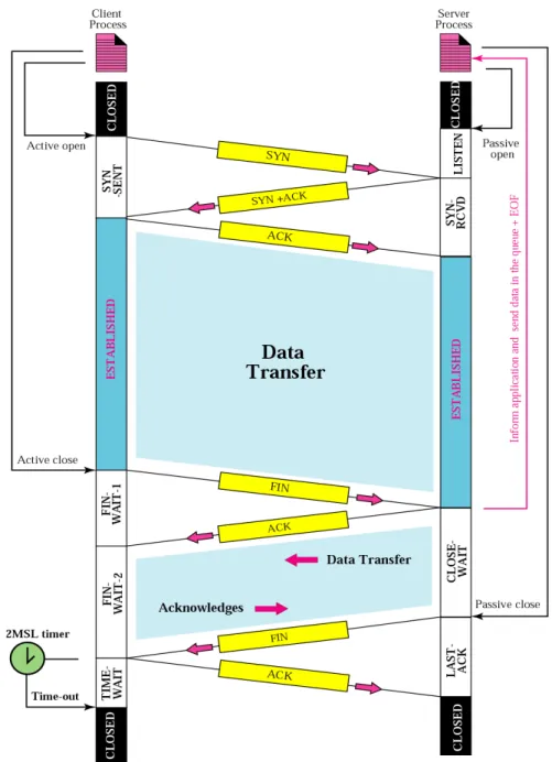
CONNECTION ESTABLISHMENT
DATA TRANSFER
Three way handshaking
1. Active open
2. Passive open
3. Simultaneous open
Figure 12-28
1. SYN Segment cannot carry data but it consumes one sequence number
• This segment is for synchronization of sequence numbers
• Chooses a random sequence number called ISN • No ack
2. SYN+ACK segment with two flag bits set SYN+ACK
• Dual Purpose: Server uses this segment to initialize a sequence number for numbering bytes sent from the server
• Server also acknowledges the receipt of SYN segment from the client by setting the ACK flag and displays the next Sequence number it expects to receive from the client. It contains the receiver window size rwnd to be used by the client.
Connection Establishment
• 3. Just an ack Segment . It acknowledges the receipt of
the second segment with the ACK flag and
acknowledgment number field
• Sequence number in this segment is the same as the one
in the SYN segment. ACK segment does not consume
any sequence numbers
•
When a malicious attacker sends a large number of
SYN segments to a server pretending that each of
them is coming from a different client by faking the
source IP addresses in the datagrams. Belongs to
denial of service attack
•
Soln : Limit of connection request during a specific
period of time
•
Filters out datagrams coming from unwanted source
addresses
•
To postpone resource allocation until the entire
connection is set up using cookie
Figure 12-29
DATA TRANSFER
• Pushing data- Sending TCP uses a buffer to store the stream of data coming from the app. Program. Receiving TCP buffers the data when they arrive and delivers them to application program when it is ready
•Ex: Consider an application program that communicates interactively with another application program. Application program on one site wants to send a keystroke to the application at the other site and receive an immediate response
•Application program at the sending site can request a push
operation. Sending TCP will not wait for the window to be filled •Sets push bit so that receiving TCP know that the segment includes data that must be delivered to the receiving application program as soon as possible
Urgent data
• Sending application pgm wants a piece of data to be read out of order by the receiving application pgm
• Ex: Sending app. Program is sending data to be processed by the receiving application program finds that everything is wrong. It wants to abort the process but it has already sent a huge amount of data.
• Soln is to send a segment with the URG bit set. Sending TCP creats a segment and inserts the urgrent data at the beginning of the segment. Urgement pointer field defines the end of the urgent data and start of normal data
Connection Termination
Three way handshaking
1. FIN segment can include the last chunk of data send by the client or it can be just a control segment
• FIN segment consumes one sequence number if it does
not carry data
2. Server TCP after receiving FIN segment it sends FIN+ ACK segment to confirm the receipt of FIN segment and at the same time announce the closing of connection
FIN+ACK segment consumes one sequence number of it does not carry data
3. Client TCP sends the last segment Ack segment to confirm the receipt of FIN segment
Half Close
• One end stop sending data while still receiving data
• Eg.: When the client sends data to the server to be sorted • Client half closes the connection by sending a FIN segment
• After half closing the connection data can travel from the server to the client and acknowledgements can travel from the client to server
• Data transfer from the client to the server stops. Server can however still send data
CONNECTION RESET
Denying a connection- Request the nonexistent port. Send a segment with its RST bit set
STATE
TRANSITION
DIAGRAM
12.13
Figure 12-30
TCP/IP Protocol Suite 40
Table 12.3
Figure 12-31
•Dotted Black lines- Represents the transition that server normally goes through
•Solid Black Lines- Represents the transition that client normally goes through
•Connection Establishment
•Client States: Client process issues a command to its TCP to request a connection to a specific socket address. This is called active open
•Client : TCP sends a SYN segment
•Server: TCP sends SYN+ACK segment
•Client process has no more data to send it issues a cmd called an active close
•Client TCP sends a FIN segment and goes to the FIN-WAIT-1 state
•When it receives the ACK for the sent FIN it goes to FIN-WAIT-2 state and remains there until it receives the a FIN segment from the server
•When FIN segment is received the client sends an ACK segment and goes to TIME-WAIT state and sets a timer for a time out value of twice the maximum segment lifetime (MSL)
•MSL is the maximum time a segment can exist in the Internet before it is dropped
•There are 2 reasons for the existence of TIME-WAIT state and the 2 MSL timer:
1. If the last ACK segment is lost the server TCP which sets a timer for the last FIN assumes that its FIN is lost and resends it
•If the client goes to the CLOSED state and closes the connection before the 2 MSL timer expires, server never receives the final ACK. Server cannot close the connection
•2 MSL timer makes the client wait for a duration (enough time for an ACK to be lost and a FIN to arrive)
•During the TIME-WAIT state a new FIN arrives the client sends a new ACK and restarts the 2 MSL timer
•Assume a client and server have closed a connection
•After a short period of time they open a connection with
the same socket address
•This new connection is called
incarnation
of the old one
•A duplicated segment from the previous connection may
arrive in the new connection and interpreted as belonging
to new connection if there is not enough time between two
connections
Figure 12-32
•Server State
•The server process issues an open command (before client open)
•Server TCP goes to the LISTEN state and remains there until it receives SYN segment
•When the server TCP receives a SYN segment it sends a SYN+ACK segment and goes to SYN-RECD state waiting for the client to send an ACK segment
•After receiving ACK segment it goes to Established state where data transfer takes place
•TCP remains there until it receives a FIN segment from the client TCP
•It then sends a FIN to the client to show that it is closing
the connection too and goes to LAST-ACK state
49
TCP/IP Protocol Suite 50
The common value for MSL is between
30 seconds and 1 minute.
Note:
FLOW
TCP/IP Protocol Suite 52
12.6 FLOW CONTROL
Flow control regulates the amount of data a source can send before
Flow control regulates the amount of data a source can send before
receiving an acknowledgment from the destination. TCP defines a window
receiving an acknowledgment from the destination. TCP defines a window
that is imposed on the buffer of data delivered from the application
that is imposed on the buffer of data delivered from the application
program.
program.
The topics discussed in this section include:
The topics discussed in this section include:
Sliding Window Protocol
Sliding Window Protocol
Silly Window Syndrome
TCP/IP Protocol Suite 53
TCP/IP Protocol Suite 54
A sliding window is used to make
transmission more efficient as well as to
control the flow of data so that the
destination does not become
overwhelmed with data.
TCP’s sliding windows are byte
oriented.
Note:
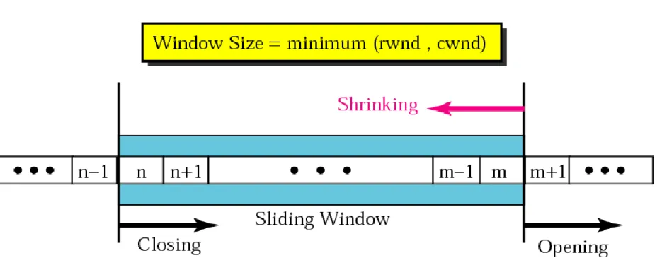
Flow Control
• Bytes inside the window are the bytes that can be in transit they can be sent without worrying about ack
• Window is opened, closed or shrunk
• Opening a window moves right wall to right. This allows more new bytes in the buffer that are eligible for sending • Closing window moves left wall to right. This means
some bytes have ack and the sender need not worry anymore
Flow Control
• Size of the window at one end is determined by
the
lesser
of
two
values:
receiver
window(rwnd) or congestion window(cwnd)
•
Receiver window
is the value advertised by the
opposite end in a segment
• It is the number of bytes the other end can
accept before its buffer overflows
•
Flow Control
• Ex 1: Shows an unrealistic example
• Sent Bytes 202
• 200 to 202 are sent not ack
TCP/IP Protocol Suite 58
Figure 12.21 Example 5
Ex 1: Shows an unrealistic example Sent Bytes 202
200 to 202 are sent not ack
•
Flow Control
•
Flow Control
TCP/IP Protocol Suite 61
Flow Control
Flow Control
• How can the receiver avoid shrinking the window in the previous example
Soln:
• To avoid the shrinking the sender window the receiver must wait until more space is available in its buffer (Window Shutdown)
SILLY
Silly Window Syndrome
• Ex:If TCP sends segments containing only 1 byte of
data , it means 41 byte datagram transfers only 1
byte of user data. Here the overhead is 41/1. which
denotes we are using the capacity of the networj
very inefficiently. This problem is called silly window
syndrome
• Syndrome Created by the Sender
Silly Window Syndrome
•
Nagle’s Algorithm:
• 1. Sending TCP sends the first piece of data it
receives from the sending application program even
if it is 1 byte
• 2. After sending the first segment, the sending TCP
accumulates data in the output buffer and waits until
either the receiving TCP sends an ack or until
enough data has accumulated to fill a max size
segment
Silly Window Syndrome
•
Syndrome Created by the Receiver
• Ex: Sender sends 4 k byte of data (receiver
capacity 4kbyte). Receiver appln pgm consumes 1
byte at a time
• Now the receiver application pgm reads the 1 byte
and announces the window size of 1 byte
• Again Inefficiency problem
Silly Window Syndrome
•
Delayed Ack:
It is not acknowledged until a decent
amount of space in its incoming buffer
•
Adv:
Reduces Traffic
In TCP, the sender window
In TCP, the sender window
size is totally controlled
size is totally controlled
by the receiver window value.
by the receiver window value.
However, the actual window size
However, the actual window size
Some Points about TCP’s Sliding Windows:
Some Points about TCP’s Sliding Windows:
1. The source does not have to send a
1. The source does not have to send a
full window’s worth of data.
full window’s worth of data.
2. The size of the window can be increased
2. The size of the window can be increased
or decreased by the destination.
or decreased by the destination.
3. The destination can send an
3. The destination can send an
TCP
OPERATION
12.14
Figure 12-33
Figure 12-34
TCP
Figure 12-36
TCBs