4
Emerging Technologies for 4G
4.1 Introduction
OFDM-based access techniques are the most appropriate candidate for 4G, as it has been discussed in Chapter 3. In order to provide the required quality of ser-vices to users of 4G, several key technologies will be used with OFDM. There-fore, the next task is to present and update information on key technologies, namely MIMO technology, radio resource management, software defined radio (SDR) communication system, mobile IP, and relaying techniques [1-175]. This chapter starts with the multiantenna technologies in Section 4.2. Multiantenna is one of the key technologies for mitigating the negative effects of the wireless channel, providing better link quality and/or higher data rate without consuming extra bandwidth or transmitting power. The use of multiple antennas at either receiver, transmitter, or both ends provides several benefits: array gain, interfer-ence reduction, diversity gain, and/or multiplexing gain. Section 4.3 focuses on the main radio resource management functions. They constitute a fundamental aspect for the provision of a variability degree of the quality of service and the effective explanation of the limited radio resource, thus representing a hot research area. The concept of SDR is one of the bridges between software pro-gramming and real hardware implementation. Section 4.4 defines radio commu-nication systems and summarizes the advantages of SDR. In addition, this section discusses the problems that must be overcome to realize the SDR com-munication system and explains the remarkable technologies developed to realize such a system. Section 4.5 deals with IP network issues: Mobile IP architecture, proposed for supporting mobility in Internet, is presented together with guide-lines behind mobility. Section 4.6 introduces the concepts of relaying techniques for 4G, and other enabling techniques are listed in Section 4.7.
4.2 Multiantenna Technologies
Recent years have witnessed an explosive growth of interest in studying and using multiple antenna techniques for wireless communication systems. Such a trend is motivated by the fact that several of the specifications foreseen for future wireless systems appear to be difficult, if not impossible, to fulfill with conven-tional single antenna systems. It is widely accepted that multiple antennas have the potential to increase the achievable data throughput, to enhance link quality (BER, QoS), and to increase cell coverage and network capacity, among others. Such a promising array of enhancements has contributed to speeding up the development in the field, both at academic levels, where countless techniques are developed, and in the industry, where solutions based on these techniques are being rapidly adopted in real systems.
Multiple transmit and receive antennas can be combined with various multiple access techniques such as TDMA, CDMA, and OFDM to improve the capacity and reliability of communications. Multiple-input multiple-output (MIMO) communication systems are regarded as an effective solution for future high-performance wireless networks. The use of multiple antennas at transmit-ter and receiver, popularly known as MIMO, is a promising cost-effective tech-nology that offers substantial leverages in making the anticipated 1-Gbps wireless links a reality.
Several efforts are currently underway to build non-line-of-sight (NLOS) broadband wireless systems. A MIMO wireless system (physical layer and MAC layer technology) using OFDM modulation for NLOS environments was suc-cessfully developed by NTT DoCoMo. In mobile access, there is an effort under the ITU working group to integrate MIMO techniques into the high-speed downlink packet access (HSDPA) channel, which is part of the Universal Mobile Telecommunications System (UMTS) standard. Lucent Technologies recently announced a chip for MIMO enhancement of UMTS/HSDPA but has released no further details. Preliminary efforts are also underway to define a MIMO overlay for the IEEE 802.11 standard for WLANs under the newly formed Wireless Next Generation (WNG) group. Moreover, many other com-panies also proposed advanced MIMO schemes for the IEEE 802.16 standard. In this chapter, we provide an overview of MIMO technology and explain recent research directions and results.
4.2.1 Overview of MIMO Technology
antenna elements (typical interelement spacing is at least a fewλ). In this chap-ter, we will explore the latter approach where the fading processes associated with any two possible transmit-receive antenna pair can be assumed to be inde-pendent. The fact that a MIMO system consists of a number of uncorrelated concurrent channels has been exploited from two different perspectives. First, from a pure diversity standpoint, one can enhance the fading statistics of the received signal by virtue of the multiple available replicas being affected by pendent fading channels. By sending the same signal through parallel and inde-pendent fading channels, the effects of multipath fading can be greatly reduced, decreasing the outage probability and hence improving the reliability of the communication link [1]. In the second approach, referred to as spatial multiplexing [2], different information streams are transmitted on parallel spa-tial channels associated with the transmit antennas. This could be seen as a very effective method to increase spectral efficiency. In order to be able to separate the individual streams, the receiver has to be equipped with at least as many receive antennas as the number of parallel channels generated by the transmitter in general. For a given multiple antenna configuration, one may be interested in finding out which approach would provide the best possible or desired performance.
4.2.1.1 Diversity
Space-time coding (STC) is a hybrid technique that uses both space and tempo-ral diversity in a combined manner. There are two forms of STC namely space-time block code (STBC) and space-time trellis code (STTC). STBC effi-ciently exploits transmit diversity to combat multipath fading while keeping decoding complexity to a minimum. Tarokh et al. [3] showed that no STBC can achieve full-rate and full-diversity for more than two transmit antennas, and proposed a 3/4 rate, full-diversity code for four transmit antennas. A full-rate quasi-orthogonal (QO) STBC was proposed by Jafarkhani [4] for four transmit antennas based on Alamouti orthogonal STBC [1]. In this case, the transmis-sion matrix is given by
C A A
A A
= −
=
− −
−
∗ ∗
∗ ∗ ∗ ∗
∗
12 34
34 12
1 2 3 4
2 1 4 3
3
x x x x
x x x x
x −
− −
∗ ∗ ∗
∗ ∗
x x x
x x x x
4 1 2
4 3 2 1
(4.1)
4.2.1.2 Mixed (Hybrid Diversity and Spatial Multiplexing)
This mode combines diversity and spatial multiplexing by transmitting from four transmit antennas, each space-time block coded with the basic Alamouti scheme of order two [1]. The transmission matrix of the space-time block cod-ing for theith data stream,i=a,bis given by
(
)
(
)
(
)
(
)
Ai
x i x i
x i x i
= − ∗ ∗ 1 2 2 1 (4.2)
To decode the data, minimum mean square error (MMSE) and zero forc-ing (ZF) receivers can be employed. For the MMSE receiver, we assume that the transmitted matrix is
[
an2(
k a)
, 2n+1(
k b)
, 2n(
k b)
, 2n+1(
k)
]
T, where a and bindicate different signal streams. First, the tap weight vector and decoding layer order are determined. If the first decoding layer isa, the procedure can be repre-sented by
(
)
(
)
(
(
)
)
(
)
$ $ a ka k decision
k k k n n H H n 2 2 1 1 2 + = w
w y (4.3)
The interference from the original signal can be subtracted usinga$2n
(
k)
and a$2n+1
(
k)
; accordingly, the other stream can be decoded as follows:(
)
(
)
[
(
)
(
)
]
(
(
)
)
(
)
(
)
′ = − + +yn yn h h
n n
n n
k k k k a k
a k b k b k 1 2 2 2 1 2 2 1 $ $ $
$ =decision
(
(
kk)
)
′n(
k)
h
h y
3 4
(4.4)
Note that for comparative purposes we can also employ maximum likeli-hood (ML) decoding (explained in next section) to obtain the optimum perfor-mance, which was used as our baseline reference.
4.2.1.3 Spatial Multiplexing
by linearly weighting the received signals so as to satisfy some performance related criterion, such as ZF or MMSE. This linear nulling approach is viable, but superior performance is obtained if nonlinear techniques are used. One par-ticularly attractive nonlinear alternative is to exploit symbol cancellation as well as linear nulling to perform detection. By using symbol cancellation, the inter-ference from the already-detected components is subtracted from the received signal vector, effectively reducing the overall interference. Here we will consider ordered successive interference cancellation with ZF and MMSE. Also, a ML decoding receiver will be used as a reference.
It is assumed that theHij
(
k)
is the channel coefficient from jth transmitantenna to ith receive antenna and w is white Gaussian noise with covariance
matrixCw
[
wwH]
INR E
= =σ2 where N
Ris the number of received antennas.
Then, the received signal vector can be written as follows:
(
)
(
)
(
)
(
)
yn k =H k xn k +w k (4.5)
where the index k denotes the kth subcarrier, y
(
k)
=[
y k1(
)
LyNR(
k)
]
T,(
)
[
(
)
(
)
]
x k = x k1 LxNR k T, andw(k) is the (NR×1) noise vector. Maximum Likelihood Decoding (Optimal Solution)
The ML detection ofx(k) can be found by maximizing the conditional probabil-ity densprobabil-ity function and this is equivalent to minimizing the log-likelihood function:
(
)
( ){
(
)
(
)
}
{
(
)
(
)
}
$ min
x y Hx y Hx
x
k k k k k
k
H
= − − (4.6)
where,x
(
k)
∈all possible constellation sets.It is well known that ML decoding is characterized by a high implementa-tion complexity, and thus, suboptimal but practically implementable soluimplementa-tions are considered next.
Ordered Successive Interference Cancellation (OSIC)
Instead of the ML decoding approach, linear detection techniques can be used (i.e., ZF and MMSE). To improve the linear detection techniques, we try to decode according to received signal strength, and extract the decoded signal from the received signal. This approach is referred to as D-BLAST or V-BLAST [2] according to the transmitted signal structure, where D stands for diagonal and V for vertical. For simplicity, we consider the OSIC.
• Step 1: Compute the tap weight matrix W.
• Step 2: Find the layer with maximum SNR.
• Step 3: Detection
(
)
(
)
z nk k n
H
=W y
(
)
[
(
)
]
$
x nk =decision z nk .
• Step 4: Interference cancellation
(
)
(
)
(
)
y n =y n −h$k n
[
]
H= h1,L,hk−1, ,0 hk+1,L,hT
• Step 5: Repeat Step 1 to 5 until all symbols are detected.
Zero-Forcing. The cost function can be expressed as
(
)
(
)
{
}
{
(
)
(
)
}
JZF k k k k
H
= y −Hx$ y −Hx$ (4.7)
SinceJZFis a convex function overx k$
(
)
,x k$(
)
can be determined by usingthe minimum limit. Then, the tap weight vector is given by
{
}
W= H HH −1HH
(4.8)
Minimum Mean Square Error. To take into account the noise variance, the cost function can be expressed as
(
)
(
)
{
}
{
(
)
(
)
}
[
]
JMMSE E k k k k
H
= y −Hx$ y −Hx$ (4.9)
Using a similar method as in the ZF detection method, the weight vector results in
{
}
W= HH+σ2I −1HH (4.10)
4.2.2 Adaptive Multiple Antenna Techniques
Recently some authors have considered the diversity-spatial multiplexing prob-lem. In [5], the fundamental trade-off between diversity and spatial multiplexing is explored by Zheng and Tse. A scheme based on switching between diversity and spatial multiplexing is proposed by Heath and Paulraj [6]. Authors have considered a fixed rate system in which the receiver adaptively selects one of the two transmission approaches based on the largest minimum Euclidean distance of the received constellation. The receiver informs its selec-tion to the transmitter via a 1-bit feedback channel. To ensure a fixed bit rate, the diversity scheme uses modulation with a higher order than that used by its counterpart spatial modulation case. Skjevling et al. presented a hybrid method combining both diversity and spatial multiplexing [7]. The proposed approach optimally assigns antennas to a given (fixed) transmission scheme combining diversity and spatial multiplexing. Antenna selection is based either on full chan-nel feedback or long-term statistics. Gorokhov et al. studied the relationship between multiplexing gain and diversity gain in the context of antenna subset selection [8], thereby extending the recent result by Zheng and Tse [5].
4.2.3 Open-Loop MIMO Solutions
Alamouti developed a remarkable orthogonal FDFR code forNT =2 transmit antennas [1], requiring a simple linear decoder at the receiver. Tarokh et al. [3] proved that a FDFR orthogonal code only exists forNT =2 and proposed some space-time block codes forNT >2 attaining full-diversity but not full-rate. In [4] a quasi-orthogonal full-rate code is proposed by Jafarkhani, though full-diversity gain cannot be attained. Based on space-time constellation rota-tion, Xin et al. [9] and Ma et al. [10] proposed a FDFR encoder for an arbitrary number of transmit antennas. For an even number of transmit antennas, Jung et al. [11] obtained coding gain with a FDFR space-time block code by serially concatenating the Alamouti scheme with the constellation rotation techniques used in [9, 10]. Although the Alamouti-based space-time constellation rotation encoder (A-ST-CR) of [11] can effectively achieve full-diversity and full-rate, the decoding complexity is an issue and its practical implementation becomes prohibitive, even for a small number of transmit antennas (e.g.,NT =4). This is in virtue of the high computational complexity required by the ML decoding algorithm.
rotation coding scheme is very significant at the receiver, where, due to the pro-vided signal decoupling, the decoding complexity is significantly reduced. It is shown in this chapter that the proposed method attains the same performance as the scheme presented in [11] with a substantial complexity reduction.
References [9-11] use a precoder based on the Vandermonde matrix for attaining a FDFR system. After multiplying the received signal x by the Vandermonde matrix, each component of vector r combines all the symbols as can be observed in the next basic precoder equation.
r= x=
Θ 1 4 1 1 1 1 0 1 0 2 0 3 1 1 1 2 1 3 2 1 2 2 2 3 3 1 3 2 3 3
α α α
α α α
α α α
α α α
= x x x x r r r r 1 2 3 4 1 2 3 4 (4.11)
whereαi =exp
(
j2π(
1 1 4+)
N)
, i=0 1, ,K,N −1.Xin [9] and Ma [10] use a diagonal channel matrix after multiplying the information symbols by the Vandermonde matrix. This linear precoding is referred to as the constellation rotation operation. Notice that the coding advan-tage of [9, 10] is not optimized, although the schemes successfully achieve FDFR. Jung [11] improves the coding advantages by concatenating the constel-lation rotating precoder with the basic Alamouti scheme, resulting in the following transmitted signals:
S= −
− ∗ ∗ ∗ ∗ r r r r r r r r 1 2 2 1 3 4 4 3 0 0 0 0 0 0 0 0 (4.12)
At the receiving end, the signal can be written as
y 1 2 4 = = − ∗ ∗ ∗ ∗ y y y y h h h h h h 3 1 2 2 1 3 4 1 2 0 0 0 0 0 0
0 0 h h
r r r r n n n n 3 4 1 2 3 4 1 2 3 4 ∗ ∗ ∗ ∗ − +
=Hr n+ (4.13)
Note that since r1, r2, r3, r4 already sums over x1 ~x4through the
andr2,r3). Consequently, the Vandermonde matrix for the precoder need not be
of size 4, but smaller. Based on this observation, we can use a puncturing and shifting operation after the constellation rotation process resulting in a new precoder. r r 1 3 1 3 0 1 2 1 1 3 2 4 2 1 2 1 1 , , = = = r r x x r r α α 4 1 1 3 1 2 4 1 4 1 4 1 2 1 1 = = α α x x r r or
r, =
= = 1 2 1 1 1 2 1 0 1 3 1 1 4 2 3 2 3 1 1 α α α x x r r r , 1 2 1 2 3 α
xx
(4.14)
After puncturing and shifting, the encoder can be defined as
1 2
1 0 0
0 0 1
1 0 0
0 0 1
1 2
1 0 0
0 0 0 1 1 1 2 1 3 1 0 1 α α α α α or 1
0 0 1
1 0 0
1 1 2 1 3 1 α α α (4.15)
Recently, Zafar et al. proposed a low decoding complexity (symbol by symbol decoding) improved space-time code with full-diversity for three and four transmit antennas configurations [13]. The following is the format obtained after modifying the transmission matrix:
s=
+ − +
+ −
+ − +
x jy x jy
x jy x jy
x jy x jy
x
1 3 2 4
2 4 1 3
3 1 4 2
4
0 0
0 0
0 0
0 0 + −
jy2 x3 jy1
(4.16)
wherexi =siI cosθ−siQ sinθ, yi =siI cosθ−siQ sinθ, andθ=tan−1
(
1)
3 . Thecomplex symbolssitake values from a QAM signal set. Note that we already
sep-arated the encoder into two parts, so a Vandermonde matrix of order two should be used. The decoding computational complexity is significantly reduced com-pared to that of Jung’s in [11].
4.2.4 Closed-Loop MIMO Solutions
4.2.4.1 Antenna Grouping
The rate 1 transmission code for four transmit-antenna base stations in the IEEE 802.16e is
A s s s s s s s s = − − ∗ ∗ ∗ ∗ 1 2 2 1 3 4 4 3 0 0 0 0 0 0 0 0 (4.17)
Note that this scheme does not achieve full-diversity.
The effective channel model Heffis orthogonal and it can be written as
follows:
H Heff
H eff = ρ ρ ρ ρ 1 1 2 2
0 0 0
0 0 0
0 0 0
0 0 0
, (4.18)
whereρ1 = h1 2+h2 2 and ρ2 =h3 2+h4 2, beingh kk, =1 2 3 4 the channel, , , coefficient associated with thekth transmit antenna.
If the BS can use channel state information, the performance of the exist-ing matrix A approaches the performance of the FDFR STC in section 4.2.3 by using the following equation:
arg min _
antenna pairρ1−ρ2 (4.19)
Letdmin2 be the corresponding minimum distance of the normalized unit
energy constellation. The 2R −QAM Euclidean distance equation
(
)
d R
min
2 =12 2 −1 will be used, corresponding to QAM modulation for
diver-sity. Using this Euclidean distance equation, we can estimate the error probabil-ity as
P N Q E
N d e e s ≤ 0 2 min (4.20)
wheredmin2 is the squared Euclidean distance of the received signal, andNeis the
(
)
(
)
Q x =1erfc x
2 2 , where erfc is the complementary error function. For
STC, the minimum distance of the diversity constellation at the receiver can be shown to be
(
)
(
(
)
(
)
)
d a b c d
N d
F F
T
min min
min , , ,
2
2 2
2
H ≤ H H (4.21)
where (a, b) and (c, d) are antenna grouping index and H F is the Frobenius norm of matrix H. The details for derivation follow the derivation procedure of the maximum SNR criterion for code design.
Figure 4.1 shows the system block diagram, which makes use of a grouper to select the antenna pair based on feedback channel information from the MS.
The performance of the proposed scheme is shown in Figure 4.2. At BER =10−3point, the proposed scheme outperforms the conventional STC without antenna grouping by 3.5 dB.
The rate 2 transmission code for four transmit antennas in the current IEEE 802.16 standard [1] is
Tx. antennas
Matrix A1 or A2 or A3
Alamouti encoder
Alamouti encoder
f2
r
f1
2 bits feedback [s(1) s(2)]T
[s(3) s(4)]T
s
B
s s s s
s s s s
s s s s
s s s s
=
− −
− −
∗ ∗
∗ ∗
∗ ∗
∗ ∗
1 2 5 7
2 1 6 8
3 4 7 5
4 3 8 6
(4.22)
Transmission matrix B for rate 2 can be improved with antenna grouping information. The BS can group antennas 0 and 1 for the first diversity pair and antennas 2 and 3 for the second diversity pair. In matrix form, this can be expressed as follows:
B
s s s s
s s s s
s s s s
s s s s
1
1 2 5 7
2 1 7 5
3 4 6 8
4 3 8 6
=
− −
− −
∗ ∗
∗ ∗
∗ ∗
∗ ∗
(4.23)
QPSK, Rayleigh flat fading
0 2 4 6 8 10 12 14
SNR 100
10−1
10−2
10−3
10−4
BER : Matrix A w/o antenna grouping BER : Matrix A w/ antenna grouping
Considering different grouping index, the transmission matrix B can also be expressed as
B
s s s s
s s s s
s s s s
s s s s
2
1 2 5 7
2 1 7 5
4 3 8 6
3 4 6 8
= − − − − ∗ ∗ ∗ ∗ ∗ ∗ ∗ ∗ = − − − − ∗ ∗ ∗ ∗ ∗ ∗ B
s s s s
s s s s
s s s s
s s
3
1 2 5 7
3 4 6 8
2 1 7 5
4 3 ∗ ∗ ∗ ∗ ∗ ∗ ∗ = − − s s B
s s s s
s s s s
s s s
8 6
4
1 2 5 7
4 3 8 6
2 1 7 s
s s s s
B
s s s s
s s s
5
3 4 6 8
5
1 2 5 7
3 4 6
∗ ∗ ∗ ∗ ∗ ∗ − − = − − − − = − − ∗ ∗ ∗ ∗ ∗ ∗ s
s s s s
s s s s
B
s s s s
8
4 3 8 6
2 1 7 5
6
1 2 5 7
∗ ∗ ∗ ∗ ∗ ∗ ∗ − −
s s s s
s s s s
s s s s
4 3 8 6
3 4 6 8
2 1 6 5
(4.24)
At the mobile, the optimum transmission matrix is determined based on the following criteria. LetYri be the received signal at the ith symbol time at the
rth receive antenna, andht,rdenote the channel parameter between theht,th
trans-mit and rth receive antenna. When the number of receive antennas is two, the received signal can be represented as
(
)
y=X HW s v+ (4.25)
wherey =
[
y1 1, y1 2∗, y2 1, y2 2∗,]
T,s=[
s s s s]
T
1 2 3 4 , v is the noise
vector,H=
h h h h
h h h h
1 1 2 1 3 1 4 1 1 2 2 2 3 2 4 2
, , , ,
, , , ,
, X(·) is a function of 2-by-4 input
ma-trix, which is defined as
X a b c d
e f g h
a b c d
b a d c
e f g h
f e h g
= − − − − ∗ ∗ ∗ ∗ ∗ ∗ ∗ ∗ (4.26)
At the mobile station, the index of the transmission matrix
B qq, =1 2 3, , ,K6is determined based on the following criteria:
(
)
(
)
(
)
[
]
q abs
l l l
= +
=
arg min det det
, , , ,
1K6 H 1 H 2 (4.27)
whereHl,1is the first two columns ofHWl, andHl,2is the last two columns of
HWl. Note that the antenna grouping matrix selection rule in (4.27) is
equiva-lent to the following rule:
(
)
(
)
(
)
[
]
q trace
l l
H
l
=
=
− arg min
, , 1 6
1
K X HW X HW (4.28)
Alternate criteria for the antenna grouping can be applied to determine antenna group index. For example, minimize BER, MMSE, and so forth.
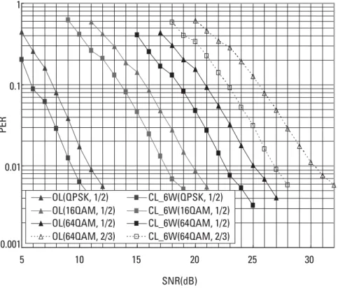
We compare the proposed antenna grouping-based closed-loop STC with open-loop STC for four transmit-antenna rate 2 STC. In Figure 4.3, packet
0.001 0.01 0.1 1
5 10 15 20 25 30
SNR(dB) OL(QPSK, 1/2) CL_6W(QPSK, 1/2) OL(16QAM, 1/2) CL_6W(16QAM, 1/2) OL(64QAM, 1/2) CL_6W(64QAM, 1/2) OL(64QAM, 2/3) CL_6W(64QAM, 2/3)
PER
error rates (PERs) of the proposed antenna grouping method and the conven-tional open-loop STC (matrix B) method are compared in the pedestrian A channel with 3 km/h. One frame feedback delay is reflected in the simulation, and an MMSE linear detector is used at the receiver.
When the correlation coefficient is 0.7 (Figure 4.3), the proposed antenna grouping with 3-bit feedback outperforms the conventional STC without antenna grouping more than 1.8 dB at PER=10−2(1.8 dB for 1/2 rate QPSK, 2.5 dB for 1/2 rate 16QAM, 2.4 dB for 1/2 rate 64QAM, and 3.2 dB for 2/3 rate 64QAM). As a higher MCS level is used, the performance gain is increased.
4.2.4.2 Codebook-Based Closed-Loop MIMO
The codebook words are employed in the feedback from mobile station (MS) to base station (BS). The MS learns the channel state information from downlink and selects a transmit beamforming matrix for the codebook. The index of the matrix in the codebook is then fed back to the BS. Each codebook corresponds to a combination of Nt, Ns, and Ni, which are the numbers of BS transmit
antennas, available data streams, and bits for the feedback index, respectively. Once Nt, Ns, and Ni are determined in the MS, the MS will feed back the
codebook index of Nibits. After receiving an Nibit index, the BS will look up
the corresponding codebook and select the matrix (or vector) according to the index. The selected matrix will be used as the beamforming matrix in MIMO precoding.
4.3 Radio Resource Management
As the evolution of wireless networks allows for an increasingly wide range of services, the Radio Resource Management (RRM) function, which divides the available resources amongst competing applications, is receiving increased atten-tion. There are several reasons that render RRM very important [49-75]:
1. RRM functions allow the support of a range of different requirements from the various services that the wireless network is required to support.
2. RRM may ensure the planned coverage (i.e., the area where the service is supported) for each service.
3. RRM may optimize capacity utilization.
4.3.1 QoS Requirements
In order to guarantee a satisfactory end user quality, the transmission of a data flow, which is originated by the application, has to satisfy certain requirements that define the QoS profile for the information data stream of interest. Usually, the QoS attributes for a particular application/service are: required throughput, maximum acceptable delay, maximum acceptable delay jitter, and maximum acceptable bit error rate.
From the end user point of view, the following issues must be taken into account [53]:
• End users only care about the degree of QoS, and not about how it is provided.
• Only the QoS perceived by end user matters.
• The number of “user defined/user controlled” parameters has to be at a minimum.
• A derivation/definition of QoS attribute from the application require-ments has to be simple.
• End-to-end QoS has to be provided.
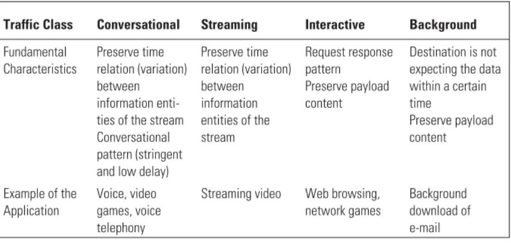
A very frequent classification of the service class is based on the applica-tion/service’s delay requirement. For example, in the UMTS standardization the following four service classes are defined: background class, interactive class, streaming class, and conversational class. The main difference between these classes is the delay sensitivity of the traffic. The conversational class is the most delay sensitive, while the background class is the most delay tolerant. Table 4.1 summarizes the UMTS QoS classes’ main characteristics.
In the standardization the definition of QoS attributes are the same for GPRS Release 99 and UMTS. The QoS attributes for General Packet Radio Service (GPRS) Release 97/98 can be mapped on the Release 99 UMTS attrib-utes as specified in [53]. However, the set of QoS attribattrib-utes in UMTS is much larger than the set specified in GPRS Release 97/98 (Figure 4.4).
The throughput requirement is dependent on the information source. A throughput of 12 Kbps would be enough in order to transfer speech with GSM quality. For an audio stream with stereo quality, the throughput requirement is higher than 32 or 64 Kbps, while for a video communication it is higher than 128 Kbps.
packet retransmissions). The use of error correction mechanisms is rather lim-ited by the delay requirement (e.g., for the interactive class). For the streaming and conversational classes, the acceptable BER depends on the type of informa-tion; for speech an acceptable BER is on the order of 10−2or 10−3and it may be even smaller for video transfer.
The application may specify its QoS requirements to the network by requesting a radio access bearer (RAB) with any of the specified traffic type, maximum transfer delay, delay variation, bit error rates, and data rates. In
Table 4.1 UMTS QoS Classes
Traffic Class Conversational Streaming Interactive Background
Fundamental Characteristics
Preserve time relation (variation) between information enti-ties of the stream Conversational pattern (stringent and low delay)
Preserve time relation (variation) between information entities of the stream
Request response pattern
Preserve payload content
Destination is not expecting the data within a certain time
Preserve payload content
Example of the Application
Voice, video games, voice telephony
Streaming video Web browsing, network games
Background download of e-mail
Release 97/98 Release 99 / UMTS
Precedence Reliability
Delay Throughput
Traffic class Traffic handling priority
SDU error ratio Residual bit error ratio Delivery of erroneous SDU
Max bit rate [Kbps] Allocation/retention priority
Delivery order Max SDU size Mapping
practice, it should be possible to define the main RAB characteristics from the service quality requirements:
• The transmission rate of RAB should be determined by the bandwidth requirement of the information source.
• The choice of dedicated or shared RAB should be based on the require-ment for the maximum delay and delay jitter.
• The SNIR requirement, channel coding, and interleaving for the RAB should be based on the BER requirement.
4.3.2 General Formulation of the RRM Problem
Let us assume a cellular network with M mobiles in the service area and denote withB={1, 2, ..., B} the set of all BSs used to provide the necessary coverage. Denote with C the number of available orthogonal channels in the system (i.e., the system capacity). The numbered set of all available channels isC={1, 2, ..., C}. The channels orthogonality could be established in different ways, such as in time and frequency domain in GSM or in the code domain in Wideband (W-CDMA). In GSM, as a representative of 2G systems, there is an intrinsic upper limit on the system capacity since the upper bound is the number of fre-quencies multiplied with eight time slots. On the other hand, in the WCDMA CDMA scheme, the set of orthogonal channels C is practically infinite and the capacity is determined by the interference condition in the system. A WCDMA system is, therefore, interference limited.
The link (power) gain matrix G characterizes the radio conditions in the system:
G
G G G
G G G
G G G
M M
B B BM
=
11 12 1
21 22 2
1 2
L L
L
.... (4.29)
The matrix elementGijrepresents the link gain between the BSiand MSj;
M represents the number of active mobiles. The gain matrixGis dynamic, the dimension M is changing, based on the offered load, and each element Gij
changes with the mobile movement. The radio resource management, taking into account the link gain matrixG, assigns [51]:
3. The transmit power of the BS and of the mobile.
The assignments 1 through 3 should maximize the number of users with a sufficient QoS. As outlined in the previous section, providing a stringent defini-tion of the QoS for a communicadefini-tion service is a complex problem. A simple measure of the QoS-namely, the signal-to-interference+noise ratio (SNIR)-is here considered. This measure is strongly connected with the performance mea-sures as the bit or frame error probability. Therefore, assignments 1 through 3 aim at maximizing the number of users for which the following inequality holds, for both the uplink (mobile-to-access port) and the downlink (access port-to-mobile):
SNIR P G
P G N j M
j
j jj
m jm jm M
m j
j =
+ ≥ =
≠
∑
θ γ 1,K, (4.30)In (4.30), SNIRj denotes the SNIR at the receiver;Pj is the transmitter
power used by the end userj;θjmis the normalized cross-correlation between the
signal of interest and the interfering signal from the mobilem(other thanj);N
denotes the thermal noise power at the access port; and while j is the target SNIRof the service that is being used by the mobile j.
4.3.3 RRM in Future Wireless Systems
In this section, future RRM developments in wireless LANs and general RRM issues in mobile ad hoc networks (MANETs) are presented.
The Broadband Radio Access Network (BRAN) working group in ETSI is standardizing a wireless LAN for broadband radio access up to 54 Mbps. This new standard is called HIPERLAN/2 and includes physical layer and radio link control and data link control standards (see [61-65]). The interfaces toward other networks (e.g., UMTS) are made via specific design of convergence sublayers. The physical layer of HIPERLAN/2 is aligned with the physical layer of the IEEE 802.11a wireless LAN system [65]. Note here that wireless broad-band networks based on the IEEE 802.11a standard became commercially avail-able in 2002. Among the most important RRM functions in these WLAN systems are the link adaptation function and the radio resources allocation in the MAC frame.
the pair modulation/coding scheme to optimize the throughput based on mea-sured PER, signal level, packet size, and so forth. Extensive analysis of the physi-cal layer performance of these two WLAN systems can be found in [63].
The MAC layer at the two WLAN standards is different. HIPERLAN/2 uses TDMA/TDD medium access with frame structure, as presented in Figure 4.5.
The allocation of radio resources is centrally scheduled by the access point (AP), which allows for implementation of scheduling algorithms, QoS differen-tiation, and resource reservation for services with stringent delay and delay varia-tion requirements.
The duration of the broadcast channel (BCH) is fixed. Through these channels the relevant system information is conveyed to the terminals. The duration of the frame control channel (FCH), downlink (DL) and uplink (UL) phase, direct link (DiL) phase, and random channel (RCH) is dynamically adapted to the current load conditions of the AP. DiL phase is present if there are mobile terminals directly communicating on a peer-to-peer basis. Requests for the radio resources are signaled via the RCH, where contention for time slots is present. If scheduled data is transmitted, then FCH is present and it signals the frame structure. The transmission in the DL phase (from the AP to the ter-minals) and UL phase (from terminals to the AP) is contention free. The alloca-tion of resources is signaled via the access feedback channel (ACH), as an answer to the resource request received via the RCH from the previous MAC frame.
The IEEE 802.11a standard, however, has a MAC scheme based on carrier sense multiple access with collision avoidance (CSMA/CA). A mobile terminal before transmission of data senses the radio channel. If the channel is free then the transmission can commence. Otherwise, an exponential back-off period is implemented before attempting the following packet transmission. This type of MAC (also known as distributed coordination function) makes the IEEE 802.11a standard more suitable for ad hoc wireless networks and non-real-time (background or interactive) type of applications. It should be mentioned that the standard also has contention-free MAC via the point coordination function (PCF), but this alternative is optional even though it could support real-time services. The advantage of the CSMA/CA is, however, the avoidance of a cen-tralized scheduler that coordinates the radio transmissions.
BCH FCH ACH DL phase DiL phase UL phase RCH 2 ms
Mobile ad hoc network, (MANETs) are also receiving attention in recent years. In Interent Engineering Task Force (IETF) there is a special working group (MANET working group) that investigates the routing protocols in ad hoc network. These networks are described by the IETF MANET group (source IETF MANET group):
A MANET is an autonomous system of mobile routers (and associated hosts) connected by wireless links, the union of which forms an arbitrary graph. The routers are free to move randomly and organize themselves arbitrarily; thus, the network’s wireless topology may change rapidly and unpredictably. Such a network may operate in a stand-alone fashion, or may be connected to the larger Internet.
Currently, there are many research activities in the RRM field for MANETs. Due to the specific characteristics of MANETs, such as dynamic topology, limited node performance, distributed algorithms, and so forth, the development of RRM functions is a difficult task. The most important factors in MANETs are the coverage (or connectivity) and the capacity [66, 67]. An extensive field of research is QoS-aware routing (see [68] for one typical exam-ple) and MAC with QoS support [69]. A common MAC design for MANETs is driven by the hidden/exposed terminal problem. However, the QoS constraints for particular applications require from the MAC layer additional functionalities to provide certain guarantees and to make distinctions among different types of connections. Furthermore, MAC has to interact with QoS-aware routing in an appropriate way to provide the required communication quality over the whole path from source to destination (i.e., over the multiple hops). The current MAC proposals [69] that support QoS provisioning and differentiation are based on resource reservation along the connection’s path, and differentiation between non-real-time and real-time connection establishment and maintenance.
The recent important development in the RRM field for multimedia wire-less communication is that for systems beyond UMTS. In these systems the last wireless hop towards the end user could be carried over different radio access networks. Here, the interworking of UMTS, WLAN or HIPERLAN/2, and GSM/GPRS networks will play an important role. For example, the wireless operators could have in their coverage areas multiple possibilities for wireless communications via different radio access networks, as presented in Figure 4.6.
4.4 Software Defined (SDR) Radio Communication Systems
As the number of wireless communication systems that users can use increase, there has been increasing demands for the coexistence of several mobile telecom-munication services; for example, GSM, or IS-54, or IS-136, or IS-95, Japanese Personal Digital Cellular (PDC) or Personal Handy Phone System (PHS) or IMT-2000 system. Currently, if one wants to be globally connected, more than one terminal may be needed, though it is becoming more common to find multistandard terminals.
A person working on SDR is expected to be familiar with any communica-tion system whether it is for radio transmission or multiple access purposes. Such schemes can be developed and written in programming languages like MATLAB or C. These computer simulation languages have a good relationship with software languages that configure digital signal processing hardware (DSPH) such as digital signal processors (DSP), field programmable gate arrays (FPGA), and application-specific integrated circuits (ASIC). A typical software language for DSPH is very high speed integrated circuit hardware description language (VHDL) and Verilog-HDL. DSPH has been utilized to configure the mobile terminals and base stations of mobile communication systems. DSPH is
Common radio resource management
GERAN
IEEE 802.11a HIPERLAN/2
UTRAN
a general-purpose language, and the configuration can be programmed by downloading digital signal processing software (DSPS). This means that users can download DSPS describing the desired elemental components into the DSPH of only one terminal. This is the basic concept of an SDR communication system [76-90].
Software defined radio in theory will allow mobile terminal manufacturers to design and manufacture products that are independent of any particular spec-ifications or standard. This means that users or the terminal itself can select the most appropriated air interface to be used based on channel conditions, traffic, cost, and so forth. There are benefits from the ecological point of view as well: SDR reduces the amount of hardware, which, in turn, reduces the amount of industrial waste.
Research into radio communication systems based on DSPH began in early 1990. These early studies, however, did not examine DSP-based radio communication systems from the viewpoint of reconfigurable radio communi-cation systems. As far as we know, the first paper to coin the phrase “SDR” is that of Mitola [76]. Mitola described the fundamental and functional architec-ture of SDR. One prototype, the military SDR, SPEAKeasy, was introduced in [77]. SPEAKeasy can use several voice and data military services; the frequency band is 2 MHz to 2 GHz.
Most of the research towards realizing the ultimate communication system has focused on [78-82]:
1. The architecture of the DSPH;
2. The configuration of the analog signal processing hardware; 3. The method of downloading software to the hardware; 4. The method of application of software defined radio.
4.4.1 Definition of SDR Communication System
Figure 4.7 shows the basic configuration of the SDR of [76]. The radio consists of eight units: (1) antenna unit, (2) radio frequency signal processing unit (RFU), (3) intermediate frequency signal processing unit (IFU), (4) ana-log-to-digital conversion (ADC) and digital-to-analog conversion (DAC) unit, (5) baseband signal processing unit (BBU), (6) transmission control unit (TCU), (7) input/output (I/O) processing unit (IOU), and (8) end-to-end tim-ing processtim-ing unit (TPU). Each unit will be described in detail.
antennas makes it possible to select the performance of the SDR according to the surroundings and to perform optimum selection of the algorithm by using SDR technology. Such an antenna is called a smart antenna or software antenna [83, 84]. The software antenna is capable of space division multiple access (SDMA), in which the antenna steer the beam in the direction of selected users by computing appropriate weight coefficients for the antenna elements. Multiple access is achieved by changing the direction of the antenna or beams, or by interference cancellation, in which the antenna configures its direction to the desired user or allocates null points to the direction of undesired users or signals.
2. Radio frequency signal processing unit. In the transmitter’s RFU, the signals coming from the IFU or BBU are up-converted to the radio frequency band signals, amplified, and transmitted to the antenna unit. At the receiver, the signals received by antenna unit are amplified to a constant level that is suitable for signal processing and directly down-converted to a lower frequency band such as IF band or base-band. The signal processing is done by an analog circuit. The linearity or efficiency of the RF amplifier and the conversion method to the lower frequency band at the receiver are the main discussion points. 3. Intermediate frequency signal processing unit. In this unit, the signals
from ADC/DAC unit are up-converted to the IF band signal, ampli-fied, and transferred to the RFU of the transmitter. At the receiver, the signals from the RFU unit are amplified to an adequate level for signal processing in the IFU and directly down-converted to a suitable fre-quency for the ADC/DAC unit or baseband unit. When the signals of
Software Software Software Software Software Software Software Common infrastructure
(1) Antenna
unit
(2) Radio frequency unit (RFU)
(3) Intermediate
frequency unit (IFU)
(4) A/D & D/A unit ADC/DAC
(5) Baseband unit (BBU)
(6) Transmission
control unit (TCU)
(7) I/O processing
unit (IOU)
(8) End-to-End
timing processing
unit (TPU) Transmitter
Receiver
several systems are received at the receiver, the required frequency band must be selected by using a filter.
4. Analog-to-digital conversion and digital-to-analog conversion unit. In this unit, the digital signal from the baseband unit is converted to an analog signal by using a DAC and the converted signal is transferred to the upper frequency band unit (IFU or RFU). At the receiver, the sig-nals from the IFU or RFU are amplified to an adequate level for ana-log-to-digital conversion. The stabilized signal is then sampled by ADC and converted to a digital signal. In this unit, the sampling method is a key technology.
5. Baseband signal processing unit. In this unit, data is digitally modu-lated and transferred to the ADC/DAC unit of the transmitter. Trans-mitted data is recovered by using the sampled signal from the ADC/DAC unit and digital signal processing at the receiver. The basic configuration of the BBU is shown in Figure 4.8 [77]. In the BBU of the transmitter, frame, coding, mapping and modulation, and trans-mission filter blocks are the key blocks. On the other hand, in the BBU of the receiver, receiver filter, code and symbol timing, sampling rate conversion (resample), demapping and demodulation, and decod-ing blocks are the key blocks. Moreover, in the BBU of the receiver, the fading compensation (equalization) block and the interference can-cellation block for eliminating undesired signals are present. In most cases, the BBU is configured by several DSPH such as DSP and/or FPGA and/or ASIC. All component blocks are described using DSPS written in VHDL or Verilog-HDL and compiled. The BBU’s configu-ration can be modified by changing the DSPS.
6. Transmission control unit. In this unit, the input bit stream format for the BBU is configured at the transmitter by adjusting the transmission protocol of the MAC layer, and at the receiver, the detected data from the BBU is checked according to the data format of the transmission protocol of the MAC layer. If the number of bit errors in the detected data is large, retransmission is requested. In addition to this transmis-sion control, this unit can manage cryptograph. In most cases, TCU can be configured by a range of DSPHs, and all the component blocks are also described using DSPS. By changing DSPS, the TCU can con-figure the transmission protocol as needed.
Num. of pre & postambles and data Frame Input Coding Coding method interleave size Num. of mod. levl. mapping method Num. of sample
Filter coefficient num.
of tap Output (Ich and Qch from IF unit) Filter block Correlation Upsample Mapping and modulation Digital signal processing hardware unit (transmitter) Input (Ich and Qch from IF unit)
Filter coefficient num.
8. End-to-end timing processing unit. This unit controls the transmis-sion delay between transmitter and receiver. For example, the trans-mission delay for voice must be shorter than 150 ms (typically).
In most SDR systems, several software programs, which describe all tele-communication components in DSPS language, are used to configure the com-ponents on the DSPH. This software can be readily changed to suit the requirements of a particular system. Such a SDR system is called a load-type SDR system. Figure 4.9 shows the configuration of a full-down-load-type SDR system. The system has an RFU, IFU, and BBU as in the basic system. Moreover, it has a TX module, which is related to the transmitter, and an RX module, which is related to the receiver.
Implementing a specific telecommunication system with a full-down-load-type SDR system requires that all necessary DSPS be downloaded to the BBUs before starting communication. DSPS blocks, including frame block, encoder block, mapping and modulation block, and filter block (Figure 4.8) are downloaded to the BBU of the TX module. DSPS blocks, including filter block, equalizer block, detector and decoder block (Figure 4.9), are also described in DSPS and downloaded to the BBU of the RX module. After software has been downloaded, the configuration check program is executed. The BBU then
TX module
BPF
U/C D/C RX module
Power cont. AGC RFU
Quadature modulator
Quadature demodulator
D/A A/D
IFU
From TX module of baseband
unit
To RX module of baseband
unit
From data gen. Output data To
TX module of IFU
From RX module
of IFU
Filter
Modulator Equalizer
Frame Detector
Encoder Decoder TX
module
RX module BBU
Digital signal processing software BPF
Ich
Ich Qch Ich Qch
Filter
configures the required baseband modulation and demodulation circuit. Then, transmitted data can then be fed into the BBU of the TX module.
In the BBU of TX module, this data are formatted into frames, modulated and converted into two signals: in-phase channel (Ich) and quadrature-phase channel (Qch) signals by the DSP blocks mentioned above. These signals are fed into the IFU of the TX module.
In the IFU of the TX module, the digitally modulated Ich and Qch signals are converted from digital to analog by a D/A converter block. These signals are quadrature modulated on the IF band and sent to the RFU of the TX module. In the RFU of the TX module, the quadrature-modulated signal is up-converted to the RF band by power control part before being transmitted.
To receive the RF signal, the received signal is fed into the RFU of the RX module. Here, the received RF data is bandpass-filtered, which eliminates spuri-ous signals, and down-converted to the IF band. The automatic gain control (AGC) block keeps the power of the down-converted signal at a constant level. This power-controlled signal is fed into the IFU of the RX module.
In the IFU of the RX module, the received signal from the RFU is split into Ich and Qch signals by using a quadrature demodulator block. The A/D converter block then oversamples and transfers them into the BBU of the RX module.
In the BBU of the RX module, all telecommunication component blocks have been implemented into the DSPH before starting communication, and the configuration of what has been checked by a test program. The oversampled Ich and Qch signals are filtered and equalized by a customized method, and they are detected and decoded by using the filter, equalizer, and decoder blocks in the BBU of RX module.
4.4.2 Advantages of SDR Communication Systems
In full-download-type SDR, the system configuration can be changed on demand. There are many advantages not only for operators and service provid-ers but also for government and commercial customprovid-ers.
In particular, for commercial operators and service providers the advan-tages are:
1. Global roaming services; 2. Upgradeable terminals;
3. New services added without having to change the terminal; 4. Bugs fixed without the need to recall the product;
For government agencies, the advantages are:
1. Global roaming services can be offered to customers;
2. SDR reduces the variety of hardware, since several standards can be implemented in a single mobile terminal.
For customers, the advantages are:
1. Unlimited global roaming; 2. One terminal for many services;
3. New services provided without needing to upgrade hardware; 4. New services added to the terminal without changing the terminal; 5. Bugs fixed without needing to recall the product.
4.4.3 Problems in SDR Communication Systems
As shown in Section 4.4.2, SDR has many advantages, but the technology must overcome the following problems.
1. The volume of software downloaded to the DSPH increases as the contents of the required telecommunication component blocks become more complicated. As a result, the download time is length-ened. In addition, the software files to be transmitted need to be pro-tected by an adequate channel coding scheme to make the transmission more robust to fading and interference. In this case, the download time becomes even longer [87, 88].
2. The period for the configuration check of the DSPH also increases since the contents of the required telecommunication component blocks become more complicated. The problem also affects the stabil-ity of the operating characteristic of the DSPH when there is not a suf-ficient period of time for the configuration check [87, 88].
3. In the downloaded software, there are often several component blocks containing manufacturer-specific know-how (e.g., the optimization method or calculation algorithm for some special blocks). There is the possibility that this know-how may leak out when the software is downloaded. There is also the possibility that it may be tampered with [87, 88].
1. By using SDR, a user must download only the software describing the elemental components to the hardware for realizing a particular com-munication system. However, if several comcom-munication systems oper-ating on different frequency bands are integrated into one mobile communication hardware by SDR technology, several antenna units, RFUs, IFUs, and ADC/DAC units are still needed in the mobile com-munication hardware. Moreover, a user may want to use several sys-tems simultaneously [89], in which case several ADC/DAC units, baseband units, transmission control units, I/O processing units, and end-to-end timing processing units must be prepared. The method of managing several units must be considered.
2. If several communication systems operating on different frequency bands are integrated into one mobile communication hardware by SDR technology, a broadband antenna must be used. Since the band-width of antenna is limited, however, several antennas are needed. The placement of these antennas in the terminal is an important design issue to be taken into consideration.
Moreover, from the viewpoint of the entire system, the following ques-tions arise:
1. Which services are to be integrated in one SDR terminal? Say that a multimode terminal can easily be realized by developing a specific ASIC for each communication system and planning these ASICs on one circuit board. In this case, SDR technology is unnecessary. There-fore, SDR technology should be targeted to application fields in which many communication systems are required.
2. How and in which field is the SDR technology socially recognized? There are many applications for SDR technology. These applications must be identified.
incident from occurring, standardization must be done. In addition, the organizations and radio that certify SDR terminals must be devel-oped. Software radio thus presents a new paradigm in radio law.
4.4.4 Future Applications of SDR Communication Systems
4.4.4.1 Future Telecommunication Applications
The following applications are envisioned for the future.
Mobile Communication Terminal. A SDR technology-based mobile communica-tion terminal allows users to select a system by changing the software of the DSPH. Moreover, users can select the provider company that they like. How-ever, to implement them will require miniaturization, reduction of the power consumption and cost of the hardware, as well as reduction in software down-load time. An efficient system selection procedure is also required.
Mobile Communication Base Station. The base station that has SDR technology would make it easy to implement new communication systems and fix bugs. In addition, a base station could use more than one algorithm to fight against fad-ing. Moreover, by using an adaptive array antenna, the antenna beam shape could also be controlled with software. To realize this application, we must make a rule for programming software that configures components for the mo-bile communication system to change the program easily and to make the con-nection with other components. Moreover, a fast ADC or digital signal processor is needed to perform real-time transmission.
Broadband Radio Access System. Software radio technology can enhance the flexibility of a broadband radio access system, which operates between base sta-tions and buildings. For example, software can be used for components such as distortion compensators and interference suppressors. The modulation scheme also can be changed, and the best components selected. Using an adaptive array antenna would allow the beam shape to be controlled with software. To do so, each module should be implemented by software, and also, the connections be-tween modules should be programmable by software. A high speed ADC or dig-ital signal processor must also be used to perform real-time transmission.
The global positioning system (GPS) system, vehicle information and commu-nication system (VICS) system, and radar are representative examples of con-trol-based systems. The Advanced Cruise-Assist Highway System (AHS)-which provides information on traffic accidents, road obstructions, and meteorological phenomenon-and the electronic toll collection (ETC) system will be mounted in cars. Representative examples of broadcasting-based systems are radio broad-casting systems, analog-television broadbroad-casting systems, satellite broadbroad-casting systems, and digital television systems. As mentioned above, the number of communication systems appearing in the ITS system will likely increase. This means that space-saving and integration of system components must be chief concerns if so many services are to be provided in the limited space of a car. SDR technology envisions that these services will be provided by only one small ter-minal. Figure 4.10 shows the potential application. The method of introducing SDR technology is the same as described in the first three applications above. In the ITS, the number of services that can be used in a car is more than 10. Therefore, we urge implementation of SDR technology as soon as possible.
4.4.4.2 Broadcasting Applications
Software radio technology can realize automatic switching between terrestrial wave/BS/CS/CATV. It is easy to introduce new services on existing hardware because only the software needs to be changed, as was discussed before. More-over, receivers compatible with the standards of many countries or regions can be realized. This would have an impact on the promotion and distribution of international products. Such a multimode, multistandard receiver must have a broadband antenna and software describing the components of the particular communication system, and this means that the connectivity between compo-nents must be increased.
Table 4.2 Simulation Models
System PHS GPS ETC
Frequency 1.9-GHz band 1.5-GHz band 5.8 GHz
Modulation p/4DQPSK
TDMA-TDD
BPSK +
DS-Spread Spectrum ASK
(Manchester code)
Data Rate 384 Kbps 50 bps 1,024 Kbps
Base station (mobile communication) Broadcasting service station (FM, AM, TV) Satellite (GPS, SatelliteTV) Toll gate (ETC) Parking area Download new or updated software GPS, PHS PDC, GSM IMT -2000 antenna (1.5~2GHz) IF UNIT
MMSR software radio
u
nit
ETC MMAC antenna (5GHz
band) TV FM Radio VICS D-GPS antenna RF UNIT RF UNIT RF UNIT Memory Option (PDC, PHS, IMT -2000) I/F Adapter Access
Monitor &speaker Storage Media
4.4.4.3 Private Networks
Nowadays, many private networks exist for diverse purposes, like education, office, community, ITS, emergency, and commercial use (Figure 4.11). Current terminals for these networks do not have any connectivity with each other. Soft-ware radio can be used to create a universal terminal that works on any private network. In the near future, these huge networks will not only complement but also compete with conventional public networks.
4.4.4.4 Certification Method of SDR
One problem facing practical implementation of SDR is wireless terrorism. The potential types of damage are shown in Figure 4.12. In some cases, downloaded data may be illegally altered or have embedded in it a computer virus. Altered or virus software may cause unexpected and even dangerous changes in the base station (e.g., the BS could be commanded to shut down or increase transmission power over permitted levels, or it could be permanently damaged). In order to avoid such wireless terrorism, a new certification method for the systems using SDR must be required in the certification organizations.
An example of certification is shown in Figure 4.13. The certification method has two stages. In the first stage, the certification organization checks the relationship between input data and output data by changing the software that configures several systems. In this case, for each system, the transmission power, transmission bandwidth, and electric power leakage in the adjacent
For educational use For office use
For community use For emergency use
For ITS use For commercial use
P.S.T.N. Internet network Software radio on
private network
frequency band are measured and evaluated by comparing the radio law of each country.
If the integrity of the software is verified and the new reconfiguration is acceptable, the certification organization gives a certification password to the software. The certification password is used in the handshake between the
336 Data is altered A virus is stationed in the terminal
Base station is destroyed
high power signal surge Software
transmitter receiver
between and is different Download has failed
?
Figure 4.12 Wireless terrorism.
Cont. data
CPU
Software
I/F
Memory
Standardization
point Inputdata
MMSR
Output data Relationship
I/F
(a)
SW or I/F
Frame
Coding
Mapping
&
modulation
Upsample
TX
filter
RX
filter
Correlation
Code
timing
sync
Resample
Decoding
SW
Demapping
&
demodulation
Receiver
(b)
SW or I/F SW or I/F SW or I/F SW or I/F
Transmitter
SW or I/F SW or I/F SW or I/F SW or I/F
Correlation
Symbol
timing
sync
SW
Figure
4.13
DSPH and memory before downloading the software to the DSPH. During the handshake, if the password is certificated, the software is downloaded from memory to the DSPH, otherwise the SDR equipment issues a warning. The public key cryptography technique is a candidate for the certification password. Moreover, the download protocol between the memory and the DSPH must be standardized and the protocol must be certificated.
The second stage of certification involves the modules that configure SDR. To certify each component, the configuration of SDR must be changed. An example of configuration is shown in Figure 4.13(b). Here, switching or inter-face modules are inserted between functional modules to configure the SDR equipment. These switching or interface modules can be controlled from out-side of the DSPH. By switching modules, each functional module is certificated. The switching or interface module must be standardized for such a certification procedure to work.
4.4.5 Summary
One of the future applications of the software programming method is in the SDR communication systems. The concept of SDR bridges the software pro-gramming and hardware implementation.
This section has described the SDR communication system, its advantages and its problems, as well as some possible future applications. This technology will likely become key to the success of forth generation mobile communication systems, because nowadays there are many systems in the world and these sys-tems must be integrated.
4.5 IP Network Issues
Internet has not been designed with mobility in mind and lacks mechanisms to support mobile users. Some architectures have been proposed for supporting mobility in the Internet. The most important is Mobile IP, which will be dis-cussed in Section 4.5.2. Before that, some guidelines behind mobility manage-ment are discussed in Section 4.5.1. Proposals to solve some of the open issues in Mobile IP are described in Section 4.5.3.
4.5.1 Mobility Management
When a mobile node is roaming through one or more service areas, mobility management mechanisms may be required to locate it for call delivery and maintenance of its connections. Generally, in cellular systems, mobility manage-ment is performed through two main mechanisms:
1. Location managementis used for discovering the current attachment
point of the mobile user for call delivery. It consists of two phases. In the first phase, called the locationregistration(orlocation update), the mobile terminal periodically notifies the network for its new access point, allowing the network to authenticate the user and revise the user’s location profile. The second phase

![Figure 4.7 Basic configuration of the SDR in [76].](https://thumb-us.123doks.com/thumbv2/123dok_us/270552.2023604/24.648.85.557.83.313/figure-basic-configuration-sdr.webp)