International Journal of Emerging Technology and Advanced Engineering
Website: www.ijetae.com (ISSN 2250-2459, ISO 9001:2008 Certified Journal, Volume 3, Issue 9, September 2013)
228
Development of Data Retrieval Station for Instrumentation
System using RF Communication
G Chakravarthi
1, P Shiva Prasad
2,
M.Nirmala
3, E V Narayana
4,
Abraham Varughese
51M.Tech Student, Department of ECE, University College of Engineering, JNTUK
2SC-C, 3SC-D, Department of Instrumentation, NSTL
4
Assistant professor, Department of ECE, University college of Engineering, JNTUK
5SC-F, Head of the Department, Department of Instrumentation, NSTL, India.
Abstract— Instrumentation system of an underwater
vehicle performs various functions such as sensing of physical parameters from different sensors, other sub systems and records into the memory. To assess the performance of the vehicle, data recorded by instrumentation system needs to be retrieved. In order to retrieve the data from the Instrumentation system, it needs to be powered on. The aim of the project is to develop a data retrieval station for Instrumentation System that can download data without powering on the instrumentation system or any other vehicle systems. Basically this system consists of two parts. One is Dual Interface EEPROM and the other is “portable RF reader/writer”. All the data recorded by the Instrumentation system will be transferred to EEPROM in real time through IIC. The EEPROM receives serial data through IIC Port from the Instrumentation system and stores the data in built in memory of EEPROM. After the underwater vehicle recovery it is mandatory to retrieve the data recorded by instrumentation data to analyze the performance of the vehicle. Here instead of downloading the data from instrumentation system, we can download the data recorded in DUAL INTERFACE EEPROM using “Portable RF Reader/writer” without giving power to Instrumentation system. Unlike conventional way of downloading data from Instrumentation system, here no additional cables are required. EEPROM will generate the required power from the received RF signal. Further during testing/preparation of Instrumentation system, we can monitor all the critical data using “portable RF Reader/Writer” wirelessly. Here the EEPROM is accessed in IIC and RF mode simultaneously.
Keywords— Data retrieval station, Data download
wirelessly, Instrumentation system, Dual Interface EEPROM, IIC, RF communication.
I. INTRODUCTION
Instrumentation system acquires analog parameters from various sensors, acquires digital parameters from various other onboard embedded systems of vehicle and will monitor the health of the underwater vehicle. All the data will be saved in NVRAM. To assess the performance of the vehicle, data recorded by Instrumentation system needs to be retrieved after the dynamic trial.
In order to retrieve the data from the Instrumentation system it needs to be powered ON. This needs disassembling of the vehicle. It is not advisable to power ON Instrumentation system or any vehicle systems in case of vehicle failure diagnosis without knowing the proper cause of failure. To avoid the disassembling, there is a need to develop a data retrieval station for the downloading of data from the Instrumentation system without powering on the Instrumentation system.
This system consists of two parts. One is Dual Interface EEPROM and the other is “portable RF reader/writer”. Dual Interface EEPROM will have both IIC and RF Interface. “Portable RF reader/Writer” has RF Interface. Instrumentation system sends the critical data to Dual Interface EEPROM in real time through IIC. This Dual Interface EEPROM records all the critical data from Instrumentation system. Once the vehicle is recovered after the mission, data recorded in Dual Interface EEPROM will be read using “portable RF Reader/Writer” without power ON to the Instrumentation system.The power required by the Dual Interface EEPROM will be generated by itself from RF signal transmitted by the RF Reader/writer. Further during testing/preparation of Instrumentation system, we can monitor all the critical data using “portable RF Reader/Writer”.
The block diagram of data retrieval station is as shown in fig (I).
.
[image:1.612.336.549.574.682.2]International Journal of Emerging Technology and Advanced Engineering
Website: www.ijetae.com (ISSN 2250-2459, ISO 9001:2008 Certified Journal, Volume 3, Issue 9, September 2013)
229 II. INSTRUMENTATION SYSTEM
Instrumentation system monitors the health of the underwater vehicle, acquires digital parameters through MIL STD-1553B BUS from various other onboard embedded systems of vehicle, acquires analog parameters
from different sensors. Main functions of the
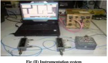
instrumentation are Pre launch communication, health monitoring, Alarm generation and operation of recovery aids in case of unhealthy conditions of vehicle, acquisition of analog parameters and digital parameters through MIL-STD-1553B bus, Stores data in NVRAM, Records important events, Online Monitoring, Retrieval of trial data. The instrumentation system is as shown below in fig (II).
Fig (II) Instrumentation system
III. DUAL INTERFACE EEPROM
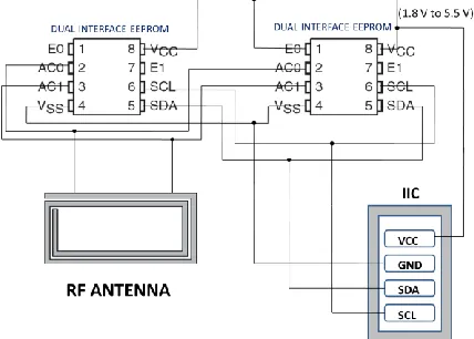
EEPROM means Electrically Erasable & Programmable Read-Only Memory. A Dual Interface EEPROM is an EEPROM with dual interface (IIC Interface & RF Interface). In the IIC mode it is a serial interface which supports 400 KHz protocol, operating with a supply voltage of -1.8v to 5.5v. In the RF mode it is a contactless interface which supports ISO 15693 & ISO1800-3 mode-1 operated at high frequency (13.56 MHz + 7 KHz carrier frequency).To Dual Interface EEPROM the modulation used is Amplitude Shift Keying (ASK) .The received ASK wave is 10% or 100% modulated with a data rate of 1.6 Kbits using the 1/256 pulse position coding & 26 Kbits using the ¼ pulse position coding. From the Dual Interface EEPROM the data is generated by Load modulation using Manchester coding with 423 KHz and 484 KHz subcarriers in low (6.6 Kbit/s) or high (26kbit/s) data rate mode. It is provided with password protection for privacy of data. In the IIC mode the memory is accessed in byte or pages (4bytes).In the RF mode the memory is accessed in blocks (1block = 4bytes). The pin diagram of the dual interface EEPROM is as shown in fig (III).
Fig (III) Dual Interface EEPROM
AC0, AC1 are antenna coils, SCL is the serial clock, SDA is the serial data, Vcc is the power supply, Vss is the ground and E0, E1 are the chip enable pins. It has a built in device type identifier code (1010) in accordance with the IIC bus definition. It behaves as a slave in the IIC protocol.
IV. INTER INTEGRATED CIRCUIT (IIC)
Developed by Philips Semiconductor in 1980”s. IIC devices include EEPROMs, thermal sensors, and real-time clocks. Used as a control interface to signal processing devices those have separate data interfaces, e.g. RF tuners, video decoders and encoders, and audio processors.IIC provides simple way to talk between IC’s by using a minimum number of pins. Only two bus lines are required: a serial data line (SDA) and a serial clock line (SCL). Each device connected to the bus is software addressable by a unique address and simple master/slave relationships exist at all times; masters can operate as master-transmitters or as master-receivers. Serial, 8-bit oriented, bi-directional data transfers can be made at up to 100 Kbit/s in the Standard-mode, up to 400 Kbit/s in the Fast-Standard-mode, or up to 3.4 Mbit/s in the High-speed mode. The number of ICs that can be connected to the same bus segment is limited only by the maximum bus capacitive loading of 400 pF.
In the fig (IV)
Start – high-to-low transition of the SDA line while SCL line is high
Stop – low-to-high transition of the SDA line while SCL line is high
Ack – receiver pulls SDA low while transmitter allows it to float high
[image:2.612.384.504.134.253.2] [image:2.612.65.272.294.416.2]International Journal of Emerging Technology and Advanced Engineering
Website: www.ijetae.com (ISSN 2250-2459, ISO 9001:2008 Certified Journal, Volume 3, Issue 9, September 2013)
230
Fig (IV) IIC Communication start & stop
V. DESIGN OF DUAL INTERFACE EEPROM TAG
Depending upon the memory requirement EEPROM is selected. A tag with Antenna, Dual interface EEPROM & IIC interface is designed. Dual interface EEPROM is an 8pin IC. The AC0, AC1 of IC are connected to the antenna board. The SCL, SDA, VCC & VDD are connected to the IIC interface.E0, E1 are left open, then the E0,E1 bits in the device select code will be (0,0). When more than one EEPROM are used depending on the connections on the board the E0, E1 values will be chosen. If these pins are connected to VCC or VDD the corresponding bits are taken as 1, 0 respectively. If the EEPROM is accessed via IIC, it can be operated from a Vcc power supply. If it is accessed via RF reader, it can be operated by the power received from the electromagnetic wave. Therefore the designed tag works in IIC mode (wired mode) with power supply and in RF mode (wireless mode) without power supply. The circuit design is as shown in fig (V).
Fig (V) Design of Dual InterfaceEEPROM Tag
VI. RF READER/WRITER
RF Reader/writer can be of various types like handheld RF reader, pc based RF reader, and mobile phone with NFC (near field communication) feature. For a hand held reader it should be capable of reading the high frequency 13.56Mhz.By using the various RF commands we can perform both read and write operations. In the case of a pc based RFreader we have to send the commands from the pc through the RF reader/writer. In the case of a mobile phone with NFC feature we have to develop an android application for performing both read and write operations. By using any of the above devices we can perform both read and write operations.
Here we developed PC based RF reader/Writer for
interfacing with Dual
Interface EEPROM
.Fig (VI) RF Reader accessing Dual InterfaceEEPROM
VII. EVALUATION OF DUAL INTERFACE EEPROM
During the development stage the performance evaluation of the system is essential. So the designed Dual
Interface EEPROM tag has been evaluated using a
[image:3.612.65.273.143.288.2] [image:3.612.349.553.322.461.2] [image:3.612.59.273.522.675.2]International Journal of Emerging Technology and Advanced Engineering
Website: www.ijetae.com (ISSN 2250-2459, ISO 9001:2008 Certified Journal, Volume 3, Issue 9, September 2013)
231
Fig (VII) Evaluation of Dual Interface EEPROM in IIC Mode
VIII. “PCBASED RFREADER/WRITER”
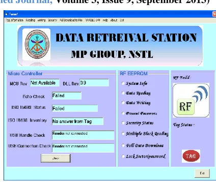
We have identified a pc based RF reader/writer “DEMO-CR95HF-A”.It consists of a microcontroller, CR95HF Transceiver IC, 47x34 mm Loop antenna. It has USB-B connector for powering on the RF reader/writer board and exchange of commands between RF reader/writer board and pc. The main function of the microcontroller is to convert the commands from USB Interface to Serial Peripheral Interface. It has been provided with JTAG connector for programming/debugging the microcontroller.
In the case of a pc based RF reader we have to send the commands from the pc through the RF reader/writer. To send the commands there is a need of development of GUI (Graphical User Interface) for the RF reader/writer. We have developed a GUI using Visual Basic through which we can access the RF reader/writer. The GUI is developed with many options like Initial check, Read single block, Read Multiple blocks, System Info, Security Status, Password locking, full data download and saving to text document and Graphical Display of RF status and presence/absence of the tag. The green color tag display represents presence of tag while red color tag display represents absence of the tag. The application requires CR95HF.dll file to be present in the system. The initial check gives the microcontroller revision, DLL version, Echo, ISO 15693 Status, ISO 15693 Inventory, USB Handle Check, and USB Connection Check. The GUI is also having the menu bar with all the functionalities. The developed Graphical User Interface (GUI) is as shown in fig (VIII).
Fig (VIII) Graphical User Interface
IX. DOWNLOADING DATA
The following are the steps to download the recorded data from the Instrumentation system/Dual Interface EEPROM.
Step1: Connect the RF Reader/writer to the pc.
Step2: Open the Data Retrieval Station application.
Step3: Click on the check button. It displays the
following information as shown in Table 1.
Step4: Select system info option. It displays the
following information about the tag as shown in Table 2.
Step5: Select Security Status option. It displays security
[image:4.612.342.554.125.304.2]status of 64 sectors.
TABLE I Initial check Parameters
Parameter RF Reader/writer connected RF reader/writer not connected
MCU Rev Revision of
microcontroller Not Available
DLL Rev Present DLL version(0.9) Present DLL version(0.9)
Echo Check Success Failed
ISO 15693 Status Selected Failed
ISO 15693 Inventory
UID of Dual Interface
EEPROM Tag not present
USB handle
check Reader Connected Reader not Connected
USB connection check
Reader Connected &
[image:4.612.59.279.136.290.2] [image:4.612.324.563.503.703.2]International Journal of Emerging Technology and Advanced Engineering
Website: www.ijetae.com (ISSN 2250-2459, ISO 9001:2008 Certified Journal, Volume 3, Issue 9, September 2013)
232
Step6: Depending upon the Security Status of 64 sectors.
Select Present Password option and enter the password to unlock the locked sectors.
Step7: Select Full Data Download option & click on
[image:5.612.336.548.129.304.2]Download button. It displays the entire downloaded data on screen and also saves the downloaded data to a text document.
TABLE III Tag Information
Tag Information
UID Displays 64 bit unique identifier of Dual Interface EEPROM
DSFID Displays data storage format identifier of Dual Interface EEPROM
AFI Displays Application Family Identifier of Dual Interface EEPROM
Block Size Displays Block size in Dual Interface EEPROM
Memory Size
Displays Memory Size of Dual Interface EEPROM
IIC Reference
Displays IIC Reference of Dual Interface EEPROM
X. RESULTS
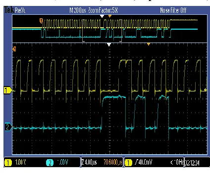
The following are the results obtained while performing the read and write operations from EEPROM through IIC. The write operation result observed on the scope is shown in the fig (IX). In the fig (IX) the Yellow colour line indicates the clock (SCL) and Blue colour indicates the data line (SDA). We can observe that the SDA line shifts from high to low when SCL is high indicating start condition of IIC. Similarly we can observe that the SDA line shifts from low to high when SCL is high indicating stop condition of IIC. We can also observe transmission of data in SDA (Ack in between start and stop)
Fig (IX) Write Operation through IIC
The read operation result observed on the scope is shown in the fig (X). In the fig (X) the Yellow colour line indicates the clock (SCL) and Blue colour indicates the data line (SDA). We can observe that the SDA line shifts from high to low when SCL is high indicating start condition of IIC. Similarly we can observe that the SDA line shifts from low to high when SCL is high indicating stop condition of IIC. We can also observe transmission of data in SDA (Ack in between start and stop)
[image:5.612.57.282.232.440.2] [image:5.612.338.549.428.578.2]International Journal of Emerging Technology and Advanced Engineering
Website: www.ijetae.com (ISSN 2250-2459, ISO 9001:2008 Certified Journal, Volume 3, Issue 9, September 2013)
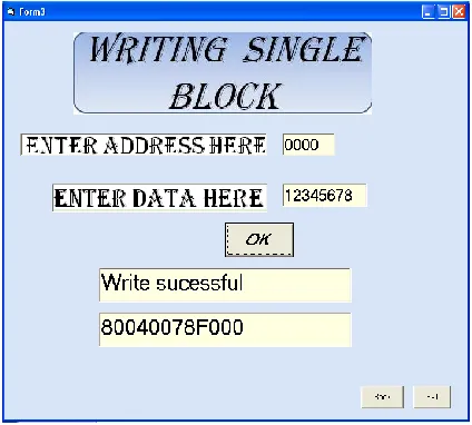
233 The following are the results obtained while performing the read and write operations from Dual Interface EEPROM through RF READER/WRITER. The results are observed on pc through GUI created by using Visual Basic. The write operation result observed on the GUI is as shown in the fig (XI) when the data “12345678” written to address location “0000h”. The read operation result observed on the GUI is as shown in the fig (XII) when the address “0000h” is read
from theDual InterfaceEEPROM .we can observe both the
written data and read data from “0000h” address location are same.
Fig (XI) Write Operation through RF Reader/Writer
Fig (XII) Read Operation through RF Reader/Writer
The following are the results obtained while performing the read operation of entire data from Dual Interface EEPROM through RF READER/WRITER and saving to the text file. The results are observed on pc through GUI created by using Visual Basic and text document. The full data download operation result observed on the GUI is as shown in the fig (XIII) when entire data is downloaded and saved to the text file. The fig (XIV) shows the view of saved text file.
Fig (XIII) Full Data Download Operation through RF Reader/Writer
Fig (XIV) View of saved Text File of Dual Interface EEPROM data
[image:6.612.329.559.246.423.2] [image:6.612.62.274.267.458.2] [image:6.612.331.554.441.617.2] [image:6.612.60.277.481.681.2]International Journal of Emerging Technology and Advanced Engineering
Website: www.ijetae.com (ISSN 2250-2459, ISO 9001:2008 Certified Journal, Volume 3, Issue 9, September 2013)
234
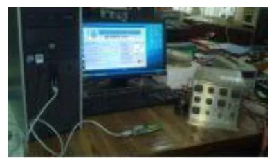
Fig (XV) Data Retrieval Station along with the Instrumentation System
XI. CONCLUSION
Therefore to assess the performance of the underwater vehicle, data recorded by instrumentation system can be retrieved without power ON instrumentation system or any other system of vehicle. By using this data retrieval station for Instrumentation System we can download data without power on the instrumentation system. This is helpful in knowing the proper cause of failure in case vehicle failure diagnosis without powering on any system of vehicle. Further during testing/preparation of Instrumentation system, we can read and write all the critical data using “portable RF Reader/Writer” wirelessly.
REFERENCES
[1] Guillermo N.Costa, Alfredo Arnaud,” A low frequency RFID temperature data logger”. IEEE-conference, 2011.
[2] U. Karthaus, M. Fischer, Fully integrated passive UHF RFID transponder IC with 16.7 W minimum RF input power, IEEE Journal of Solid-State Circuits 38 (2003) 1602–1608.
[3] R.Kuchtza, P.Stefan, Z.Barton, R.Vrba and M.Sveda,” Wireless Temperature Data Logger”, IEEE-conference, Sept 2005.
[4] Wei Dai, Shuo Zhou, Guangjun Luo, Zongxing Chen, Ling Xie,” Analyze on Mobile Payment Based on RFID”, Procedia Environmental Sciences, ESIAT 2011.
[5] Matt Ward , Department of Design , Goldsmiths College, University of London, Rob van Kranenburg Resonance Design/ Virtueel Platform,” RFID: Frequency, standards , adoption and innovation”, JISC Technology and Standards Watch, May 2006.
[6] The State of RFID Implementation and Its Policy Implications: An IEEE-USA White Paper.
[7] http://www.st.com/st-web-ui/static/active/en/resource/technical/ document/datasheet/CD00217247.pdf
[8] http://www.st.com/st-web-ui/static/active/en/resource/technical /document/application_note/CD00280653.pdf
[9] http://www.st.com/st-web-ui/static/active/en/
st_prod_software_internet/resource/technical/software/demo_and_ex ample/stsw-m24lr005.zip
[image:7.612.74.272.130.244.2]