Volume 02, No. 4, April 2016
P
age
156
Effective Method for Generating Minimal Test Cases Using
Graph Theoryoptimization
P. Velmurugan*, Rajendra Prasad Mahapatra**, & Jitendra Kumar***,
*Department of Computer Science & Engineering,Assistant Professor, SRM University, NCR Campus,Modinagar, Ghaziabad, Uttar Pradesh
**Department of Computer Science & Engineering,Professor, SRM University, NCR Campus, Modinagar, Ghaziabad, Uttar Pradesh
***Department of Computer Science & Engineering,M.Tech, SRM University, NCR Campus,Modinagar, Ghaziabad, Uttar Pradesh
ABSTRACT
The main objective for regression testing is to ensure that the changed system works according to specification, while optimizing the no of test cases by making it efficient and effective. So far, a number of techniques have been proposed. One such approach uses Steiner Tree algorithm to generate a minimal test set to check functionality.. The limitations of this approach are: a loop is unfolded twice to contain the size of the graph, a fork join construct which represents concurrent activity is considered as a single node. This paper aims to resolve these issues to further improve the efficiency and generating test cases using sequence diagram and activity diagram,Sequence-Activity Graph is constructed from two diagrams Sequence Diagram and Activity Diagram.Then a Sequence-Activity Graph is constructed from these two diagrams. Then that graph is traversed to generate test cases which are able to minimize test case explosion.
Keywords- Minimal Test Case Generation, Graph Theory Optimization, Regression Testing.
INTRODUCTION
Volume 02, No. 4, April 2016
P
age
157
process software testing can be implemented at any time. But the testing is implemented after all the requirements are defined and the coding process is over. But Code based testing having certain disadvantages which are as follows:
• Code based testing is not capable of extracting the behavioral aspects of the system. • Code based software testing is not suitable for component based software development, because the source code may not be available to the developer.
An alternative approach is to generate test cases from the models which represent the software. It has the specific feature that the testing techniques can be applied throughout the development process depending on the requirement specification and design models. Another advantage of model based testing is that the generated test data is independent of any particular implementation of design. The model based testing reduces the testing time and effort.
Therefore now the researchers have used the analysis and design models like Unified Modeling Language for test case generation. UML models are very popular because UML is a solution of standardization and utilization of design methodologies. Another advantage of UML models is that it provide different diagram for representing different view of system models.
Concurrent computing is a property of systems in which several computations are executing simultaneously and also interacting with each other. Testing a concurrent system is a very difficult task because this type of system can reveal different responses depending upon different concurrency condition.
A concurrent system may be implemented via processes and/or threads. Due to concurrency a major problem arises known as explosion of test case because of the possibility for arbitrary interference of concurrent threads. These threads are executing relatively independently. However, since they are acting towards some goal, they must need to communicate and coordinate. So, issues arise while testing the concurrent system. In case of object oriented system objects interact with each other to accomplish task. While objects are interacting with each other there may be arbitrary interference of concurrent threads. Each thread may have more than one activity which may be dependent on each other; that may be inter thread dependency or intra thread dependency. Due to these problems there issues like Communication deadlock and synchronization may arise.
In this paper, we propose an approach for generating test cases using combinational Graph Theory Graph. In our approach we have taken the combination of sequence and activity diagram which are then traversed to generate the optimized test suite.
RELATED WORK
Volume 02, No. 4, April 2016
P
age
158
and other for false condition. Then the graph is traversed using graph traversal algorithms i.e. BFS and DFS. By applying All Sequence Message Path Criterion the author has find out all the possible message paths from the starting node to the end node. After traversal some test case are generated which are able to detect the operational faults as well as interaction faults.
K. P. Jayant[3] proposed a method to generate test cases from Activity Diagram (AD). The author first convert the Activity Diagram into an intermediate format known as called I/O explicit Activity Diagram (IOAD). In this diagram the author has suppressed the non-external input and output. He has only represented the non-external input and output as the internal activities are less important than the external activities to avoid test case explosion. Then an directed graph is being constructed using the basic path coverage criterion. After that the graph is traversed using DFS algorithm. Finally a set of basic paths are derived to generate the test cases.
Bipin Pandey[4] proposed a method to generate the Test Sequences from UML 2.0 Sequence Diagram. In this approach the author first find out the different types of relationship like indirect message dependency, direct message dependency, simple indirect message dependency, simple direct message dependency that exists between the messages. Depending on the relationship different message sequences are generated and a graph is constructed known as Sequence Dependency Graph (SDG).Here each node in the SDG represent a message or a set of messages. Here the author associate node with the message number. Finally the SDG is traversed to generate the test cases.
Md Azzaharuddin[5] proposed a method to generate test cases from UML 2.0 Sequence Diagram. To represent the complex scenarios she has used the Combined Fragment (CF). By applying some mapping rule In this approach first the Sequence Diagram (SD) is transformed into an intermediate form called Concurrent Composite Graph (CCG) to represent different scenario and their flow. Then the CCG is traversed using Message Sequence Paths Criteria (MSPC) to generate the test cases. The test cases are useful for detecting scenario, interaction as well as operational faults.
Bernhard K. [6] proposed a method for generating test cases from combination of UML models i.e. Sequence diagram (SD) and Use case Diagram (UD). In this approach first of all SD is converted into Sequence Diagram Graph (SDG). Then the UD is converted into Use case Diagram Graph ( UDG.)In the UDG each actor is represented as node in the graph and assigns some edges between the nodes. Then the SDG and the UDG are combined to form a graph called as System Testing Graph (STG). Then STG is being traversed to generate the test cases.
Volume 02, No. 4, April 2016
P
age
159
Quershi T. [8] proposed an approach to generate test cases from UML Activity Diagram(AD). Then the AD is converted into an intermediate format known as Activity Graph (AG) by applying some transformation rules. The AG is traversed using BFS and DFS algo. BFS algorithm is used traverse all the concurrent activities and the rest are traversed by using DFS. Here the author uses the Activity Path Coverage Criterion to generate different Activity Paths.
Shukla.Upasana[9] proposes a method for generating test cases from sub activity diagram to compound activity diagram in a hierarchical manner. They introduce the idea of this method by taking the thought of functional decomposition, bottom-up integration testing strategy and round-robin strategy.
Emanuela G Cartaxo[10] proposed a method to generate test cases from combinational UML models such as Sequence Diagram (SD) and Activity Diagram (AD). In her approach AD is converted into an intermediate format known as Activity Graph (AG). After that test sequences are generated from AG by applying Activity Path Coverage Criteria. Then SD is converted into Sequence Graph (SG) and the test sequences are generated by applying All Message Path Coverage Criterion. For having better coverage and high fault detection capability the author constructed a Activity Sequence Graph (ASG) which has the combine features of AG and SG. Finally the ASG is traversed to generate the test cases.
BASIC CONCEPTS
A. Sequence Diagram
The Sequence Diagram is a type of interaction diagram that is used for dynamic modeling which focuses on identifying the behaviour within the system. It represents object interaction arranged in a time sequence. These diagrams are used to represent or model the flow of messages, events and actions between the objects or components of a system. Sequence diagrams are typically used to describe the object-oriented system. It describes the objects and classes involved in the scenario and also the sequence of messages exchanged between the objects to carry out the functionality of the scenario.
B. Activity Diagram
An UML Activity Diagram is suitable for representing concurrent interaction among multiple threads. An Activity Diagram describes how multiple objects collaborate to do a specific set of operation. The basic elements of Activity Diagram are activity and transition. Activity is used as a state for doing something and the transition is represented as a directed line which connects different activities. A transition can be message flow, object flow or control flow. Activity Diagram is used for both conditional and parallel behaviour. Conditional behaviour can be denoted as a branch and a merge, and parallel behaviour is denoted by a fork and a join.
C. Concurrent System
Volume 02, No. 4, April 2016
P
age
160
D. Concurrent System
In a Concurrent System different programs or threads are represented as collections of interacting computational processes that may be executed in parallel. The execution of threads begins from fork node and ends at join node. The main limitations in designing concurrent program to ensure the correct sequencing of the interactions or communications between different computational processes and coordinate the access to shared resources.
PROPOSED METHODOLOGY
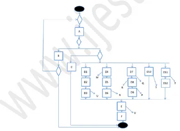
We have proposed a methodology whose model diagram is shown in Fig. 1. The model has been proposed for generating test cases for concurrent system. In our approach we have presented an approach to generate test cases for concurrent system using combinational UML models. Here we have used the combination of Sequence diagram and Activity diagram. In a concurrent system several computations are processed simultaneously and also potentially interacting with each other.
In our approach we have taken a sequence diagram and an activity diagram. From these two diagrams we have constructed a graph named as Sequence-Activity graph (SAG) by using an algorithm named as sequence-activity graph. Then the SAG is traversed using graph traversal algorithm i.e. BFS and DFS to generate test cases.
Figure1.A Frame work of our proposed methodology
The resultant shows that the generated test cases are being capable of addressing the issue like test case explosion as we are dealing with concurrent system.
Volume 02, No. 4, April 2016
P
age
161
concurrent system. Software testing is especially very much difficult when a system contains concurrently executing objects.
For this we have taken the activity diagram as the activity diagram is very much suitable for concurrent system as the activity diagram is capable of showing the parallel execution of different activities in a concurrent system.
Testing a concurrent system is a difficult task due to the arbitrary interference of different threads. Each thread may have more than one activity. Activities present in same thread maintain partial order relationship which shows dependency called as Intra thread dependency. Also activities of different thread may be dependent on each other called as Inter thread dependency.
Due to these types of dependency some critical situation arises during message passing which leads to a communication deadlock and also it causes test case explosion. So our objective is to minimize the test case explosion while generating the test cases.
Our approach consists of the following steps:
1) Construction of a Sequence Diagram (SD) and an Activity Diagram (AD).
2) Maintaining a Sequence Table (ST) with different schema as Source object(SC), Destination object(DO), Message ID(MI) and Message Content(MC) by taking the information from SD.
3) Then construction of Sequence-Activity Graph (SAG) by combining the features from SD and AD.
4) Finally traversal of SAG to generate test cases.
Example of Sequence diagram and Activity diagram
In this section we have presented the dummy examples of sequence and activity diagrams. Here we have used the Activity Diagram and Sequence diagram due to the following reasons:
Activity diagram is suitable for representing the concurrent activities as there is no state explosion of objects a in state chart diagram. Activity diagram shows the sequence of activity flows and also it represents parallel activities taken place in fork and join node.
Volume 02, No. 4, April 2016
P
age
162
Figure 2. Sequence Diagram
U, M, R, N, Q, P, S, T are different objects of Sequence Diagram shown in Fig 2 . M1, M2 , M3,M4 and M5 are different messages that are flows between the objects.
The activity diagram represents the sequence of activity taken place. In this Activity diagram the Inter and Intra thread dependency are present. In above diagram different objects are like U,M,N,P,T,R,S,V are created after or before completion of different activities.
Technique for constructing Sequence Table (ST)
Volume 02, No. 4, April 2016
P
age
163
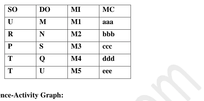
Table I. Sequence Table
SO DO MI MC
U M M1 aaa
R N M2 bbb
P S M3 ccc
T Q M4 ddd
T U M5 eee
Construction of Sequence-Activity Graph:
In this approach we propose a technique for generating SAG by combining both the features of Sequence diagram and Activity diagram. Whenever a transition is there we then take the two nodes in SAG and assign an edge between them. The nodes shown in the graph may be the Object node or Activity node. More no of threads are present in the Activity diagram in concurrent system. The activities present in different threads may be dependent on each other which are called as Inter thread dependency. The objects are created after activities are being taken place and communicating with each other by passing message among them.
Node Representation of SAG
To represent a node in the graph two types of lists are required i.e. node list and edge list.
Node List
Figure 3. Node Structure
Here the status field shows whether the node is a object node or activity node. 0 means object node and 1 means the node is an activity node. Node ID represents the unique ID of the node and the third field represents the address of the next node. and address of next edge shows the next adjacent node.
Edge List
Figure 4. Edge Structure
Here the Dependency Bit field describes the edge connecting to the nodes are Intra thread or Inter thread. I is denoted as Inter thread and O is denoted as intra threaddependency. Link field denotes the address of the next adjacent node of the Edge structure.
Traversal of Sequence Activity Graph
Volume 02, No. 4, April 2016
P
age
164
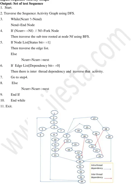
Algorithm: Test Cases from Sequence Activity Diagram (TCSAG)
Input: Sequence-Activity Graph Output: Set of test Sequence
1. Start.
2. Traverse the Sequence Activity Graph using DFS.
3. While(Ncurr !=Nend)
Nend=End Node
4. If (Ncurr= =Nf) // Nf=Fork Node
Then traverse the sub tree rooted at node Nf using BFS.
5. If Node List[Status bit= =1]
Then traverse the edge list.
Else
Ncurr=Ncurr->next
6. If Edge List[Dependency bit= =0]
Then there is inter thread dependency and traverse that activity.
7. Go to step4.
8. Else
Ncurr=Ncurr->next
9. End If
10. End while
11. Exit.
Volume 02, No. 4, April 2016
P
age
165
After the construction of Sequence-Activity Graph(SAG) we have traversed the SAG using Graph traversal algorithm. While traversing the nodes whenever a fork node is encountered, we will apply BFS (Breadth first Search) algorithm and for the rest nodes we have applied DFS (Depth First Search) algorithm in order to generate test cases. In this approach we have used the Activity path coverage criteria to generate test cases. After traversing the graph some test sequences are generated which are given below.
T1=1-2-3-4-5-6-2-3-4-5-6-34 T2=1-2-3-4-7-8-34
T3=1-2-3-4-7-9-10-11-14-12-13-15-16-17-18-19-20-21-22-23-26-24-25-27-28-29-30-31-32-33-34
CONCLUSION
In this paper we have proposed an approach for generating test cases using Graph theory optimization. In our approach we have taken the combination of sequence and activity diagram to construct a graph known as Sequence-Activity Graph(SAG).The partial ordering relationship that exists due to inter thread and intra thread communication is also included in the approach. The SAG is then traversed to generate the optimized test suite which minimizes the test case explosion.
FUTURE WORK
Asuitable optimization technique like Genetic Algorithm or Particle Swarm Optimization can be used to further reduce thevolume of test data to be generated.
REFERENCES
i. An Approach for Generating Minimal Test Cases for Regression Testing , Sapna P G, ArunkumarBalakrishnanProcedia Computer Science 47 pages188 – 196 ( 2015 )
ii. Paolo Arcaini, Angelo Gargantini, and ElviniaRiccobene.An abstraction technique for testing decomposable systems by model checking. In Tests and Proofs, volume 8570 of LNCS, pages 36–52. Springer, 2014.
iii. K. P. Jayant, and RanuGarg, “An Approach of software design testing Based on UML Diagrams”, IJARCSSE, Feb 2014.
iv. BipinPandey, and Rituraj Jain “Importance of Unified Modeling Language for Test Case Generation in software Testing”, IJCTA, April 2014
v. MdAzzaharuddinAli, Kashimshaik, and ShreyanshKumar, “Test Case Generation using UML state diagram and OCL Expression”, in IJCA., June 2014
Volume 02, No. 4, April 2016
P
age
166
vii. Gaurav. Sahni,Kestina. Rai, Software Testing Techniques for Test Case Generation, International Journal of Advanced Research in Computer Science and Software Engineering, Vol . 3, Issue 9, ISSN;2277 128x, 2013.
viii. QuershiT. Imran Ali, NadeemAamer, GUI Testing Techniques:A Survey, International Journal of Future Computer and Communications, Vol. 2, No. 2103.
ix. Shukla. Upasana, Bharti. A. K, Gupta. D. N, Integration Testing of Object Oriented Component Using Program Slicing in the Detection of Equivalence Mutants, International Journal of Advanced Research in Computer Science and Software Engineering,Vol. 3,Issue 1,ISSN:2277 128X, 2013..
x. Emanuela G Cartaxo, Francisco G. O., Neto,Patriciaand D. L. Machado “Test Case Generation by means of UML sequence Diagrams and Labeled Transition Systems”, UFCG, March 2013
xi. Jayaprakash Krishnan, GunasekarSubramani and Sapna P G.. Article: Development of a Change Impact Model for Regression Testing using UML Diagrams. IJCA Proceedings on International Conference on Distributed Computing and Internet Technology 2014 ICDCIT-2014:31-36, December 2013.
xii. Mishra. Manish, Mishra.Shalini, Porawal.Robins, Basic Principle for Test Case Generation Automatically, VSRD International Journal of Computer Science and Information Technology, VSRD-IJCSIT, Vol. 2(9), pg. 772-781, 2012.
xiii. Swati Tahiliani, and PallaviPandit, “A Survey of UML Based approaches to testing”, IJCER, Sept 2012
xiv. A.V. K. Shanthi, and G. MahanKumar, “A Heuristic approach for Automated Test Case Generation from Sequence Diagram using Tabu Search Algorithm”, EJS, Sept 2012