Volume 2, Issue 5, 2015
66 Available online at www.ijiere.com
International Journal of Innovative and Emerging
Research in Engineering
e-ISSN: 2394 - 3343 p-ISSN: 2394 - 5494
Automatic Sorting Machine Using Conveyor Belt
Sanjay Prakash Dabade
a, Rohan Prakash Chumble
ba P.G. Student, Department of Mechanical Engineering, Walchand College of Engineering, Sangli, India b Assistant Professor, Department of Mechanical Engineering, Walchand College of Engineering, Sangli, India
ABSTRACT:
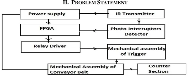
Design the automated sorting machine using conveyor belt to need the manufacturing industry in many fields is a very complex process. The system needs to satisfy industry requisition. This is an industrial automation based application. It shows the concept of normal conveyor belt, but with some intelligence. We can also call it as intelligent conveyor belt, as it has also ability to sort the object of different sizes. This helps to avoid size malfunctioning in production machines. In the core of the project, we are using field programmable gate array (FPGA). The FPGA is used in PLC and controls the relay and drives relay according to output of photo interrupter. IR rays in photodiode are used for detection. The objects of different sizes are passed through the sensors and the object having specified size is sorted. The belt is driven by drive circuit which is controlled by drive controller. By developing such sorting system the production rate of the manufacturing industry has been increased since these sorting systems replaced the human resources. Also the accidents in manufacturing industry can be prevented because the uses of operator in manufacturing floor had been reduced.
Keywords: Automatic, Sorting, Conveyor Belt, Component, FPGA.
I. INTRODUCTION
Sorting is very important in any type of industry such as manufacturing industry to improve the efficiency of manufacturing processes. The main task performed here is to sort the products manufactured in the company [1]. The purpose of this project is to save the time for inspection and to reduce the efforts of the workers in material handling. An automatic sorting machine has main task of sorting components according to the sizes. This also consist of conveyor belt, which reduces the efforts of material handling. Also both processes take place simultaneously viz material handling and inspection.
A sorting machine is more practical and economical method of automation, which transfers material from one point to another. The design is quite simple and of flexible use, means only conveyor belt can be used for material handling.
Conveyor:-
A conveyor belt consists of two or more pulleys, with a continuous loop of material which rotate over them. One or both of the pulleys are powered, moving the belt and material on the belt forward. There are two main industrial classes of belt conveyors; those in general material handling such as those moving boxes along inside a factory and bulk material handling such as those used to transport industrial and agricultural materials, such as grain, coal, ores etc.
II. PROBLEM STATEMENT
Volume 2, Issue 5, 2015
67 The problem statement for the project is to create the electronic material handling system which can be used to reduce the efforts of workers as well as to reduce the time spent in inspection of the components, during their manufacturing. It also reduces the efforts in transferring the components manufactured to anther workstation. The most apparent reasons that are associated in installing of automatic system in industry are,
i. Saving Man Power
ii. Improved Quality and Efficiency iii. Increase consistency and Flexibility [2]
The block diagram for the automatic sorting using the conveyor belt is shown below.
III. CONSTRUCTION OF UNIT
Detailed procedure of the fabrication of the project and use of different machines: i. Gas Cutting:-
The Scrap material which was an angle used for the frame is firstly cut into desired length. As the material was in welded condition, we have used the gas cutting method for ease of the cutting.
ii. Band saw cutting;-
Now we are having all the scrap material as per our requirement in the design. After referring the drawing the detailed dimensioning for the material available is made and the available scrap material is cut using the band saw cutting machine. This is semiautomatic machine so the mounting is done manually by us and cutting taken place automatically.
iii. Preparation of Frame:-
The angles and C channels are arranged as per the drawing. The frame is now welded using oxy-fuel welding is done, now the frame is ready.
iv. Fabrication of the shafts:-
The available bearing and required rotation, power requirement etc gave overall structure of the shaft. We have prepared the temporary drawing of the shaft and then we have fabricated the shaft on the lathe machine. v. Fabrication of the drum pulleys:
According to the frame structure and drawing, we have the drum pulleys. For the locking of the shaft the appropriate plates are also fabricated on the lathe. Firstly these plates are bored as per the shaft diameter. These plates are then welded to the drum with the shaft inserted through the drum.
vi. Preparation of sub-frame:-
After the preparation of the frame, we have prepared the sub-frame for the drive unit. This frame is used for drive unit.
vii. Preparation of the blocks with provision of the bearing;-
After the preparation of the sub-frame, the square blocks are brought and they are bored for the bearing size. Then these square blocks are welded to the frame. The shafts are inserted in between the blocks and bearing are fitted using press fit.
viii. Adjustments for the tension for the belt:-
For the adjustment of the tension of the belt, the appropriate sized nut bolt are fitted which gives the desired tension adjustments.
ix. Preparation of the drive unit:-
Now the pulleys are brought as per the drawing, and after the fitting pulleys to shafts, the measurements for the V-Belts are taken and then they are adjusted over the pulleys.
x. Building a conveyor belt:-
Now the main conveyor belt is built on the drums, then required tension is provided using adjustments of the nut-bolt assembly.
Volume 2, Issue 5, 2015
68
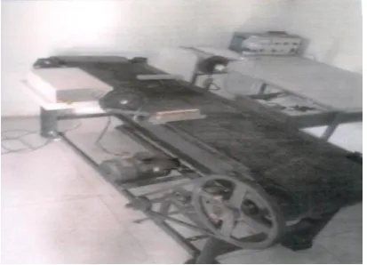
Figure 2. Automatic sorting machine using conveyor belt
IV. CONSTRUCTION DETAILS
a. The unit consists of the conveyor belt which is driven by electric motor.
b. The conveyor belt is mounted on the mild steel frame which is fabricated using the angles and channels. c. At the two ends of the frame, using journal bearing, two drum pulleys are bolted to the frame over which
the belt runs.
d. For the drive, the electric motor is used. For the speed reduction, the sub frame is fabricated which is having intermediate shafts.
e. This speed reduction system contains two stage reduction using belt pulley assemblies.
f. For the purpose of idling, the sheet metal is used which also acts as scrubber to reduce the dust on the belt. g. Then sensors are located on the conveyor belt.
h. For the wiring and electronic assembly, the separate sheet metal block bolted to frame. i. For the pushing and sorting purpose, the pushing mechanisms are mounted on the frame. j. These mechanism consist of simple piston crank mechanism.
k. After sorting, the provision is made for automatic switching off the conveyor belt.
V. CONSTRUCTION DETAILS
a) The unit consists of the conveyor belt which is driven by electric motor.
b) The conveyor belt is mounted on the mild steel frame which is fabricated using the angles and channels. c) At the two ends of the frame, using journal bearing, two drum pulleys are bolted to the frame over which
the belt runs.
d) For the drive, the electric motor is used. For the speed reduction, the sub frame is fabricated which is having intermediate shafts.
e) This speed reduction system contains two stage reduction using belt pulley assemblies.
f) For the purpose of idling, the sheet metal is used which also acts as scrubber to reduce the dust on the belt. g) Then sensors are located on the conveyor belt.
h) For the wiring and electronic assembly, the separate sheet metal block bolted to frame. i) For the pushing and sorting purpose, the pushing mechanisms are mounted on the frame. j) These mechanism consist of simple piston crank mechanism.
k) After sorting, the provision is made for automatic switching off the conveyor belt.
VI. DESIGN OF COMPONENT
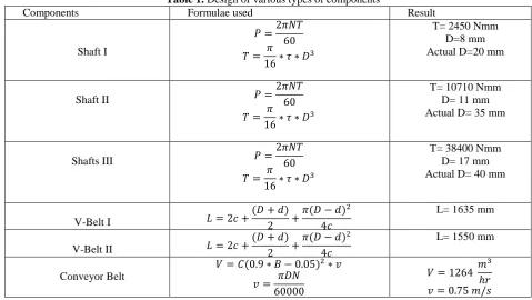
The following table shows the design of various types of components and actual value of the component used to design the automatic sorting machine using conveyor belt [3] [4] [5].
Table 1. Design of various types of components
Components Formulae used Result
Shaft I
𝑃 =2𝜋𝑁𝑇
60
𝑇 = 𝜋
16∗ 𝜏 ∗ 𝐷
3
T= 2450 Nmm D=8 mm Actual D=20 mm
Shaft II 𝑃 =
2𝜋𝑁𝑇 60
𝑇 = 𝜋
16∗ 𝜏 ∗ 𝐷
3
T= 10710 Nmm D= 11 mm Actual D= 35 mm
Shafts III 𝑃 =
2𝜋𝑁𝑇 60
𝑇 = 𝜋
16∗ 𝜏 ∗ 𝐷
3
T= 38400 Nmm D= 17 mm Actual D= 40 mm
V-Belt I 𝐿 = 2𝑐 +
(𝐷 + 𝑑)
2 +
𝜋(𝐷 − 𝑑)2
4𝑐
L= 1635 mm
V-Belt II 𝐿 = 2𝑐 +
(𝐷 + 𝑑)
2 +
𝜋(𝐷 − 𝑑)2
4𝑐
L= 1550 mm
Conveyor Belt
𝑉 = 𝐶(0.9 ∗ 𝐵 − 0.05)2∗ 𝑣
𝑣 = 𝜋𝐷𝑁
60000
𝑉 = 1264 𝑚
3
Volume 2, Issue 5, 2015
69
Ball Bearing 𝐿10=
60𝑁𝐿10ℎ
106
𝐿10= 198000 𝑀𝑅
Bearing No. = 6405
Electric motor 𝑃 =
2𝜋𝑁𝑇 60
𝑇 = 𝜋
16∗ 𝜏 ∗ 𝐷
3
T= 0.0243 Nmm P= 0.0366 kW Actual P=.37 kW
Relays are used for
• Amplifying a digital signal, switching a large amount of power with a small operating power.
• Detecting and isolating faults on transmission and distribution lines by opening and closing circuit breakers (Protection relays).
VII. WORKING OF UNIT
1. The drive is given to the head pulley. The material is fed on to the conveyor at head pulley. 2. The product used for testing is a cubical product.
3. So now the cubical product is kept above head pulley. Now the switch which is situated at conveyor belt is made on.
4. Now the conveyor will start. The sensor which is situated just before pushing mechanism, will sense the product and the signal is sent to micro controller.
5. There the calculations will be done and the decision has taken that which type of the product is this. 6. After that, the product will be travelled to tail pulley.
7. The signal will be now given to pushing mechanism.
8. After identifying the product, the conveyor will be get automatically switched off.
9. So after stopping of the conveyor, corresponding mechanism will be get actuated as per received from the microcontroller, and the products will be get sorted.
VIII. TESTING OF UNIT
The product will be placed on the conveyor. Then the switch will be made on which will start the conveyor and the product will flow to discharge end. During its travel, sensor will sense the width of the product. The signal will be then given to microcontroller. So according to the signal the corresponding LED will glow indicating the size that is small, medium and large.
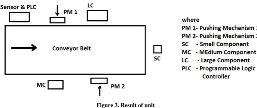
Figure 3. Result of unit
After that the pushing mechanism will be activated and large and medium products will be pushed out from the conveyor, while small product will flow over the conveyor. After sorting of the product, conveyor will automatically switch off. Fig 3 shows result of the unit such as the small component will go without any pushing mechanism to other end of the conveyor belt. The sensor and PLC will give input to pushing mechanism to activate respectively as per the size of component i.e. medium and large size of component if the size of the component is medium pushing mechanism 1 will activate and if the size is large then pushing mechanism 2 will be activated. After this activation of pushing mechanism the small, medium, and large component will go to the straight, right and left side of the machine.
IX.CONCLUSION
Volume 2, Issue 5, 2015
70 workers by reducing the time spent for material handling. The application area of this machine is very wide in industries where automation is built
X. FUTURE SCOPE
By producing such system, the scope is in the field of • Manufacturing
• Identification of suitable solution • Evaluation
• Design the proposal • Build the prototype [6].
Also we can use such system with some modification for various types of inspection such as Inspection Parameter
• Diameter, hole diameter • Height
• Thickness • Surface defect • Crack, burr • Roundness
• Minor and major diameter • Chamfer angle etc.
ACKNOWLEDGMENT
Any research is never an individual effort. It is contributory of many hearts and brains. I would like take opportunity to express my respect, deep gratitude and genuine regard to head of mechanical engineering department Prof. B.G.Gavali for giving me all guidance required for my journal apart from being constant source of Inspiration and Motivation. It was indeed privilege to have worked under him.
I express my sincere thanks to my guide Prof. Rohan P. Chumble and all the Mechanical Engineering Department Staff Member and my friends, who directly or indirectly helped me in completion this work.
Last but not the least, the backbone of my success and confidence lies solely on the blessings of my parents.
REFERENCES
[1] Zulhashikin Bin Talib, “Design and Modelling of Automated Sorting System in Manufacturing Industry Using Simlation Software,” Thesis of Universiti Teknikal Malaysia, Meleka, May 2007.
[2] Pankaj Agrawal, Ratnesh kumar Tiwari, Samardeep Banyal, Santosh Kanigicherla, Shivang Chaudhary, “Color/Metal Sensing Sorting System”, International Journal Of Engineering Research & Management Technology (IJERMT), Volume 1, Issue 2, March 2014.
[3] Apple, Material handling equipment, Ronald Press Co., 1972.
[4] Alexandrov, Material handling equipment, central books limited, 1981. [5] M.A.Alspaugh, Conveyor belt technologies, 2008.
[6] Zulhashikin Bin Talib, “Design and Modelling of Automated Sorting System in Manufacturing Industry Using Simlation Software,” Thesis of Universiti Teknikal Malaysia, Meleka, May 2007.