Volume 57, 2018, Pages 656–666
LPAR-22. 22nd International Conference on Logic for Programming, Artificial Intelligence and Reasoning
Rewriting Environment for Arithmetic Circuit Verification
Cunxi Yu
1, Atif Yasin
2, Tiankai Su
2, Alan Mishchenko
3, and Maciej Ciesielski
21 Ecole Polytechnique F´´ ed´erale de Lausanne, Switzerland;
2
University of Massachusetts, Amherst, MA, USA;{ayasin,tiankaisu,ciesiel}@umass.edu
3 University of California, Berkeley, CA, USA;[email protected]
Abstract
The paper describes a practical software tool for the verification of integer arithmetic circuits. It covers different types of integer multipliers, fused add-multiply circuits, and constant dividers - in general, circuits whose computation can be represented as a poly-nomial. The verification uses an algebraic model of the circuit and is accomplished by rewriting the polynomial of the binary encoding of the primary outputs (output signa-ture), using the polynomial models of the logic gates, into a polynomial over the primary inputs (input signature). The resulting polynomial represents arithmetic function imple-mented by the circuit and hence can be used to extract functional specification from its gate-level implementation. The rewriting uses an efficientAnd-Inverter Graph(AIG) rep-resentation to enable extraction of the essential arithmetic components of the circuit. The tool is integrated with the popular ABC system. Its efficiency is illustrated with impressive results for integer multipliers, fused add-multiply circuits, and divide-by-constant circuits. The entire verification system is offered in an open source ABC environment together with an extensive set of benchmarks.
1
Introduction
Verification of arithmetic circuits can be viewed as a special case ofcombinational equivalence checking, in which the function implemented by the circuit is checked against its functional specification. Boolean methods, such as various canonical decision diagrams and SAT, that have been used extensively in logic synthesis and optimization, are computationally too expensive for arithmetic functions as they require “bit blasting”, i.e., flattening the design to a bit-level netlist. The SAT and SMT competition results confirm that the verification of even small multipliers pose a real challenge to such solvers [15]. Similarly, the commercial tools cannot fully automatically handle full-size multipliers [17]. In general, the complexity of checking equivalence of large arithmetic circuits is too high for these methods [13][20].
The techniques that offer best solution in arithmetic circuits verification are formal meth-ods based oncomputer algebra [20][10][12][17]. In this approach, the circuit specification and its implementation are represented as polynomials in binary signal variables. The verification problem is formulated as a proof that the implementation satisfies the specification. It is accom-plished by reducing the specification modulo the implementation polynomials using theory of
specification polynomial in the ideals [12][10][17][15]. Some of the authors [10][5] use Gaussian elimination, rather than explicit polynomial division, to speed up the reduction process.
An alternative, and more effective approach to accomplish the verification proof for gate-level arithmetic circuits is based on algebraic rewriting[20][21]. It transforms the polynomial at the primary outputs (called the output signature) into a polynomial in terms of primary inputs (theinput signature) [20]. The resulting signature provides the functional specification of the circuit that can be compared with the expected specification; hence the method can also serve as function extraction. Although this approach has been successfully applied to large-scale multipliers and other arithmetic circuits, it still suffers from a potential memory explosion problem during rewriting due to the growing size of the intermediate polynomials. In particular, the method is very sensitive to the order in which rewriting is done, strongly affecting the verification performance.
The verification method and the tool presented in this paper offer an important step in finding and efficient solution to the arithmetic verification problem. The method is based on representing the circuit in a functional, rather than structural, gate-level domain, called the
And-Inverter Graph (AIG) [11], in which the algebraic rewriting is done on the AIG represen-tation of the circuit.
2
Algebraic Rewriting
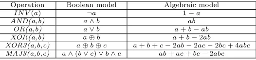
Arithmetic circuit considered in this work is a circuit that computes polynomial expressed in the input variables. The circuit is modeled as a network of interconnected bit-level components (logic gates), each with a finite set of binary inputs and a single binary output. Each gate is modeled as a unique polynomialfi[X] with binary variables X ={x1, ..., xn} and coefficients
inZ2. Such a polynomial is also referred to as apseudo-Boolean polynomial. Table 1presents
algebraic models of some of the basic Boolean operators [20].
Table 1: Boolean and algebraic models of basic logic functions.
Operation Boolean model Algebraic model
IN V(a) ¬a 1−a
AND(a,b) a∧b ab
OR(a,b) a∨b a+b−ab
XOR(a,b) a⊕b a+b−2ab
XOR3(a,b,c) a⊕b⊕c a+b+c−2ab−2ac−2bc+ 4abc
MAJ3(a,b,c) a∧(b∨c)∨b∧c ab+ac+bc−2abc
By construction, each expression evaluates to a binary value (0,1) and correctly models the logic function of a Boolean logic gate. Models for more complex AOI (And-Or-Invert) gates, used in standard cell technology, are readily obtained from these basic logic expressions. For example, algebraic model for logic gateg=a∨(b∧c) can be derived as g=a+bc−abc, etc.
Algebraic rewriting relies on relating two pseudo-Boolean polynomials, called an out-put signature and an inout-put signature. The output signature, Sigout, is the the
polyno-mial that represents the result stored as the binary encoding of the primary outputs. For example, an output signature of a signed 2’s complement arithmetic circuit with n bits, Sigout=−2n−1zn−1+P
n−2
i=0 2
iz
i. By construction, such a polynomial is unique. Similarly, the
input signature, Sigin, is the polynomial over the primary input variables that represents the
arithmetic function performed by the circuit, i.e., itsfunctional specification. For example, for ann-bit binary adder with inputs{a0,· · ·, an−1, b0,· · ·, bn−1},Sigin=Pni=0−12iai+Pni=0−12ibi.
Algebraic rewriting is the process of transforming Sigout into Siginusing algebraic models
of the internal components (logic gates) of the circuit, such as those specified by Table1. By definition, it is done in the reverse topological order: from the primary outputs (PO) to the primary inputs (PI); for this reason it is also referred to as abackward rewriting[20]. Interme-diate expression obtained during rewriting is also represented as a polynomial, referred to as as
signature, over the variables representing the internal signals of the circuit. By construction, each variable in a given signature polynomial (starting with Sigout) represents an output of
some logic gate. The rewriting transformation simply replaces that variable with the algebraic expression of the corresponding logic gate.
It has been shown that such a backward rewriting produces a unique input signature poly-nomial [20]. However, the rewriting performance strongly depends on the order in which the individual variables are rewritten. Two basic rules are used in determining the rewriting order: (1) Rewriting follows the reverse topological order; and (2) Signals that depend on common signals (fanins) are rewritten together (i.e., one immediately after the other). The first rule is obvious because of the direction in which the signature is propagated. Once a given variable (output of a gate) is rewritten, i.e., substituted by an algebraic expression of the gate inputs, it will be eliminated from the current expression and will never appear in the signature again. As a result, the final signature will be expressed in the primary inputs (PI) only. The second rule is dictated by the fact that rewriting the nodes with common fanins together maximizes the chance for potential term cancellation, hence minimizing the size of intermediate polynomials.
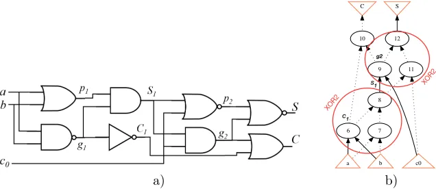
To illustrate the rewriting process consider the following example of a gate-level arithmetic circuit with inputsa, b, c0, shown in Figure1(a). The output signature of the circuit isSigin=
2C+S, determined by the weights of the two output signals dictated by the binary encoding. The goal is to determine the arithmetic function implemented by this circuit (or, equivalently to verify if it is a full adder) by rewritingSigout into an input signature (specification),Sigin.
C S
10 12
9
6
11
8
c0 7
a b
XOR2
XOR2
S1
C1
g2
a) b)
Figure 1: Gate-level arithmetic circuit (FA): a) circuit diagram; b) AIG representation
According to the rewriting algorithm [20] the optimum rewriting order is{(S, C),(p2, g2),
(S1, C1),(p1, g1)}. The signals shown in brackets are the ones that depend on common inputs;
they are to be rewritten together, i.e., one immediately after the other.
usingC andS variables.
Sigout= 2C+S
1.(S, C) : = 2(C1+g2−C1g2) + (1−(p2+g2−p2g2)) = 2C1+g2−2C1g2−p2+p2g2+ 1
2.(p2, g2) : = 2C1+S1c0−2S1C1c0−(1−(S1+c0−S1c0)) + (1−(S1+c0−S1c0))S1c0+ 1 = 2C1+S1c0−2S1C1c0+S1+c0−S1c0+S1c0−S12c0−S1c20+S
2 1c
2 0
= 2C1−2S1C1+S1+c0
3.(S1, C1) : = 2(1−g1)−2(1−g1)(p1g1)c0+p1g1+c0 = 2−2g1−2(p1g1−p1g21) +p1g1+c0 = 2−2g1+p1g1+c0
4.(p1, g1) : = 2−2(1−ab) + (a+b−ab)(1−ab) +c0
=2ab+a+b−ab−a2b−ab2+a2b2 = a+b+c0
(1)
The resulting input signature isSigin=a+b+c0, indicating that this is a full adder. During
the rewriting two types of simplifications can be observed:
• Simplification of terms with same monomials; for example, 2g2−g2=g2, in Step 1. • Lowering the term xk with degree k > 1 to x, since the signal variables are binary,
i.e., xk = x. This can be seen in Step 3 of the rewriting, shown there in bold face: (p1g1−p1g21) =p1g1−p1g1= 0. Similar simplifications appear also in steps 2 and 4.
Two modes of rewriting are possible: 1) Verification against the known specification, and 2) extracting the specification from the circuit structure. If the specification of the circuit is known, one needs to compare the computed input signature with this specification. While this can be done using canonical polynomial representations, such as TED or BMD, this comparison can be avoided altogether by rewriting thedifference between the output and input signature, Sigout−Sigin instead ofSigout. The result of such a rewriting should be zero for a correct
circuit. A non-zero result is an indication of a bug. In the case when the specification is not known, the computed input signature provides the function of the circuit (buggy or not).
In the case of a buggy circuit, the size of intermediate polynomials during rewriting may become prohibitively large, sometimes even preventing the computation from completing. This by itself can be used as a warning that the circuit is probably faulty. In general, concluding the the circuit is incorrect and identifying a bug is a challenging problem. Several attempts have been made to identify the bug(s), either by comparing the result of backward and forward rewriting [7] or by analyzing the difference between the computed input signature and the given specification [6]. With a notable exception of finite field (GF) arithmetic circuits [19] [8][14], the debugging remains an open problem.
3
AIG Rewriting
set of variables. Those nodes are essential in identifying half-adders (HA) and full-adders (FA), the basic components of an arithmetic circuit [21]. AIG rewriting then skips over the large portions of the circuitry, from the inputs to the outputs of the adders, significantly speeding up the rewriting process, as shown in Figure1(b). The algorithm is outlined in Algorithm 1 [21].
Algorithm 1Algebraic Rewriting in AIG
Input:Gate-level netlistN; Output signatureSigout
Output:Pseudo-Booleanexpression extracted by rewriting
1: G(V, E)←structural hashing ofN into AIG. 2: Detect all XOR3 and MAJ3 nodes inG(V, E). 3: P←pair(XOR3, MAJ3) nodes with common signals.
4: Topological sortG(V,E)considering each element inPas one node. 5: i= 0;Fi=Sigout
6: whilethere remain elements inV do
7: Rewrite:Fi+1←Fiby variable substitution;
8: i= i + 1
9: end while
10: returnF=Fi(to be compared withSigin)
The inputs to the algorithm are the gate-level netlistN and the output signatureSigoutand
includes four basic steps: 1) converting the gate-level implementation into AIG; 2) detecting all pairs of (XOR3, MAJ3) functions with common AIG inputs1; 3) performing topological sorting
of AIG nodes while treating the detected XOR and MAJ functions as a single element; and 4) applying algebraic rewriting from POs to PIs following the reverse topological order. As soon as the matching (XOR3, MAJ3) pairs are detected, a hybrid graphG is constructed, in which each XOR3 and MAJ3 function is considered as a single node. In the absence of XOR3, MAJ3 nodes, the two-input XOR2 and MAJ2(AND) functions are similarly detected. Algebraic rewriting is then applied to the modified graphGin a reverse topological order. The algorithm returns the extracted input signatureSigin.
In the example of Figure 1(b), the groups of nodes (6,7,8) and (9,11,12) are identified as XOR2, and nodes 6 and 9 as the matching MAJ2 (AND) functions. Subsequently, the functions at node 12 (S) and node 10 (C) are identified as XOR3 and MAJ3, respectively, sharing the same inputs,a, b, c0. At this point the entire graphG reduces to just two nodes, representing
XOR3(a, b, c) and MAJ3(a, b, c). The rewriting ofSigout= 2C+S over the two nodes is trivial,
with the nonlinear monomials cancelled as follows (refer to Table1):
2C+S= 2(ab+ac0+bc0−2abc0) + (a+b+co−2ab−2ac0−2bc0+ 4abc0) =a+b+co
As illustrated with this example, the AIG rewriting requires considerably fewer terms than the standard algebraic rewriting.
4
Results
The algebraic rewriting environment was implemented in C and integrated with the ABC tool [1], where it is available under command &polyn. Here we present an open source framework of Algebraic RewriTing (ARTi) system for verifying arithmetic circuits using the most recent version of ABC2. The results include some challenging nonlinear arithmetic circuits: large
mul-tipliers and divide-by-constant circuits. Comparisons are made w.r.t. the state-of-the art tools
in this domain, [15][16] and [17], which are all computer algebra based systems. The comparison with SAT, SMT, and commercial systems are not provided here since the computer algebraic approach has already been proved to be orders of magnitude faster than those techniques, as discussed in [20]. Other sources also report inadequate quality of these tools for arithmetic verification [17][15].
4.1
Multipliers
The experiments were conducted on benchmarks released in [15][16]3. For fair comparison, we
recompiled their C code on our platform along the state-of-the-art computer algebra system, Singular v4.1.1 [4], used by those systems. The experiments were conducted on a PC with Intel(R) Xeon CPU E5-2420 2.20 GHz x24 with 1 TB memory. The memory out (MO) limit is 100 GB and timeout (TO) limit is 3600 seconds. Singular reports error state (ES) if the circuit contains more than 32,767 ring variables (limit imposed by Singular). The verification results for pre-synthesized multipliers are included in Table2. The results in column ARTi are generated using three sets of commands, forbtor, sp-ar-rc, andabc multipliers, as follows:
• read btorXX.aig;&get;&polyn -o -v; for thebtor-XX multipliers;
• read sp-ar-rcXX.aig;&get;&atree;&polyn -o -v; for thesp-ar-rc-XX multipliers; • gen -N XXX -m abcXXX.blif;&get;&polyn -o; for theabc-XXX multipliers.
The command &polynincludes various algebraic rewriting options, with -oflag indicating the use of the older version of the rewriting algorithm [20]. Command &atree invokes extraction of adder trees in the circuit.
Table 2: Verification time (sec) for pre-synthesized multipliers. ES = error reported by Singular. TO=Time out of 7200 sec. ∗Command &aspecare applied to Booth multipliers.
Designs ARTi [15] [16] Designs ARTi [15] [16] btor-16 0.01 0.5 0.01 sp-ar-rc16 0.01 1.1 0.01 btor-32 0.02 11.7 0.3 sp-ar-rc32 0.1 35.5 0.3 btor-64 0.1 725 4.0 sp-ar-rc64 0.4 1312 4.6 btor-128 0.5 ES ES sp-ar-rc128 1.6 ES ES
abc-256 1.0 ES ES abc-512 4.5 ES ES
abc-Booth-64∗ 1.0 TO TO abc-Booth-256∗ 1.0 ES ES
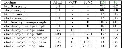
Table3shows the results for for multipliers mapped onto standard cells with three different libraries, including industrial libraries of 14 nm and 7 nm technology nodes. The results of verifying the same set of benchmarks using the open source tools available from [15][16], are included. The results of the first seven designs in the Table are generated using command-a in Table 2. For the last two circuits, mapped onto industrial libraries, we executed several iterations ofdch andstrash commands before ARTi to eliminate extra logic introduced for the purpose of meeting the timing constraints.
To apply ARTi to Booth-encoded multipliers, such as radix-4 Booth multiplier, the design needs to be first preprocessed by extracting the adder trees using the XOR-MAJ extraction approach, described in Section 3, using a command &atree. In addition, a semi-canonical spectral approach that represents the arithmetic functions in an algebraic spectrum form can be used to further improve the ARTi for Booth multipliers [22]. The examples of such circuits, verified with this method, are included in our repository4.
3http://fmv.jku.at/algeq/
Table 3: Verification time (sec) of synthesized, technology mapped multipliers using different libraries. #GT = Number of gate types used. FI≥5 = Number of gates with fanin≥5.
Designs ARTi #GT FI≥5 [15] [16]
btor64-resyn3 0.1 - - 711 4.2
abc64-resyn3 0.1 - - 801 4.0
btor128-resyn3 0.3 - - ES ES
abc128-resyn3 0.1 - - ES ES
btor64-resyn3-map-simple 0.3 7 0 1073 418 abc64-resyn3-map-simple 0.1 7 0 1071 415 abc64-resyn3-map-14nm 35 15 17 TO TO abc64-resyn3-map-7nm MO 24 9,791 TO TO abc128-resyn3-map-simple 1.8 7 0 ES ES abc128-resyn3-map-14nm 406 15 1,008 ES ES abc128-resyn3-map-7nm MO 23 26,600 ES ES
4.2
Complex Arithmetic Circuits
Table4shows the results of extracting word-level specifications from gate-level complex arith-metic circuits, constructed with multiplication and addition operations, and a three-operand multiplier. The multiplications in these datapaths are implemented using ABC-generated mul-tipliers. Our approach can efficiently identify the word-level operations in the gate-level dat-apaths. In contrast, the approach of [18] could not detect the presence of multiplication or addition in these circuits; and our approach is much faster than [20].
Table 4: Results of extracting word-level specification from complex arithmetic circuits. TO
= TIME OUT (3600 s). Error = Unable to determine type of arithmetic operations. TO*: finished in 23,760 s.
256-bit [18] [20] Ours
F=A×B+C Error TO* 1×mult;1×add 44.7 s F=A×(B+C) Error TO 2×mult 45.1 s F=A×B×C Error TO 1×mult3 68.5 s
4.3
Dividers (Divide by Constant)
This section presents the results for a special class of dividers, namely divide-by-constant cir-cuits. The input to the circuit are the dividendX and the divisor constantD; the outputs are the quotientQand the remainderR, concatenated to form an output word, Z= [R.Q]. In our experiment, the primary inputs and outputs aren-bit wide. Functional specification of such dividers can be expressed asX =Q·D+R, where the divisorD is a constant.
Restoring Divider: First, we consider an architecture based on a standardrestoring divider
[9], in which the divisorD has been hardwired to a particular constant. The restoring divider has been implemented and synthesized using ABC [1]. During synthesis, the constant bits of the dividerD have been propagated through the circuit and used to optimize the circuit.
Given a divider circuit to be verified, first step in the verification process is to create an output signature,Sigout =Q·D+R, determined by the number of output bits ofQ, Rand by
the value of the constant divisorD. In the case of the divide-by-3 circuit, withX, D, Q, Rall being three-bit words, the output signature is
or, alternatively, when expressed in terms of the output bitsZ
Sigout = 12Z2+ 6Z1+ 3Z0+ 4Z5+ 2Z4+Z3
In our experiment, the initial divider circuit and the output signature were obtainted by the program written in python as follows:
python verify_constant_divider_abc.py -f gen-div.blif -divisor 011 -divexp 1+0
Here, the gen-div.blif file is the generic divider to be converted to a divide-by-constant circuit; -f indicates the required output format type; -divisoris the value of the divisor in binary format; and -divexpis the value of exponent in the required sum form (for example, constant 3 = 011 = 21+ 20, is written as 1+0). This program produces a divide-by-3 circuitconst-div.blif and the output signature file,S.out= 3∗o0+4∗o1+5∗o2−1∗o0−2∗o1−3∗o2+0∗o3+1∗o4+2∗o5. The following ABC command is then used to computeSigin:
read const-div.blif; sweep; strash; dch; &get;
&polyn -v -w -S 3*o0+4*o1+5*o2-1*o0-2*o1-3*o2+0*o3+1*o4+2*o5;
with the output signature provided with a -S switch. The resulting input signature for this circuit obtained by ABC is x0+ 2x1+ 4x2 (internally encoded in the exponent form as 0∗
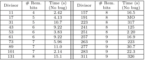
i0 + 1∗i1 + 2∗i2). This result matches the primary input, dividend X, which confirms that the circuit correctly implements the division. Table5shows the verification CPU runtimes for different divisors for a 16-bit dividendX.
Table 5: Results of verifying the divide-by-constant restoring divider circuit for a 16-bit dividendX. Time-out of 20 minutes, Memory-out 24GB.
Divisor # Rem. bits
Time (s)
(No bug) Divisor
# Rem. bits
Time (s) (No bug)
11 4 2.42 157 8 16.5
17 5 4.13 191 8 MO
31 5 10.7 223 8 317
43 6 9.22 241 8 125
53 6 3.83 251 8 2.20
61 6 9.22 257 9 16.9
73 7 5.96 263 9 223
89 7 11.0 277 9 30.7
101 7 2.14 283 9 22.3
131 8 15.1 311 9 326
Modular Divider: We also present an alternative, modular divider architecture, in which the divider is partitioned into a number of identical blocks, instantiated the required number of times, connected in series; each block has a fixed number of bits for the dividendXand quotient Q. A carry-inCinto each block comes from the remainderRof the previous block. The number of bits ofCandRis fixed and determined by the number of bits of the divisorD. The circuits were generated using an open-source hardware generator, FloPoCo [3], and synthesized using ABC tool [1] onto standard cell, gate-level circuits. For the reason of format incompatibility, these experiments applied the functional verification technique based on standard gate-level rewriting of [20], rather than AIG rewriting. The gate-level synthesized designs from ABC were converted into an algebraic equation format to perform block by block verification.
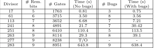
Table 6: Verification results of divide-by-constant divider circuits for aone-bit block archi-tectureand a 32-bit dividendX. Time-out of 20 minutes.
Divisor # Rem.
bits # Gates
Time (s)
(No bugs) # Bugs
Time (s) (With bugs)
17 5 1763 0.81 3 0.75
61 6 3715 3.50 8 3.56
113 7 3652 6.68 7 7.21
241 8 4891 21.7 7 30.42
251 8 6410 110.4 5 113.5
263 9 8114 29.3 8 39.1
277 9 8238 T/O -
-283 9 8951 643.8 9 638.4
The experiments include both correct (bug-free) and faulty circuits. The faults were em-ulated by randomly injecting multiple faults in the truth table into the valid portion of the LUT. Table 6 includes the verification time for the divide-by-constant, one-bit (of X) block architecture. The results are shown for a 32-bit dividend X, divisors D value up to 283, and a 9-bit remainder R. The non-monotonic behavior of the verification time as a function of the divisor size can be explained by examining the content (on-set) of the truth table for the corresponding division and its dependence on the value of the divisor.
4.4
Interactive Examples
The following example shows the script and the results of verifying, i.e., deriving the specifica-tion of a 64-bit multiplier, using the ABC system with &polyn command.
abc 01> gen -N 64 -m mult-abc-64.blif; strash; &get; &ps; &polyn -w > mult64.log
The results are shown below in two formats: (option 1) implicitly, by listing the number of coefficients appeared in the computed polynomial; and (option 2) explicitly, by listing all the monomials; only a small subset is listed here for brevity.
abc 01> gen -N 64 -m mult64-abc.blif;st;strash;ps
Hierarchy reader flattened 8256 instances of logic boxes and left 0 black boxes. Multi64 : i/o = 128/ 128 lat = 0 and = 32064 lev =501
abc 04> &get;&ps;
Multi64 : i/o = 128/ 128 and = 32064 lev = 501 (312.05) mem = 0.37 MB
Verbose option 1
abc 04> &polyn -w
Polynomial with 4096 monomials: | +2^0 * i0 * i64
| +2^1 * i0 * i65 +2^1 * i1 * i64 ...
Verbose option 2
abc 04> &polyn -v
Input signature with 4096 monomials: +2^0 appears 1 times
+2^1 appears 2 times +2^2 appears 3 times ...
The following log shows the usage of the tool by explicitly providing the output signatureSigout
in terms of the weights of the output bits, for a 2-bit unsigned integer multiplier. Sigout =
1z0+2z1+4z2+8z3is coded showing only exponents of the coefficients: 0*o0+1*o1+2*o2+3*o3,
with symbolok referring to the kth output bit with coefficient 2k.
Hierarchy reader flattened 10 instances of logic boxes and left 0 black boxes. HashC = 7. HashM = 25. Total = 40. Left = 4. Used = 4. Time = 0.00 sec Input signature with 4 monomials:
+2^0 appears 1 times +2^1 appears 2 times +2^2 appears 1 times Polynomial with 4 monomials: | +2^0 * i0 * i2
| +2^1 * i0 * i3 +2^1 * i1 * i2 | +2^2 * i1 * i3
The computed input signature is: Sigin = 1i0i2+ 2i0i3+ 2i1i2+ 4i1i3, which matches the
specification of the two-bit unsigned multiplier, (i0+ 2i1)(i2+ 2i3).
An example of the gate-level rewriting is demonstrated with an earlier (non-AIG based) version of our tool, petBoss [2]5. This tool takes an equation file (an example given in the
source directory) and produces the input signature polynomial. TheSigout must be appended
as the last line of the netlist equation file.
:~/abc/petBoss/petBoss-source: ./petBoss -b < ../mult4-syn.eqn
>>>>>>>>>>> a0*b0+2*a0*b1+2*a1*b0+4*a0*b2+...+32*a2*b3+32*a3*b2+64*a3*b3
5
Conclusions
The paper describes a practical tool for functional verification of integer arithmetic circuits. It uses algebraic representation of the circuit and performs an algebraic backward rewriting either structurally, on a gate-level netlist, or functionally, on its AIG representation. The alge-braic model explicitly considers finite bit-width words, and as such naturally handles modular, integer modulo 2n, signed and unsigned arithmetic circuits. Experimental results show the
ef-fectiveness of the tool in proving functional verification of add/subtract and fused add-muliply circuits, multipliers, including some Booth-encoded circuits, and a special case of dividers, namely divide-by-constant. Extensions to other arithmetic circuits, including restoring and non-restoring array dividers is currently under work.
References
[1] R. Brayton and A. Mishchenko. ABC: An Academic Industrial-Strength Verification Tool. In Proc. Intl. Conf. on Computer-Aided Verification, pages 24–40, 2010.
[2] M Ciesielski, C Yu, W Brown, D Liu, and Andr´e Rossi. Verification of Gate-level Arithmetic Circuits by Function Extraction. InDAC 2015, pages 1–6. ACM, 2015.
[3] Florent De Dinechin and Bogdan Pasca. Designing custom arithmetic data paths with flopoco. IEEE Design & Test of Computers, 28(4):18–27, 2011.
[4] W. Decker, G.-M. Greuel, G. Pfister, and H. Sch¨onemann. Singular3-1-6 A Computer Algebra System for Polynomial Computations. Technical report, 2012. http://www.singular.uni-kl.de. [5] Farimah Farahmandi and Bijan Alizadeh. Groebner basis based formal verification of large
arith-metic circuits using gaussian elimination and cone-based polynomial extraction. Microprocess. Microsyst., 39(2):83–96, March 2015.
[6] Farimah Farahmandi and Prabhat Mishra. Automated test generation for debugging multiple bugs in arithmetic circuits. IEEE Transactions on Computers, 2018.
[7] S. Ghandali, C. Yu, D. Liu, W. Brown, and M. Ciesielski. Logic debugging of arithmetic circuits. InISVLSI’15, pages 113–118, July 2015.
[8] Utkarsh Gupta, Irina Ilioaea, Vikas Rao, Arpitha Srinath, Priyank Kalla, and Florian Enescu. On the rectifiability of arithmetic circuits using craig interpolants in finite fields. Intl. Conf. on VLSI (VLSI-SOC’18).
[9] Israel Koren. Computer Arithmetic Algorithms. Universities Press, 2002.
[10] J. Lv, P. Kalla, and F. Enescu. Efficient Grobner Basis Reductions for Formal Verification of Galois Field Arithmatic Circuits. TCAD, 32(9):1409–1420, September 2013.
[11] A Mishchenko et al. Abc: A system for sequential synthesis and verification. URL http://www. eecs. berkeley. edu/˜ alanmi/abc, 2007.
[12] E. Pavlenko, M. Wedler, D. Stoffel, W. Kunz, A. Dreyer, F. Seelisch, and G.M. Greuel. Stable: A new qf-bv smt solver for hard verification problems combining boolean reasoning with computer algebra. InDATE, pages 155–160, 2011.
[13] T. Pruss, P. Kalla, and F. Enescu. Efficient symbolic computation for word-level abstraction from combinational circuits for verification over finite fields. IEEE Transactions on Computer-Aided Design of Integrated Circuits and Systems, 35(7):1206–1218, July 2016.
[14] Vikas Rao, Utkarsh Gupta, Irina Ilioaea, Arpitha Srinath, Priyank Kalla, and Florian Enescu. Post-Verification Debugging and Rectification of Finite Field Arithmetic Circuits using Computer Algebra Techniques. FMCAD’18.
[15] Daniela Ritirc, Armin Biere, and Manuel Kauers. Column-wise verification of multipliers using computer algebra. InFMCAD’17, 2017.
[16] Daniela Ritirc, Armin Biere, and Manuel Kauers. Improving and extending the algebraic approach for verifying gate-level multipliers. InDATE’18, 2018.
[17] Amr Sayed-Ahmed, Daniel Große, Ulrich K¨uhne, Mathias Soeken, and Rolf Drechsler. Formal verification of integer multipliers by combining grobner basis with logic reduction. InDATE’16, pages 1–6, 2016.
[18] Mathias Soeken, Baruch Sterin, Rolf Drechsler, and Robert Brayton. Simulation graphs for reverse engineering. InProceedings of the 15th Conference on Formal Methods in Computer-Aided Design, pages 152–159. FMCAD Inc, 2015.
[19] T. Su, A. Yasin, C. Yu, and M. Ciesielski. Computer algebraic approach to verification and debugging of galois field multipliers. In 2018 IEEE International Symposium on Circuits and Systems (ISCAS), pages 1–5, May 2018.
[20] Cunxi Yu, Walter Brown, Duo Liu, Andr´e Rossi, and Maciej J. Ciesielski. Formal verification of arithmetic circuits using function extraction.TCAD, 35(12):2131–2142, 2016.
[21] Cunxi Yu, Maciej J. Ciesielski, and Alan Mishchenko. Fast Algebraic Rewriting Based on And-Inverter Graphs.IEEE Trans. on CAD of Integrated Circuits and Systems, 37(9):1907–1911, 2018. [22] Cunxi Yu, Tiankai Su, Atif Yasin, and Maciej J. Ciesielski. Spectral approach to verifying