15 Iranian Journal of Chemical Engineering
Vol. 6, No. 4 (Autumn), 2009, IAChE
Experimental Study on the Effect of Heat Loads, Fill Ratio and
Extra Volume on Performance of a Partial-Vacuumed
Thermosyphon
H. Mirshahi, M. Rahimi
CFD Research Center, Chemical Engineering Department, Razi University, Kermanshah, Iran.
Abstract
This paper reports a study on the effect of the heat flux, cooling water flow rate, fill ratio and extra volume on the overall performance of a partially vacuumed thermosyphon. A rig was made from a 1 m copper tube with an inner and outer diameter of 17.5 and 19 mm. The heights of the evaporator, the adiabatic section and the condenser are 40, 20 and 40 cm, respectively. The temperatures at different places on the thermosyphon and on the inlet/outlet of the cooling water were measured. It was observed that change in heat flux, fill ratio and employing different extra volumes, has a significant effect on its performance. On the other hand, with changes in the cooling water flow rate the performance of the thermosyphon was altered regarding the trapped air movement. In order to illustrate the effect of the existence of air in deactivating the thermosyphon, the pipe was cooled down by disconnecting the evaporator power input. It was seen that the thermosyphon loses its performance as the trapped gas occupies the whole condenser. The whole study shows that due to the existence of the trapped air, the heat loads can have significant effects on the thermosyphon performance.
Keywords: Energy recovery, Thermosyphon, Heat transfer, Performance, Partial vacuum, Fill Ratio
Corresponding author: [email protected]
Introduction
Due to the human need for energy, a more efficient way of using it is a major challenge in the scientific community. The performance of heat transfer is one the most important parts of these types of investigation. The heat pipe is one piece of industrial equipment for transferring heat with reasonable efficiency. The advantage of using a heat pipe is its need for a small area and temperature difference.
heat pipes in which fluid circulation occurs inside due to gravity is called "Two phase closed thermosyphon" [2]. The first heat pipe which used the capillary of the fluid for its movement was fabricated by Gaugler (1994) [3]. Consequently, Grover et al. (1966) [4]
showed that the performance of the heat pipe for transferring heat can be more than metals
with high conductivity. This device was called "Heat Pipe" for the first time.
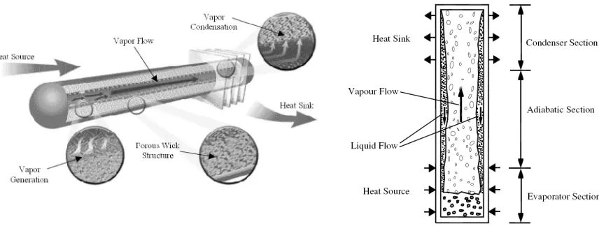
A heat pipe consists of an insulated pipe, a wick and working fluid as shown in Fig. 1a. The two phase closed thermosyphon is a type of heat pipe which has no wick for transferring the fluid, and the fluid moves inside the pipe due to differences in the gravity of the working fluid. Every heat pipe has three sections including: an evaporator, an adiabatic section and a condenser. In thermosyphons, the condenser is always placed above the evaporator, while in heat
pipes with a wick it can be placed below the evaporator [1].
Fig. 1b shows a two phase closed thermosyphon with its components. As the figure shows, the heat is input through the evaporator section where a liquid pool exists,
turning the working fluid into vapor. The vapor rises and passes through the adiabatic
section to the condenser section. In the condenser section, the vapor condenses and gives up its latent heat. Then, the effect of gravity on fluid returns the condensate back to the evaporator section. Due to their high efficiency, reliability and cost effectiveness, thermosyphons have been used in many different applications. These applications include preservation of permafrost, de-icing of roadways, turbine blade cooling, heat exchangers [1], humidity control [5], food industry [6], gas industry [7], solar systems [8, 9] and reactors [10].
Figure 1. Schematic views of heat pipe and thermosyphon
Iranian Journal of Chemical Engineering, Vol. 6, No. 4 17 There is a type of heat pipe which is called
Gas-Loaded Heat Pipe. This type of heat pipe contains non-condensable gas (NCG) such as air. They are employed for systems need the evaporator section that works in isothermal condition. However, this condition in other
systems may be established due to in- complete drainage of air from the system.
The NCG fills a part of the condenser and deactivates that part. Therefore, the system works at partially vacuum condition. Fig. 2 illustrates the role of the existence of the non-condensable gas on the performance of a heat pipe [1, 13].
Numerous research works were carried out in
order to study the thermosyphon efficiency and the ways it can be used for enhancing its performance. An experimental modeling of condensation in a cylindrical two phase closed thermosyphon containing non-condensable gas was carried out by Zhou and
Collins [14]. They claimed that they were able to determine the spatial distribution of
condensing heat flux from accurate measurements of the thickness of the condensed liquid film. They also reported that their experiments were done in different situations of high, low and very low power levels.
A comprehensive model was developed by Jiao et al. [15] to investigate the effect of fill ratio on the steady-state heat transfer performance of a vertical thermosyphon. Three types of flow pattern and two types of transition, according to the distribution of
liquid film and liquid pool were considered in their model, while other models generally
only focused on one or two types. The total heat transfer rate of the liquid pool, including those of natural convection and nucleate boiling, was calculated by combination of their effective areas and heat transfer coefficients. New correlations of the effective area were proposed based on the experimental results. The effects of heat input, operating pressure and geometries of the thermosyphon were also discussed by the authors.
A two-phase gravity assisted thermosyphon was designed, fabricated and tested with three nanofluids based on water (with 1% by weight of Al2O3, CuO, and laponite clay) by Khandekar et al. [16]. They obtained thermal performance using pure water as the working fluid. It was observed that thermal performance deteriorates when nanofluids are used as working fluids. Maximum deterioration was observed with laponite while minimum deterioration was for aluminum oxide particles based nanofluids. In addition, they observed that the wettability of all nanofluids on copper substrate, having the same average roughness as that of the thermosyphon container pipe, is better than that of pure water. A scaling analysis was presented which showed that the increase in wettability and entrapment of nanoparticles in the grooves of the surface roughness
caused a decrease in the evaporator side Peclet number that finally lead to poor thermal performance.
Nuntaphan et al. [17] studied the critical heat flux (CHF) due to the flooding limit of the thermosyphon heat pipe using triethylene
glycol (TEG)–water mixture. From the experiment they found that, use of TEG–
water mixture can extend the heat transport limitation compared with pure water and higher heat transfer can be obtained in comparison with pure TEG at high temperature applications. In addition, it was found that ESDU equation is appropriate to predict the CHF of the thermosyphon in the case of TEG–water mixture. For thermosyphon air preheater at high temperature applications, it was found that with a selected mixture content of TEG– water in each row of the thermosyphon the performance of the system could be increased approximately 30–80% compared with pure TEG for parallel flow and 60–115% for counter flow configurations. They showed that the performances increase approximately 80–160% for parallel flow and 140–220% for counter flow compared with those of pure dowtherm, which is the common working fluid at high temperature applications.
Iranian Journal of Chemical Engineering, Vol. 6, No. 4 19 vertical thermosyphons was built. The
experimental measurements show that the thermosyphons were able to provide a uniform temperature distribution inside the cooking chamber without the appearance of any overheated spot. In addition to the
experimental setup, a theoretical lumped model was used to predict the air temperature
variation and the relative importance of the convective and radiative heat transfer modes inside the cooking chamber. The finite difference technique was applied for the computation of the non-linear differential system. They reported a good agreement between the model and the experimental data. In addition, they found that the radiation was the major heat transfer mechanism inside the cooking chamber.
The experimental analysis of the thermal behavior of two-phase closed thermosyphons with an unusual geometry characterized by a semicircular condenser and a straight evaporator was investigated by Abreu and Colle [9]. All the tests were done in an experimental indoor setup that uses electrical skin heaters to simulate the solar radiation. Different evaporator length, fill ratios of working fluid, cooling temperatures and slopes of the evaporator were tested for different heat fluxes. The analysis of the transient results and the steady state performance were used in order to provide information for the design of a compact solar domestic hot-water system.
More recently, the effect of the inclination angle on the thermal performance of a two-phase closed thermosyphon with different filling ratios was investigated experimentally by Noei et al. [19]. A series of experiments
were carried out for inclination angle range of 5◦
–90◦ and filling ratios of 15%, 22%, and 30%. Their results showed that their two-phase closed thermosyphon had the highest thermal performance in theinclination angle
range of 15–60. The authors reported a good agreement was observed between the experimental results of that study and those available in the literature. The interesting phenomenon of geyser boiling occurred in our experiments for filling ratiosequal to or greater than 30%.
In the present research, the effect of the heat flux and the cooling water flow rate of the condenseron the overall performance of a partially vacuumed thermosyphon were studied. In addition, the effect of fill ratio and implement extra volumes on the ther-mosyphon tube were investigated. As far as the evacuation of non-condensation gas from a thermosyphon having a significant effect on its performance, the obtained results can be quite attractive.
Experiments
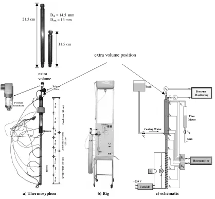
Fig. 3 shows the real and schematic view of the experimental rig as well as the thermosyphon with its accessories. The thermosyphon was made from a 1 m copper tube with inner and outer diameters of 17.5
and 19 mm respectively. A closed copper tube with a length of 40 cm and a diameter of
streams of the condenser were measured. In addition, the pressure was measured at the top of the thermosyphon as shown in the figure. The energy was transferred to the evaporator section by an electrical heater with a predefined power input. The input
energy was 2 KW, which was transferred via an electrical energy regulator.
Water was used as working fluid and fill ratios of 0.3, 0.5 and 0.8 were used in different experiments. The vacuum was established by simply heating the tube and purging the air by opening the release valve.
The experiments were carried out using three heat rates of 350, 500 and 700 W which transferred heat to the evaporation section. In experiments the cooling water rates of 7 and 14 cm3/s were used in the condenser. The inlet temperature of cooling water in all
experiments was constant at 20°C. In
addition, 16 and 32 cm3 extra volumes made
from the same tube were welded at the end of the thermosyphon condenser for studying the effect of trapped air on the thermosyphon performance.
Figure 3. The experimental setup
b) Rig c) schematic
a) Thermosyphon
extra volume position
21.5 cm
11.5 cm Din = 14.5 mm Dout = 16 mm
Iranian Journal of Chemical Engineering, Vol. 6, No. 4 21
Heat transfer limitations
Although heat pipes are very efficient heat transfer devices, there are various parameters that put limitations and constraints on the steady and transient operation of these pipes. These limitations determine the maximum
heat transfer rate, which must be examined for each working fluid. The type of limitation
that restricts the operation of the heat pipe is determined by the one that has the lowest value of heat transfer rate at a specific heat pipe working temperature. Physical phenomena that might limit heat transport in two-phase closed thermosyphons are due to flooding, dry-out, and boiling [19].
In general, liquid entrainment or flooding is due to the interaction between the countercurrent liquid and vapor flows occurring at the liquid-vapor interface in the thermosyphon [1]. This limit is one of the most important and common limitations found in thermosyphons [16]. The flooding limit was evaluated based on a correlation proposed by Faghri [1]:
l 14
24 1 v 4 1 v l cross fg 90 ,
c Kh A g ( )
Q
(1) 4 1 2 14 . 0 v
l tanh (Bo)
K (2)
g( l v)
0.5 dBo (3)
The boiling limitation is observed in thermosyphons having a large liquid fill ratio and high radial heat fluxes in the evaporator section. Under this limitation, at the critical heat flux, vapor bubbles coalesce near the
pipe wall prohibiting the contact of working liquid to wall surface, resulting in the rapid increase in evaporator wall temperature. For boiling limitation, we make use of the correlation suggested by khandekar [16]:
l v
145 . 0 v fg rad 90 , c BL ) ( g h A Q Ku (4)
0.13
v l e
BL 0.161 exp( d L )( )
Ku (5)
Dry-out limitation occuring for the fill charge ratio is relatively small. The condensate falls
down along the wall and reaches the evaporator. The condensate starts evaporating and boiling by the input power and as it
comes closer and closer to the bottom, the thickness of the condensate film is thinner. It eventually dries out, so the wall temperature rises from the bottom of the evaporator at the limitation. Dry-out limitation is determined by the following correlation [1, 20]:
3 3 3 2 4 2 2 4 1 2 90 1 4 3 5 4 3 ) ( ) ( ) V V )( V V ( ) L L ( ) D D ( ) L L ( D V ) ( g L ) D D ( g A ) ( g h Q l v l v e l t e e ae c e ac c c t v l v e l e c l cross v v l fg v , c (6)
that the thermosyphon was operated in the right situation.
Table 1. Heat transfer limits
F.R.
Limitation 30% 50% 80%
Flooding (W) 2500 2500 2500
Boiling (W) 2000 2000 2000
Dry out (W) 1300 6200 25700
Result and Discussion
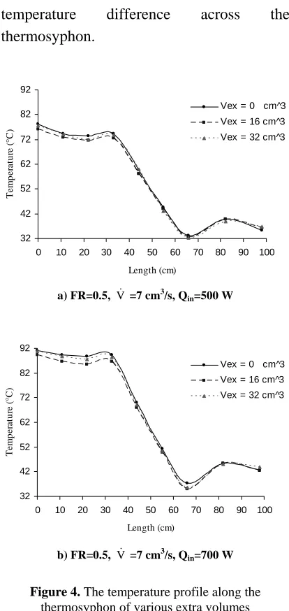
Fig. 4 shows the temperature profile along the thermosyphon at different setups using three different extra volumes. The results show that the overall temperature difference was affected by the values of extra volume. In addition, the results show that increasing the extra volume can increase or decrease the overall temperature difference. The minimum overall temperature difference was found for 16 cm3 extra volume. This indicates that increasing this volume has an optimum value. The positive effect on reducing the overall temperature difference can be explained by the trapped air in the employed extra volume. However, due to increasing the volume beyond the optimum volume, a part of the working fluid goes above the condenser. This caused a reduction of the working fluid volume in the liquid state inside the evaporator. On the other hand, there is an optimum condition for fill ratio as is shown in Fig. 5. The figure illustrates how the amount of fill ratio can reduce the temperature difference across the thermosyphon. The results show that the optimum condition occurred at the full ratio of 0.5. In addition, the illustrated graphs in Fig. 4 show that increasing the heat input beyond the optimum values caused a higher
temperature difference across the thermosyphon.
32 42 52 62 72 82 92
0 10 20 30 40 50 60 70 80 90 100
Length (cm)
T
e
m
p
e
rat
u
re (
°C)
Vex = 0 cm^3 Vex = 16 cm^3 Vex = 32 cm^3
a) FR=0.5, V =7 cm3/s, Qin=500 W
32 42 52 62 72 82 92
0 10 20 30 40 50 60 70 80 90 100
Length (cm)
T
e
m
p
e
rat
u
re (
°C
)
Vex = 0 cm^3 Vex = 16 cm^3 Vex = 32 cm^3
b) FR=0.5, V =7 cm3/s, Q
in=700 W
Figure 4. The temperature profile along the thermosyphon of various extra volumes
In order to illustrate the effect of the heat load, fill ratio and extra volume on thermosyphon performance, a relation called thermosyphon performance has been proposed as follows:
) T T ( c V
Qout =ρw p h − c (7)
100 * Q Q
in out =
Iranian Journal of Chemical Engineering, Vol. 6, No. 4 23
a) Vex=16 cm3, Qin=500 W, V =7 cm3/s
28 38 48 58 68 78 88
0 10 20 30 40 50 60 70 80 90 100
Length (cm)
T
e
m
p
e
ra
tu
re
(
°
C
)
FR = 0.3 FR = 0.5 FR = 0.8
b) Vex=16 cm3, Qin=500 W, V =14 cm3/s
Figure 5. The temperature profile along the thermosyphon of various fill ratios
Qin is the input heat to the evaporator and
Qout is the heat absorbed by the condenser. In
addition, Th and Tc are the input and output
temperatures of the cooling water passing through the condenser.
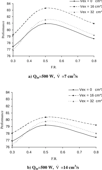
Fig. 6 shows the effect of fill ratio on the thermosyphon performance as it was employed at two cooling water flow rates. The figure indicates that adding more extra volume on the thermosyphon can have a significant effect on the thermosyphon
performance. As can be seen in the figure, the maximum performance occurred at the
fill ratio of 0.5 and for the extra volume of 16 cm3. The figure also illustrates that at fill ratio lower than 0.4, using the extra volume of 32 cm3 caused a lower performance compared with a plain thermosyphon. This can be explained by the lower established
liquid to gas ratio inside the tube. In addition, as can be seen in the figure, the increase in
the cooling water flow rate caused a reduction in the thermosyphon performance.
76 77 78 79 80 81 82 83 84
0.3 0.4 0.5 0.6 0.7 0.8
F.R.
P
e
rf
o
rm
a
n
c
e
Vex = 0 cm^3 Vex = 16 cm^3 Vex = 32 cm^3
a) Qin=500 W, V =7 cm3/s
76 77 78 79 80 81 82 83 84
0.3 0.4 0.5 0.6 0.7 0.8
F.R.
P
e
rf
o
rm
a
n
c
e
Vex = 0 cm^3 Vex = 16 cm^3 Vex = 32 cm^3
b) Qin=500 W, V =14 cm3/s
Figure 6. The thermosyphon performance of various fill ratios and extra volume
The thermosyphon performances at various fill ratios for the three studied heat loads are presented in Fig 7. The results confirm that the optimum fill ratio was 0.5 for all setups.
28 38 48 58 68 78 88
0 10 20 30 40 50 60 70 80 90 100
Length (cm)
T
e
m
p
e
ra
tu
re
(
°
C
)
In addition, the results show that increasing the heat load higher than the optimum condition can reduce the thermosyphon performance. It can be argued that in a very high circulate regime caused by high energy input, the resistance of the produced film
could have a negative effect on transforming heat from the evaporator to the working fluid.
This is more obvious as the fill ratio increase to 0.8, in which the thermosyphon with a heat input of 700 W works at the same performance of 350 W. In addition, similar to the result presented in Fig. 6, the increase in the cooling water flow rate caused a reduction in the thermosyphon performance.
73 74 75 76 77 78 79 80 81
0.3 0.4 0.5 0.6 0.7 0.8
F.R.
P
e
rf
o
rm
a
n
c
e
700 500 350
a) Vex=0 cm3, V =7 cm3/s
73 74 75 76 77 78 79 80 81
0.3 0.4 0.5 0.6 0.7 0.8
F.R.
P
e
rf
o
rm
a
n
c
e
700 W 500 W 350 W
b) Vex=0 cm3, V =14 cm3/s
Figure 7. The thermosyphon performance of various fill ratio and heat flux
In order to show how the expansion of air can decrease the condenser performance, an experiment was carried out by cutting the power input to the evaporator. Fig. 8 shows the recorded temperatures along the tube as well as the pressure. The positions of the
measuring points have been shown in Fig. 3. The figure shows that during the first 10
seconds there is a sharp decrease in temperature which corresponds to the high performance of the thermosyphon in transferring heat. However, after this period the thermosyphon did not work properly due to expansion of the air and deactivation of the condenser. At this stage the thermosyphon just worked as a simple tube.
Figure 8. The temperature and pressure of the thermosyphon after the heat input disconnection. The whole results show that the existence of
non-condensable gas inside a thermosyphon has a significant effect on the thermosyphon performance. The operational condition can
20 30 40 50 60 70 80 90
0 10 20 30 40 50 60
Time (s)
T
e
m
p
e
ra
tu
re
(
°
c
)
T1 T3 T6 T9 240
270 300 330 360 390 420 450 480
P
re
ss
u
re
(
m
B
ar
)
Iranian Journal of Chemical Engineering, Vol. 6, No. 4 25 change the extent of the effect of this
unfavorable effect on the system. However, using an optimum extra volume, working as a gas trap can improve the performance of a thermosyphon.
Conclusion
The trapped non-condensable gas in partially vacuumed thermosyphon has a significant effect on its performance.
Due to the existence of the trapped gas, increasing the heat load to the evaporator has an optimum point in improving the performance of the thermosyphon.
In partially vacuumed thermosyphon increase of cooling water flow rate decreases the performance of the thermosyphon.
In order to access the maximum performance of a thermosyphon when
employing it for transferring heat at lower temperature, more vacuum should be established inside it.
By using an optimum extra volume in a partially-vacuumed thermosyphon, it is more convenient to increase its performance
Acknowledgment
The authors wish to express their thanks to
the Kermanshah Branch of the Iranian National Gas Company for supporting this work.
Nomenclature
Across cross-sectional area of pipe, m2 Arad lateral surface of evaporator, m2
Bo Bond number
cp specific heat of water, J/kg.°C
d internal diameter of thermosyphon, m
Dc condenser diameter, m De evaporator diameter, m F.R. fill ratio of evaporator
g acceleration due to gravity, m/s2
hfg latent heat of vaporization, J/kg K modified Kutateladze number
KuBL Kutateladze number
Lac length of adiabatic section with diameter Dc, m
Lae length of adiabatic section with diameter De, m
Lc condenser length, m Le evaporator length, m Lt total length of pipe, m
Qc,90 heat transfer rate limits at vertical
thermosyphon, W
Qin input heat into the evaporator section, W
Qout transmitted heat from the
condenser, W
Tc inlet water temperature of
condenser, °C
Th outlet water temperature of condenser, °C
Ve evaporator volume, m3 Vex extra volume,cm3
Vl liquid volume, m3
Vt internal volume of pipe, m3
V
cooling water flow rate, cm3/s
Greek Symbols
ç thermosyphon performance
ìl dynamic viscosity of liquid, kg/m.s
ñl density of liquid, kg/m3
ñv density of vapor, kg/m3
ñw density of water, kg/m3
References
[1] Faghri, A., Heat pipe science and tech-nology, Taylor & Francis, Washington DC, USA, p. 341 (1995).
[2] Peterson, G.P., An introduction to heat pipes, modeling, testing and applications, John Wiley & Sons Inc., New York, USA, p.1 (1994).
[3] Gauglar, R.S., “Heat transfer device”, US
patent 2350348, 1942.
[4] Grover, G.M., “Evaporation–condensation heat transfer device”, US patent 3229759,
applied 2 December 1963.
[5] Wu, X.P., Johnson, P., and Akbarzadeh, A., "Application of heat pipe heat exchangers to humidity control in air-conditioning systems", Applied Thermal Engineering, 17 (6), 561, (1997).
[6] Dussadee, N., Punsaensri, T., Kiatsiriroat, T., "Temperature control of paddy bulk storage with aeration–thermosyphon heat pipe", Energy Conversion and Management, 48, 138 2007.
[7] Angelo, W., Mantelli, M.H., Milanez, F.H., "Design of a heater for natural gas stations assisted by two phase loop thermosyphon", 14th International Heat Pipe Conference (14th IHPC), Brazil, Florianópolis 2007. [8] Kalogirou, S.A., "Solar thermal collectors
and applications", Progress in Energy and Combustion Science, 30, 231 2004. [9] Abreu, S. L., and Colle, S., "An experimental
study of two-phase closed thermosyphons for compact solar domestic hot-water systems", Solar Energy, 76, 141, (2004). [10] Nayak, A.K., Lathouwers, D., van der
Hagen, T.H.J.J., Schrauwen, F., Molenaar, P., and Rogers,A.,"A Numerical study of boiling flow instability of a reactor thermosyphon system", Applied Thermal Engineering, 26, 644, (2006).
[11] Gernert, N., "Heat pipes drive power semiconductor temperatures down", PCIM Power Electronics Systems Magazine, (2000).
[12] Srihajong, N., Ruamrungsri, S., Terdtoon, P., Kamonpet, P., Ohyama, T., "Heat pipe as a cooling mechanism in an aeroponic system", Applied Thermal Engineering, 26, 267 (2006).
[13] Dunn, P., Reay, D.A., Heat Pipes, Pergamon Press, Third edition, New York, USA, p. 229 (1982).
[14] Zhou, X., Collins, "Condensation in a gas-loaded thermosyphon", Int J. Heat Mass Transfer, 38(9), 1602 (1995).
[15] Jiao, B., Qiu, L.M., Zhang, X.B., Zhang, Y., "Investigation on the effect of filling ratio on the steady-state heat transfer performance of a vertical two-phase closed thermosyphon", Applied Thermal Engineering, 28, 1417 2008.
[16] Khandekar, S., Joshi, Y. M., and Mehta B., "Thermal performance of closed two-phase thermosyphon using nanofluids", International Journal of Thermal Sciences,
47(6), 659, (2008).
[17] Nuntaphan, A., Tiansuwan, J., and Kiatsiriroat, T., "Enhancement of heat transport in thermosyphon air preheater at high temperature with binary working fluid: A case study of TEG–water", Applied Thermal Engineering, 22, 251 (2002).
[18] Silva, A.K., and Mantelli, M.B.H. ,"Thermal applicability of two-phase thermosyphons in cooking chambers-experimental and theoretical analysis", Applied Thermal Engineering, 24, 717, (2004).
[19] Noie, S.H., Sarmasti Emami, M.R., Khoshnoodi, M. "Effect of inclination angle and filling ratio on thermal performance of a two-phase closed thermosyphon under normal operating conditions", Heat Transfer Engineering,
28(4), 365, (2007).
[20] Park, Y. J., Kang, H.K. and Kim, C. J.,
“Heat transfer characteristics of a TPCT to
the fill charge ratio”, Int. Journal of Heat
![Figure 2. Gas Loaded Heat Pipe [13]](https://thumb-us.123doks.com/thumbv2/123dok_us/8888323.1823717/3.612.149.492.347.641/figure-gas-loaded-heat-pipe.webp)